
wear plate mud pump free sample

A wide variety of wear plate for mud pump options are available to you, such as 1 year, not available.You can also choose from new, wear plate for mud pump,As well as from energy & mining, construction works , and machinery repair shops. and whether wear plate for mud pump is 1.5 years, 6 months, or unavailable.
A wide variety of mud pump wear plate options are available to you, such as 1 year, not available.You can also choose from new, mud pump wear plate,As well as from energy & mining, construction works , and machinery repair shops. and whether mud pump wear plate is 1.5 years, 6 months, or unavailable.
The 2,200-hp mud pump for offshore applications is a single-acting reciprocating triplex mud pump designed for high fluid flow rates, even at low operating speeds, and with a long stroke design. These features reduce the number of load reversals in critical components and increase the life of fluid end parts.
The pump’s critical components are strategically placed to make maintenance and inspection far easier and safer. The two-piece, quick-release piston rod lets you remove the piston without disturbing the liner, minimizing downtime when you’re replacing fluid parts.

Mud-Pump Gear Sets . . . . . . . . . . . . . . . . . . . . . . . . . . . . . . . . . . . . . . . . . . . . . . . . . . . . . . . . . . . . . . . . . 13

If you run a mud rig, you have probably figured out that the mud pump is the heart of the rig. Without it, drilling stops. Keeping your pump in good shape is key to productivity. There are some tricks I have learned over the years to keeping a pump running well.
First, you need a baseline to know how well your pump is doing. When it’s freshly rebuilt, it will be at the top efficiency. An easy way to establish this efficiency is to pump through an orifice at a known rate with a known fluid. When I rig up, I hook my water truck to my pump and pump through my mixing hopper at idle. My hopper has a ½-inch nozzle in it, so at idle I see about 80 psi on the pump when it’s fresh. Since I’m pumping clear water at a known rate, I do this on every job.
As time goes on and I drill more hole, and the pump wears, I start seeing a decrease in my initial pressure — 75, then 70, then 65, etc. This tells me I better order parts. Funny thing is, I don’t usually notice it when drilling. After all, I am running it a lot faster, and it’s hard to tell the difference in a few gallons a minute until it really goes south. This method has saved me quite a bit on parts over the years. When the swabs wear they start to leak. This bypass pushes mud around the swab, against the liners, greatly accelerating wear. By changing the swab at the first sign of bypass, I am able to get at least three sets of swabs before I have to change liners. This saves money.
Before I figured this out, I would sometimes have to run swabs to complete failure. (I was just a hand then, so it wasn’t my rig.) When I tore the pump down to put in swabs, lo-and-behold, the liners were cut so badly that they had to be changed too. That is false economy. Clean mud helps too. A desander will pay for itself in pump parts quicker than you think, and make a better hole to boot. Pump rods and packing last longer if they are washed and lubricated. In the oilfield, we use a petroleum-based lube, but that it not a good idea in the water well business. I generally use water and dish soap. Sometimes it tends to foam too much, so I add a few tablets of an over the counter, anti-gas product, like Di-Gel or Gas-Ex, to cut the foaming.
Maintenance on the gear end of your pump is important, too. Maintenance is WAY cheaper than repair. The first, and most important, thing is clean oil. On a duplex pump, there is a packing gland called an oil-stop on the gear end of the rod. This is often overlooked because the pump pumps just as well with a bad oil-stop. But as soon as the fluid end packing starts leaking, it pumps mud and abrasive sand into the gear end. This is a recipe for disaster. Eventually, all gear ends start knocking. The driller should notice this, and start planning. A lot of times, a driller will change the oil and go to a higher viscosity oil, thinking this will help cushion the knock. Wrong. Most smaller duplex pumps are splash lubricated. Thicker oil does not splash as well, and actually starves the bearings of lubrication and accelerates wear. I use 85W90 in my pumps. A thicker 90W140 weight wears them out a lot quicker. You can improve the “climbing” ability of the oil with an additive, like Lucas, if you want. That seems to help.
Outside the pump, but still an important part of the system, is the pop-off, or pressure relief valve. When you plug the bit, or your brother-in-law closes the discharge valve on a running pump, something has to give. Without a good, tested pop-off, the part that fails will be hard to fix, expensive and probably hurt somebody. Pop-off valve are easily overlooked. If you pump cement through your rig pump, it should be a standard part of the cleanup procedure. Remove the shear pin and wash through the valve. In the old days, these valves were made to use a common nail as the shear pin, but now nails come in so many grades that they are no longer a reliable tool. Rated shear pins are available for this. In no case should you ever run an Allen wrench! They are hardened steel and will hurt somebody or destroy your pump.
One last thing that helps pump maintenance is a good pulsation dampener. It should be close to the pump discharge, properly sized and drained after every job. Bet you never thought of that one. If your pump discharge goes straight to the standpipe, when you finish the job your standpipe is still full of fluid. Eventually the pulsation dampener will water-log and become useless. This is hard on the gear end of the pump. Open a valve that drains it at the end of every job. It’ll make your pump run smoother and longer.

The invention relates to an assembly for quickly securing and releasing a component to a pump housing and more particularly to a retainer assembly for releasably mounting a piston liner within a hydraulic cylinder on the module of a pump.
Heavy duty large horsepower pumps are used to pump fluids or slurries with entrained solids. In the oil industry, for example, slush or mud pumps are used to pump viscous fluids, such as drilling muds, cement, or other well fluids. Although mud pumps may be either centrifugal or reciprocating type pumps, typically mud pumps are reciprocating pumps using one or more pistons and hydraulic cylinders with liners to generate the high pressures required to pump these viscous fluids in and out of the well.
Mud pumps include a fluid end and a power end. In the fluid end of one type of a triplex mud pump, for example, there are three sets of suction modules and discharge modules in fluid communication. A suction manifold is connected to the fluid inlets of the suction modules for receiving fluids and passing those fluids to each of the suction modules. A discharge manifold is connected to the fluid outlets of the discharge modules for discharging the pumped fluids. Each module encloses a set of flow passages with check valves for controlling the direction of flow of the fluids. A check valve is disposed at the suction module fluid inlet to only allow fluids to enter the suction module inlet end of the module and another check valve is disposed at the discharge module fluid outlet to only allow fluids to exit the the discharge module for flow into the discharge manifold.
Each discharge module includes a liner retainer flange attached to the discharge module. The liner retainer flange attaches to a replaceable liner within which a pump piston reciprocates. The piston is a generally cylindrical steel member having a polymer, such as polyurethane, bonded to its outer diameter for sealingly engaging the inner cylindrical wall of the liner to ensure a fluid tight seal required for drawing the low pressure fluids through the suction manifold and module flow passages. The seal integrity must be maintained to withstand the high discharge pressure on the discharge stroke. The power end contains the gears that reciprocate the pump piston within the liner for pumping the fluid through the module passages in the fluid end and thence out the discharge valve.
In operation, on the suction stroke, the pump piston draws fluids through the suction manifold and suction valve as the piston strokes within the liner. On the discharge stroke, the check valve in the discharge module opens simultaneously as the suction valve closes preventing suction back flow into the suction module. Fluid in the liner is compressed and pressure is built up until the pressure overcomes well bore pressure so as to pump the mud into the well. The piston then reverses for another suction stroke whereby the check valve in the suction module opens and the discharge valve closes simultaneously, the piston now making a suction stroke.
As the piston reciprocates within the liner, friction wears the liner. Further, the fluid passing through the fluid end includes particulates and other solids which wear away and destroy the liner and piston. When the liner and piston degrade, the fluid seal is lost and the pump becomes much less efficient. Also, the reciprocation of the piston in the liner causes pulsations that over time cause the liner to become loose within the containment of the liner retainer flange thus resulting in a degradation of the seal at the face of the liner and the seal at the face of the liner wear plate. Therefore, it is important to be able to replace the liner as a part of routine maintenance (or when emergencies occur from seal failure while drilling) to ensure that the pump operates efficiently and can control well pressure. It is also important to have a means for fastening the liner to the liner retainer flange so as to ensure that the liner remains firmly secured despite extended reciprocation of the piston assembly within the liner.
Typically each liner retainer flange, and the cradle of the pump power end are all secured to the fluid end module by studs and threaded connections. Because of the environment in which the mud pump operates and the corrosive nature of the fluids being pumped, the studs and threaded connections, such as nuts, become corroded and are difficult to unthread for the replacement of the liner. Often, the threaded connections have been over tightened, making it even more difficult to unthread. Where the liner is retained by an end cap, a steel bar is inserted into a guide hole in the side of the end cap and then the cap is unscrewed using a significant amount of torque. This end cap is very heavy as it must have sufficient strength to keep the liner from moving, even with pressures up to 7500 psi. Where a nut or end cap resists unscrewing, a sledge hammer is used to hammer on a socket wrench or a special hammer wrench is used to loosen the nut or cap. Such activity is obviously dangerous. In some regions of the world local laws prohibit the use of sledge hammers for personnel safety reasons or to avoid the risk of an explosion due to sparks.
Prior art liner retention systems include spring mechanisms around each stud with an end flange for securing the liner against a fluid end module. Hydraulic pressure is applied to the spring mechanism of each stud by a small hydraulic pump to remove the clamping force of the spring mechanism. The release of the clamping force allows the removal of the clamping flange of the liner retention system. Individually actuated spring loaded studs cause an uneven pressure to be applied to the clamping flange. Further, the clamping force is limited because of the limited space available to hold numerous springs.
The liner retainer assembly of the present invention includes a liner retainer flange that is mounted on the discharge module of the fluid end of a pump. A pressure actuated hydraulic clamping piston with related actuated, conical dished washers and necessary static and sliding seals is disposed within the retainer flange . The hydraulic pressure actuated clamping piston is configured to receive and hold the liner. The hydraulic clamping piston and an end cap maintain the liner in contact with the module during actuation. The hydraulic clamping cylinder includes a counterbore which is divided by the hydraulic piston into a fluid cavity and a spring cavity. The spring cavity houses a plurality of springs which bias the hydraulic piston, end cap, and liner towards the module, thus providing a strong clamping securing force when the hydraulic pressure is released. The fluid cavity communicates with a supply of hydraulic fluid for biasing the hydraulic piston away from the module to activate the springs. By pressurizing the fluid cavity, the springs are compressed so as to disengage the liner retaining end cap from the liner and allow the unthreading of the liner end cap to then remove the liner.
The liner retainer assembly permits preloading or prestressing of the liner against the module of the fluid end of the pump so that the liner will not loosen upon the reciprocation of the pump piston within the liner. Further, the liner may be easily secured and unsecured from the module without the necessity of a sledge hammer or other methods for applying excessive amounts of torque to a securing fitting. The assembly of the present invention permits the easy and quick replacement of the liner as necessary.
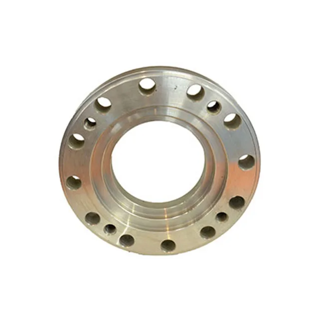
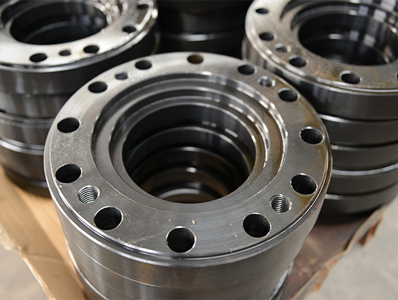
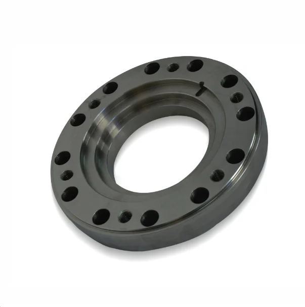
Referring first to FIGS. 1 and 2, there is shown a fluid end module 10 and a cradle 28 of the pump power end. The pump is of the type used to pump fluids, such as drilling muds, cement or the like. Pumps of this type are well known. A wear plate 14 defines a bore 16 which leads into liner 20. The module 10 is used for the transfer of fluid from the suction manifold and suction module (not shown) to the discharge manifold (not shown) and discharge module.
An exemplary liner retaining flange assembly 18 of the present invention is used to secure liner 20 within a hydraulic cylinder 30 mounted on module 10 and liner retainer flange 22. Those of skill in the art will understand that a pump piston (not shown) attached to the power end of the pump is reciprocated within the liner 20 to effect the desired pumping action to flow fluid through the fluid end module 10 of the pump. Hydraulic cylinder 30 provides an open end into which the liner 20 is inserted. Module 10 also provides a counterbore 12 for the adjacent wear plate 14 against which it is desired to retain the liner 20 during operation of the pump piston. It can be appreciated that the purpose of wear plate 14 is to avoid the end of liner 20 wearing module 10 due to the reciprocation of the piston within liner 20. However, wear plate 14 may cause wear to the module 10 if the liner 20 is not securely affixed. Wear plate 14 may be replaced should that wear become excessive. It is noted that the end of the liner 20 adjacent the wear plate 14 includes an internal annular groove 59 with seal member 61 for sealingly engaging the wear plate 14 and the other open end 15 of liner 20 includes an external annular load-bearing shoulder 60 which retains end cap 64 (FIG. 2).
The hydraulic cylinder 30 includes a threaded, reduced diameter portion 24 and an enlarged diameter portion 32. Reduced diameter portion 24 is secured in a threaded or splined relation at 23 to liner retainer flange 22 that is located in an abutting relation to the module 10. Bolted studs 26 secure the cradle 28 of the pump power end, the liner retaining flange 22 and hydraulic cylinder 30 to module 10.
When these components are assembled, the annular flange 44 of piston 42 forms hydraulic cavity 58 and outer spring cavity 35. The hydraulic fluid port and fitting 38 communicates with hydraulic cavity 58 for applying hydraulic pressure to flange 44. The spring cavity 35 houses a plurality of axially compressible Belleville springs or washers 56. Retainer ring 48 has external threads 50 which threadingly mate in a complimentary fashion with the internal threads 34 of enlarged diameter portion 32. The washers 56 bear against the retainer ring 48 and annular flange 44. Enough springs are used so as to insure sufficient force is generated to prevent movement of liner 20 when pump pressure is at maximum. The retainer ring 48 secures the washers 56 and hydraulic piston 42 within the enlarged diameter portion 32 of hydraulic cylinder 30. O-ring 49 provides a fluid-tight seal between the piston 42 and enlarged diameter portion 32.
Upon assembly as shown in FIG. 1, hydraulic piston 42 has previously been inserted into enlarged diameter portion 32 of cylinder 30 to form cavities 58 and 35. Belleville washers 56 are inserted into outer spring cavity 35 and retainer ring 48 is threaded into place. The liner 20 is inserted into the outer hydraulic cylinder 30 of liner retaining assembly 18 so that the end of the liner 20 with seal 61 abuts wear plate 14.
Referring particularly to FIG. 2, the retaining assembly 18 is shown ready to secure the liner 20 in place. A hydraulic hose 62 is secured to the external port and fitting 38 for supplying hydraulic fluid to inner hydraulic cavity 58. As fluid pressure is supplied to cavity 58, fluid pressure is exerted against flange 44 urging piston 42 outward toward retainer ring 48. As annular flange 44 of piston 42 is so moved, springs 56 are axially compressed. As springs 56 are compressed, the threaded end 46 of piston 42 extends further away from wear plate 14 and module 10.
Referring now to FIG. 3, the retaining assembly 18 is shown completely assembled with the liner 20 securely affixed within the hydraulic cylinder 30. Once end cap 64 has been affixed, the fluid within the hydraulic cavity 58 is evacuated through port and fitting 38 permitting the springs 56 to bias flange 44 toward wear plate 14 and module 10 and bias end cap 64 against the other end 15 of liner 20. As the hydraulic pressure in the hydraulic cavity 58 is released, stored energy from the compression of springs 56 is released to load the liner 20 longitudinally. As a result, the energy stored by compressing springs 56 is transmitted to the liner 20 in order to load it longitudinally against wear plate 14 and module 10.
It is noted that the arrangement of the present invention permits a liner to be replaced rapidly and easily and without the use of extra tools or having to apply excessive torque. Further, a prestress force is applied to the liner 20 so that it is longitudinally compressed against wear plate 14 and module 10. This load or prestress securely holds the liner 20 against the wear plate 14 despite repeated reciprocation of the pump piston within liner 20.
In this embodiment, hydraulic cylinder 36 defines a plurality of individual piston chambers 72. There are 4, 6, or 8 chambers 72 (depending on the holding force required) which are azimuthally spaced around hydraulic cylinder 36. Each piston chamber 72 contains a wear cylinder sleeve 101 with an individual piston 74 that is reciprocably disposed therein. Wear sleeve 101 includes threaded bores 103 for receiving bolts to assist in the replacement of sleeves 101 when excessive wear has occurred. Each piston 74 provides an elongated shaft 76 and a radially extending flange 78 so that when disposed within the chamber 72, the chamber 72 is divided into a spring retaining chamber 80 and fluid chamber 82. The shaft 76 of the piston 74 is threaded at 84 for threadingly receiving a nut 86. Fluid may be introduced into the fluid chamber 82 through an associated hydraulic fluid port and external fitting 38.
In operation as shown in FIG. 4, the liner 20 is installed and removed in a manner similar to that described with respect to liner retaining assembly 18. Fluid is introduced into each individual fluid chamber 82 urging the associated piston 74 to move toward the open end 15 of liner 20. Energy is stored through axial compression of the Belleville springs 94. The end cap 98 is placed onto the liner open end 15 so that the shoulder 104 engages shoulder 60 of liner 20. Nuts 86 are then tightened onto each piston 74. Again, the nuts need only be hand tightened. Fluid is then evacuated from the fluid chambers 82 and the Belleville springs 94 bias pistons 74 toward the wear plate 14 and the module 10, thus loading liner 20 longitudinally against wear plate 14 and module 10.
TTAAM-OM series centrifugal sand pump mainly supplies to solids control circulating system of the oilfield drill rig and can be used to provide drilling liquid with a certain discharge capacity and pressure to sand, desilter and mud mixer to assure these equipment work efficiently.
The TTAAM-OM8×6×11 centrifugal sand pump applies to under 3000-meter-long drilling Rigs and also can be used to supply mud to the triplex mud pump as a filling pump.
The pump is constituted of pump shell, impellers, bearing block, pump axle, bearing, shaft coupling, wearing plate, seal apparatus, oil seal, motor and base.


 8613371530291