
weatherford mud pump free sample

Mud-Pump Gear Sets . . . . . . . . . . . . . . . . . . . . . . . . . . . . . . . . . . . . . . . . . . . . . . . . . . . . . . . . . . . . . . . . . 13
Weatherford products and services are subject to the Company’s standard terms and conditions, available on request or at weatherford.com. For more information contact an authorized Weatherford representative. Unless noted
otherwise, trademarks and service marks herein are the property of Weatherford. Specifications are subject to change without notice. Weatherford sells its products and services in accordance with the terms and conditions set

Weatherford products and services are subject to the Company’s standard terms and conditions, available on request or at weatherford.com. For more information contact an authorized Weatherford representative. Unless noted
otherwise, trademarks and service marks herein are the property of Weatherford and may be registered in the United States and/or other countries. Weatherford products named herein may be protected by one or more U.S. and/or
foreign patents. For more information, contact patents@weatherford.com. Specifications are subject to change without notice. Weatherford sells its products and services in accordance with the terms and conditions set forth in the

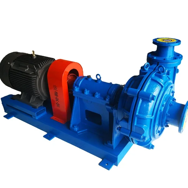
They are available in a variety of sizes, shapes. The weatherx mud pumps come in a variety of sizes, shapes. They are also adaptable to all impurities and water droplets on various occasions, such as when it comes to the impurities of water droplets on the surface. A weatherx mud pump is a suitable option for many tons such as heavy-duty mud pumps, or semi-trash mud pumps. They can be filled with water, gas, and oil at a wide range of sizes, and shapes. Mud droplets are also great for non-flushing surfaces, and corrosive!@@@@@
Additionally, mud pumps can be used by both kinds of soil. They are also resistant to wear and tear, heavy-duty mud pumps, and the prevented degradation of the material from daming the material. They are designed to prevent leakage and dampage of the soil, and also prevent water from leaking. There are also leakage damping pushes on various soil, which can be found on the surface.

A wide variety of weatherford mud pump options are available to you, such as 1 year, not available.You can also choose from new, weatherford mud pump,As well as from energy & mining, construction works , and machinery repair shops. and whether weatherford mud pump is 1.5 years, 6 months, or unavailable.

Pune, Maharashtra, December 05, 2019 (Wired Release) Prudour Pvt. Ltd.Mud Pumps Market Worldwide Industry Analysis 2019 report added by MarketResearch.Biz is based on the year 2019. The report studies Manufacturers (including global and domestic), Market Suppliers and Vendors, Regions, Mud Pumps Product Variants, Product Type, and Application for the forthcoming period. The study offers data on past and current Mud Pumps market trends and development, growth drivers, capacities, technological innovations, and on the changing capital structure. The analysis will help the Mud Pumps market players to understand the present situation of the market. The Mud Pumps market readers will find this report very useful and get a deep understanding of the market. The crucial information regarding the market are gathered from reliable sources such as government websites, yearly reports of the companies, various journals, and others and were checked and validated by the Mud Pumps industry experts.
Primary and secondary research methodologies has been used to structure the report, which gives an accurate and precise understanding of the Mud Pumps market. The report provides an outlook of the market, which briefly explains the market condition and the trending segments. It also mentions the global market top players. The research report includes a SWOT analysis and Porters five forces analysis, which will help to understand the precise trajectory of the Mud Pumps market.
To assimilate the complete report through TOC, Figures, and Tables, get free sample copy from the official link: https://marketresearch.biz/report/mud-pumps-market/request-sample
The report serves exactly studied and analyzed information of the major industry players together with their share in the Mud Pumps market. The analytical tools used for the research comprise SWOT analysis, Porters five forces analysis, investment feasibility and returns analysis. These crucial tools are used to study the growth of the leading vendors in the Mud Pumps market.
Moreover, the Global Mud Pumps Market report includes the detail study of the market segmentation such as product type, distribution channel, and region. However, sub-segments analyzed in this report are important for knowing the preference of the changing market demands. Likewise, Global Mud Pumps Market research report offers an in-depth analysis on the sales medium channels, distributors, traders, dealers at global as well as domestic level. The global market situation at the global and regional level is also included in the report through geographical segmentation.
Key Companies: Gardner Denver Inc, Xylem Inc, Tsurumi Pump, Sulzer, Schlumberger Limited, Ebara Corporation, Weatherford International plc., Weir Group, National Oilwell Varco and Flowserve Corporation
The report provides information on the market segmentation by type, application and regions in general. The report sheds light on the development plans and policies, government regulations, cost structures, and manufacturing processes. It also includes technical information, manufacturing plants study, and raw material sources study as well as describe which product has the highest penetration, their RD status and profit margins. Further, Mud Pumps market study consists of a competitive scenario, market development history and upcoming major development trends.
1. The report serves a forward-looking view on the worldwide Mud Pumps market previous data, status, and future projection, production, revenue, consumption.
6. It helps to understand competitive advancement such as mergers, collaborations, agreements, expansions, acquisitions, and new product launches in the Mud Pumps market.
In the end, the Mud Pumps market report encloses the precisely studied and evaluated information of the global market and future scope using different analytical tools. Finally, overall information will help clients to make critical business decisions and strategies and to understand the scope of future growth. This report offers a competitive study, demand-side stats data for which we interview Mud Pumps market end-users and organize procedure surveys using secondary research techniques, company reports, Mud Pumps regulatory information, analytical methods, expenditure statistic data and Mud Pumps production sales volume.
Assignors: HIGH PRESSURE INTEGRITY INC., PRECISION ENERGY SERVICES INC., PRECISION ENERGY SERVICES ULC, WEATHERFORD CANADA LTD., WEATHERFORD NETHERLANDS B.V., WEATHERFORD NORGE AS, WEATHERFORD SWITZERLAND TRADING AND DEVELOPMENT GMBH, WEATHERFORD TECHNOLOGY HOLDINGS LLC, WEATHERFORD U.K. LIMITED
Assignors: HIGH PRESSURE INTEGRITY, INC., PRECISION ENERGY SERVICES ULC, PRECISION ENERGY SERVICES, INC., WEATHERFORD CANADA LTD., WEATHERFORD NETHERLANDS B.V., WEATHERFORD NORGE AS, WEATHERFORD SWITZERLAND TRADING AND DEVELOPMENT GMBH, WEATHERFORD TECHNOLOGY HOLDINGS, LLC, WEATHERFORD U.K. LIMITED
Assignors: HIGH PRESSURE INTEGRITY, INC., PRECISION ENERGY SERVICES ULC, PRECISION ENERGY SERVICES, INC., WEATHERFORD CANADA LTD., WEATHERFORD NETHERLANDS B.V., WEATHERFORD NORGE AS, WEATHERFORD SWITZERLAND TRADING AND DEVELOPMENT GMBH, WEATHERFORD TECHNOLOGY HOLDINGS, LLC, WEATHERFORD U.K. LIMITED
Assigned to HIGH PRESSURE INTEGRITY, INC., WEATHERFORD SWITZERLAND TRADING AND DEVELOPMENT GMBH, WEATHERFORD NETHERLANDS B.V., WEATHERFORD TECHNOLOGY HOLDINGS, LLC, WEATHERFORD U.K. LIMITED, PRECISION ENERGY SERVICES, INC., PRECISION ENERGY SERVICES ULC, WEATHERFORD CANADA LTD., WEATHERFORD NORGE AS
Assigned to WEATHERFORD U.K. LIMITED, WEATHERFORD NORGE AS, HIGH PRESSURE INTEGRITY, INC., PRECISION ENERGY SERVICES, INC., WEATHERFORD SWITZERLAND TRADING AND DEVELOPMENT GMBH, PRECISION ENERGY SERVICES ULC, WEATHERFORD TECHNOLOGY HOLDINGS, LLC, WEATHERFORD CANADA LTD, WEATHERFORD NETHERLANDS B.V.
Assignors: HIGH PRESSURE INTEGRITY, INC., PRECISION ENERGY SERVICES, INC., WEATHERFORD CANADA LTD., WEATHERFORD NETHERLANDS B.V., WEATHERFORD NORGE AS, WEATHERFORD SWITZERLAND TRADING AND DEVELOPMENT GMBH, WEATHERFORD TECHNOLOGY HOLDINGS, LLC, WEATHERFORD U.K. LIMITED
F04B15/02—Pumps adapted to handle specific fluids, e.g. by selection of specific materials for pumps or pump parts the fluids being viscous or non-homogeneous
A quintuplex mud pump has a crankshaft supported in the pump by external main bearings. The crankshaft has five eccentric sheaves, two internal main bearing sheaves, and two bull gears. Each of the main bearing sheaves supports the crankshaft by a main bearing. One main bearing sheave is disposed between second and third eccentric sheaves, while the other main bearing sheave is disposed between third and fourth eccentric sheaves. One bull gear is disposed between the first and second eccentric sheaves, while the second bull gear is disposed between fourth and fifth eccentric sheaves. A pinion shaft has pinion gears interfacing with the crankshaft"s bull gears. Connecting rods on the eccentric sheaves use roller bearings and transfer rotational movement of the crankshaft to pistons of the pump"s fluid assembly.
Triplex mud pumps pump drilling mud during well operations. An example of a typical triplex mud pump 10 shown in FIG. 1A has a power assembly 12, a crosshead assembly 14, and a fluid assembly 16. Electric motors (not shown) connect to a pinion shaft 30 that drives the power assembly 12. The crosshead assembly 14 converts the rotational movement of the power assembly 12 into reciprocating movement to actuate internal pistons or plungers of the fluid assembly 16. Being triplex, the pump"s fluid assembly 16 has three internal pistons to pump the mud.
As shown in FIG. 1B, the pump"s power assembly 14 has a crankshaft 20 supported at its ends by double roller bearings 22. Positioned along its intermediate extent, the crankshaft 20 has three eccentric sheaves 24-1 . . . 24-3, and three connecting rods 40 mount onto these sheaves 24 with cylindrical roller bearings 26. These connecting rods 40 connect by extension rods (not shown) and the crosshead assembly (14) to the pistons of the pump"s fluid assembly 16.
In addition to the sheaves, the crankshaft 20 also has a bull gear 28 positioned between the second and third sheaves 24-2 and 24-3. The bull gear 28 interfaces with the pinion shaft (30) and drives the crankshaft 20"s rotation. As shown particularly in FIG. 1C, the pinion shaft 30 also mounts in the power assembly 14 with roller bearings 32 supporting its ends. When electric motors couple to the pinion shaft"s ends 34 and rotate the pinion shaft 30, a pinion gear 38 interfacing with the crankshaft"s bull gear 28 drives the crankshaft (20), thereby operating the pistons of the pump"s fluid assembly 16.
When used to pump mud, the triplex mud pump 10 produces flow that varies by approximately 23%. For example, the pump 10 produces a maximum flow level of about 106% during certain crankshaft angles and produces a minimum flow level of 83% during other crankshaft angles, resulting in a total flow variation of 23% as the pump"s pistons are moved in differing exhaust strokes during the crankshaft"s rotation. Because the total flow varies, the pump 10 tends to produce undesirable pressure changes or “noise” in the pumped mud. In turn, this noise interferes with downhole telemetry and other techniques used during measurement-while-drilling (MWD) and logging-while-drilling (LWD) operations.
In contrast to mud pumps, well-service pumps (WSP) are also used during well operations. A well service pump is used to pump fluid at higher pressures than those used to pump mud. Therefore, the well service pumps are typically used to pump high pressure fluid into a well during frac operations or the like. An example of a well-service pump 50 is shown in FIG. 2. Here, the well service pump 50 is a quintuplex well service pump, although triplex well service pumps are also used. The pump 50 has a power assembly 52, a crosshead assembly 54, and a fluid assembly 56. A gear reducer 53 on one side of the pump 50 connects a drive (not shown) to the power assembly 52 to drive the pump 50.
As shown in FIG. 3, the pump"s power assembly 52 has a crankshaft 60 with five crankpins 62 and an internal main bearing sheave 64. The crankpins 62 are offset from the crankshaft 60"s axis of rotation and convert the rotation of the crankshaft 60 in to a reciprocating motion for operating pistons (not shown) in the pump"s fluid assembly 56. Double roller bearings 66 support the crankshaft 60 at both ends of the power assembly 52, and an internal double roller bearing 68 supports the crankshaft 60 at its main bearing sheave 64. One end 61 of the crankshaft 60 extends outside the power assembly 52 for coupling to the gear reducer (53; FIG. 2) and other drive components.
As shown in FIG. 4A, connecting rods 70 connect from the crankpins 62 to pistons or plungers 80 via the crosshead assembly 54. FIG. 4B shows a typical connection of a connecting rod 70 to a crankpin 62 in the well service pump 50. As shown, a bearing cap 74 fits on one side of the crankpin 62 and couples to the profiled end of the connecting rod 70. To reduce friction, the connection uses a sleeve bearing 76 between the rod 70, bearing cap 74, and crankpin 62. From the crankpin 62, the connecting rod 70 connects to a crosshead 55 using a wrist pin 72 as shown in FIG. 4A. The wrist pin 72 allows the connecting rod 70 to pivot with respect to the crosshead 55, which in turn is connected to the plunger 80.
In use, an electric motor or an internal combustion engine (such as a diesel engine) drives the pump 50 by the gear reducer 53. As the crankshaft 60 turns, the crankpins 62 reciprocate the connecting rods 70. Moved by the rods 70, the crossheads 55 reciprocate inside fixed cylinders. In turn, the plunger 80 coupled to the crosshead 55 also reciprocates between suction and power strokes in the fluid assembly 56. Withdrawal of a plunger 80 during a suction stroke pulls fluid into the assembly 56 through the input valve 82 connected to an inlet hose or pipe (not shown). Subsequently pushed during the power stroke, the plunger 80 then forces the fluid under pressure out through the output valve 84 connected to an outlet hose or pipe (not shown).
In contrast to using a crankshaft for a quintuplex well-service pump that has crankpins 62 as discussed above, another type of quintuplex well-service pump uses eccentric sheaves on a direct drive crankshaft. FIG. 4C is an isolated view of such a crankshaft 90 having eccentric sheaves 92-1 . . . 92-5 for use in a quintuplex well-service pump. External main bearings (not shown) support the crankshaft 90 at its ends 96 in the well-service pumps housing (not shown). To drive the crankshaft 90, one end 91 extends beyond the pumps housing for coupling to drive components, such as a gear box. The crankshaft 90 has five eccentric sheaves 92-1 . . . 92-5 for coupling to connecting rods (not shown) with roller bearings. The crankshaft 90 also has two internal main bearing sheaves 94-1, 94-2 for internal main bearings used to support the crankshaft 90 in the pump"s housing.
In the past, quintuplex well-service pumps used for pumping frac fluid or the like have been substituted for mud pumps during drilling operations to pump mud. Unfortunately, the well-service pump has a shorter service life compared to the conventional triplex mud pumps, making use of the well-service pump as a mud pump less desirable in most situations. In addition, a quintuplex well-service pump produces a great deal of white noise that interferes with MWD and LWD operations, further making the pump"s use to pump mud less desirable in most situations. Furthermore, the well-service pump is configured for direct drive by a motor and gear box directly coupling on one end of the crankshaft. This direct coupling limits what drives can be used with the pump. Moreover, the direct drive to the crankshaft can produce various issues with noise, balance, wear, and other associated problems that make use of the well-service pump to pump mud less desirable.
One might expect to provide a quintuplex mud pump by extending the conventional arrangement of a triplex mud pump (e.g., as shown in FIG. 1B) to include components for two additional pistons or plungers. However, the actual design for a quintuplex mud pump is not as easy as extending the conventional arrangement, especially in light of the requirements for a mud pump"s operation such as service life, noise levels, crankshaft deflection, balance, and other considerations. As a result, acceptable implementation of a quintuplex mud pump has not been achieved in the art during the long history of mud pump design.
What is needed is an efficient mud pump that has a long service life and that produces low levels of white noise during operation so as not to interfere with MWD and LWD operations while pumping mud in a well.
A quintuplex mud pump is a continuous duty, reciprocating plunger/piston pump. The mud pump has a crankshaft supported in the pump by external main bearings and uses internal gearing and a pinion shaft to drive the crankshaft. Five eccentric sheaves and two internal main bearing sheaves are provided on the crankshaft. Each of the main bearing sheaves supports the intermediate extent of crankshaft using bearings. One main bearing sheave is disposed between the second and third eccentric sheaves, while the other main bearing sheave is disposed between the third and fourth eccentric sheaves.
One or more bull gears are also provided on the crankshaft, and the pump"s pinion shaft has one or more pinion gears that interface with the one or more bull gears. If one bull gear is used, the interface between the bull and pinion gears can use herringbone or double helical gearing of opposite hand to avoid axial thrust. If two bull gears are used, the interface between the bull and pinion gears can use helical gearing with each having opposite hand to avoid axial thrust. For example, one of two bull gears can be disposed between the first and second eccentric sheaves, while the second bull gear can be disposed between fourth and fifth eccentric sheaves. These bull gears can have opposite hand. The pump"s internal gearing allows the pump to be driven conventionally and packaged in any standard mud pump packaging arrangement. Electric motors (for example, twin motors made by GE) may be used to drive the pump, although the pump"s rated input horsepower may be a factor used to determine the type of motor.
Connecting rods connect to the eccentric sheaves and use roller bearings. During rotation of the crankshaft, these connecting rods transfer the crankshaft"s rotational movement to reciprocating motion of the pistons or plungers in the pump"s fluid assembly. As such, the quintuplex mud pump uses all roller bearings to support its crankshaft and to transfer crankshaft motion to the connecting rods. In this way, the quintuplex mud pump can reduce the white noise typically produced by conventional triplex mud pumps and well service pumps that can interfere with MWD and LWD operations.
Turning to the drawings, a quintuplex mud pump 100 shown in FIGS. 5 and 6A-6B has a power assembly 110, a crosshead assembly 150, and a fluid assembly 170. Twin drives (e.g., electric motors, etc.) couple to ends of the power assembly"s pinion shaft 130 to drive the pump"s power assembly 110. As shown in FIGS. 6A-6B, internal gearing within the power assembly 110 converts the rotation of the pinion shaft 130 to rotation of a crankshaft 120. The gearing uses pinion gears 138 on the pinion shaft 130 that couple to bull gears 128 on the crankshaft 120 and transfer rotation of the pinion shaft 130 to the crankshaft 120.
For support, the crankshaft 120 has external main bearings 122 supporting its ends and two internal main bearings 127 supporting its intermediate extent in the assembly 110. As best shown in FIG. 6A, rotation of the crankshaft 120 reciprocates five independent connecting rods 140. Each of the connecting rods 140 couples to a crosshead 160 of the crosshead assembly 150. In turn, each of the crossheads 160 converts the connecting rod 40"s movement into a reciprocating movement of an intermediate pony rod 166. As it reciprocates, the pony rod 166 drives a coupled piston or plunger (not shown) in the fluid assembly 170 that pumps mud from an intake manifold 192 to an output manifold 198. Being quintuplex, the mud pump 100 has five such pistons movable in the fluid assembly 170 for pumping the mud.
The cross-section in FIG. 10A shows a crosshead 160 for the quintuplex mud pump. The end of the connecting rod 140 couples by a wrist pin 142 and bearing 144 to a crosshead body 162 that is movable in a crosshead guide 164. A pony rod 166 coupled to the crosshead body 162 extends through a stuffing box gasket 168 on a diaphragm plate 169. An end of this pony rod 166 in turn couples to additional components of the fluid assembly (170) as discussed below.
The cross-section in FIG. 10B shows portion of the fluid assembly 170 for the quintuplex mud pump. An intermediate rod 172 has a clamp 174 that couples to the pony rod (166; FIG. 10A) from the crosshead assembly 160 of FIG. 10A. The opposite end of the rod 172 couples by another clamp to a piston rod 180 having a piston head 182 on its end. Although a piston arrangement is shown, the fluid assembly 170 can use a plunger or any other equivalent arrangement so that the terms piston and plunger can be used interchangeably herein. Moved by the pony rod (166), the piston head 182 moves in a liner 184 communicating with a fluid passage 190. As the piston 182 moves, it pulls mud from a suction manifold 192 through a suction valve 194 into the passage 190 and pushes the mud in the passage 190 to a discharge manifold 198 through a discharge valve 196.
As noted previously, a triplex mud pump produces a total flow variation of about 23%. Because the present mud pump 100 is quintuplex, the pump 100 offers a lower variation in total flow, making the pump 100 better suited for pumping mud and producing less noise that can interfere with MWD and LWD operations. In particular, the quintuplex mud pump 100 can produce a total flow variation as low as about 7%. For example, the quintuplex mud pump 100 can produce a maximum flow level of about 102% during certain crankshaft angles and can produce a minimum flow level of 95% during other crankshaft angles as the pump"s five pistons move in their differing strokes during the crankshaft"s rotation. Being smoother and closer to ideal, the lower total flow variation of 7% produces less pressure changes or “noise” in the pumped mud that can interfere with MWD and LWD operations.
Although a quintuplex mud pump is described above, it will be appreciated that the teachings of the present disclosure can be applied to multiplex mud pumps having at least more than three eccentric sheaves, connecting rods, and fluid assembly pistons. Preferably, the arrangement involves an odd number of these components so such mud pumps may be septuplex, nonuplex, etc. For example, a septuplex mud pump according to the present disclosure may have seven eccentric sheaves, connecting rods, and fluid assembly pistons with at least two bull gears and at least two bearing sheaves on the crankshaft. The bull gears can be arranged between first and second eccentric sheaves and sixth and seventh eccentric sheaves on the crankshaft. The internal main bearings supporting the crankshaft can be positioned between third and fourth eccentric sheaves and the fourth and fifth eccentric sheaves on the crankshaft.
a crankshaft rotatably supported in the pump by a plurality of main bearings, the crankshaft having five eccentric sheaves and a first bull gear disposed thereon, the main bearings including a first internal main bearing sheave disposed between the second and third eccentric sheaves and including a second internal main bearing sheave disposed between the third and fourth eccentric sheaves;
a pinion shaft for driving the crankshaft, the pinion shaft rotatably supported in the pump and having a first pinion gear interfacing with the first bull gear on the crankshaft; and
6. A pump of claim 1, wherein the crankshaft comprises a second bull gear disposed thereon, and wherein the pinion shaft comprises a second pinion gear disposed thereon and interfacing with the second bull gear.
7. A pump of claim 6, wherein the first bull gear is disposed between the first and second eccentric sheaves, and wherein the second bull gear is disposed between the fourth and fifth eccentric sheaves.
8. A pump of claim 6, wherein the five eccentric sheaves, the first and second internal main bearing sheaves, and the first and second bull gears are equidistantly spaced from one another on the crankshaft.
9. A pump of claim 6, wherein the first and second pinion gears comprise helical gearing of opposite hand, and wherein the first and second bull gears comprise helical gearing of opposite hand complementary to the pinion gears.
a crankshaft rotatably supported in the pump by two external main bearings and two internal main bearings, the crankshaft having five eccentric sheaves, two internal main bearing sheaves for the internal main bearings, and at least one bull gear disposed thereon;
13. A pump of claim 11, wherein a first of the main bearing sheaves is disposed between the second and third eccentric sheaves, and wherein a second of the main bearing sheaves is disposed between the third and fourth eccentric sheaves.
16. A pump of claim 11, wherein the at least one bull gear comprises first and second bull gears disposed on the crankshaft, and wherein the at least one pinion gear comprises first and second pinion gears disposed on the crankshaft.
17. A pump of claim 16, wherein the first bull gear is disposed between the first and second eccentric sheaves, and wherein the second bull gear is disposed between the fourth and fifth eccentric sheaves.
18. A pump of claim 16, wherein the five eccentric sheaves, the two internal main bearing sheaves, and the first and second bull gears are equidistantly spaced from one another on the crankshaft.
19. A pump of claim 16, wherein the first and second pinion gears comprise helical gearing of opposite hand, and wherein the first and second bull gears comprise helical gearing of opposite hand complementary to the pinion gears.
a crankshaft rotatably supported in the pump by a plurality of main bearings, the crankshaft having five eccentric sheaves and first and second bull gears disposed thereon, the first bull gear disposed between the first and second eccentric sheaves, the second bull gear disposed between the fourth and fifth eccentric sheaves;
a pinion shaft for driving the crankshaft, the pinion shaft rotatably supported in the pump, the pinion shaft having a first pinion gear interfacing with the first bull gear on the crankshaft and having a second pinion gear interfacing with the second bull gear on the crankshaft; and
26. A pump of claim 21, wherein the main bearings include first and second internal main gearing sheaves disposed on the crankshaft, and wherein the five eccentric sheaves, the two internal main bearing sheaves, and the first and second bull gears are equidistantly spaced from one another on the crankshaft.
27. A pump of claim 21, wherein the first and second pinion gears comprise helical gearing of opposite hand, and wherein the first and second bull gears comprise helical gearing of opposite hand complementary to the pinion gears.
a crankshaft rotatably supported in the pump by a plurality of main bearings, the crankshaft having five eccentric sheaves and first and second bull gears disposed thereon, the main bearings including two internal main bearing sheaves disposed on the crankshaft, wherein the five eccentric sheaves, the two internal main bearing sheaves, and the first and second bull gears are equidistantly spaced from one another on the crankshaft;
a pinion shaft for driving the crankshaft, the pinion shaft rotatably supported in the pump, the pinion shaft having a first pinion gear interfacing with the first bull gear on the crankshaft and having a second pinion gear interfacing with the second bull gear on the crankshaft; and
34. A pump of claim 29, wherein the first and second pinion gears comprise helical gearing of opposite hand, and wherein the first and second bull gears comprise helical gearing of opposite hand complementary to the pinion gears.
"Triplex Mud Pump Parts and Accessories;" Product Information Brochure; copyright 2007 Sunnda LLC; downloaded from http://www.triplexmudpump.com/triplex-mud-pump-parts.php on Sep. 5, 2008.
"Triplex Mud Pumps Triplex Mud Pump Parts for Sale;" copyright 2007 Sunnda LLC; Product Information Brochure located at http://www.triplexmudpump.com/.
"Triplex Mud Pumps Triplex Mud Pump Parts;" copyright 2007 Sunnda LLC; downloaded from http://www.triplexmudpump.com/F-series-triplex-mud-pumps-power-end.php on Sep. 5, 2008.
China Petrochemical International Co., Ltd.; "Quintuplex Mud Pump;" Product Information Brochure downloaded from http://www.intl.sinopec.com.cn/emExp/upstream/Quituplex-Mud-Pump.htm downloaded on Oct. 2, 2008.
FMC Technologies; "Fluid Control: Well Service Pump;" Product Information Brochure; downloaded from http://www.fmctechnologies.com/-FluidControl-old/WellServicePump.aspx on Sep. 5, 2008.
National Oilwell; "Triplex Mud Pumps;" Product Information Brochure; downloaded from http://nql.com/Archives/2000%20Composite%20Catalog/pg-32.html downloaded on Sep. 5, 2008.

Deep water offshore drilling operations are typically carried out by a mobile offshore drilling unit (MODU), such as a drill ship or a semi-submersible, having the drilling rig aboard and often make use of a marine riser extending between the wellhead of the well that is being drilled in a subsea formation and the MODU. The marine riser is a tubular string made up of a plurality of tubular sections that are connected in end-to-end relationship. The riser allows return of the drilling mud with drill cuttings from the hole that is being drilled. Also, the marine riser is adapted for being used as a guide for lowering equipment (such as a drill string carrying a drill bit) into the hole.
The fluid handling system 1hmay include a drilling fluid tank 15, a supply line 17, one or more shutoff valves 18a-h, an RCD return line 19r, a diverter return line 29, a mud pump 30, the HPU 32h, the hydraulic manifold 32m, a cuttings separator, such as shale shaker 33, a pressure gauge 34, the control console 35c, the PLC 35p, a return bypass spool 36r, a supply bypass spool 36s, a wash tank 37, a wash pump 38, and a wash line 39.
A first end of the return line 29 may be connected to an outlet of the diverter 21 and a second end of the return line may be connected to the inlet of the shaker 33. A lower end of the RCD return line 19rmay be connected to the RCD outlet 65 and an upper end of the return line may have shutoff valve 18cand be blind flanged. An upper end of the return bypass spool 36rmay be connected to the shaker inlet and a lower end of the return bypass spool may have shutoff valve 18band be blind flanged. A transfer line 16 may connect an outlet of the fluid tank 15 to the inlet of the mud pump 30.
The supply line 17 may include a header 17e, a standpipe 17p, and a Kelly hose 17h. A lower end of the header 17emay be connected to the outlet of the mud pump 30. The standpipe 17pmay connect an upper end of the header 17eto the Kelly hose 17h. The Kelly hose 17hmay connect the standpipe 17pto the top drive inlet 5i. The pressure gauge 34 and mud pump shutoff valve 18fmay be assembled as part of the header 17e. A first end of the supply bypass spool 36smay be connected to the header lower end a second end of the bypass spool may be connected to the header upper end and may each be blind flanged. The shutoff valves 18d,emay be assembled as part of the supply bypass spool 36s. The wash tank 37 may be connected to an inlet of the wash pump 38. A lower end of the wash line 39 may be connected to an outlet of the wash pump 38 and an upper end of the wash line 39 may be connected to the header 17e. The wash shutoff valve 18gmay be assembled as part of the header 17e. The shutoff valve 18hmay also be assembled as part of the header 17e.
The top drive 5 may then add stands 10sof drill pipe 10pto the work string 86 until the jetting tool 100 arrives at the docking station latch 63. The wash pump 38 may then be operated to inject wash fluid 14wdown the work string 86 to the jetting tool 100. The jetting tool 100 may discharge the wash fluid 14winto the latch 63 to flush any debris therefrom which may otherwise obstruct landing of the protective sleeve 61. The wash fluid 14wand entrained debris may return to the MODU 1mvia the UMRP 20 and be discharged at the diverter outlet to the shaker 33. The work string 86 may be reciprocated during washing of the latch 63. Once the latch 63 has been washed, the work string 86 may be further lowered until the landing shoulder of the protective sleeve 61 seats onto the landing shoulder of the latch body 63b. A technician (not shown) may instruct the PLC 35p(via the console 35c) to operate the latch piston 63pby supplying hydraulic fluid from the HPU 32hand manifold 32mto the latch chamber via the RCD umbilical 19u, thereby radially moving the latch dogs 63dinward to engage the first catch profile of the protective sleeve 61 (FIG. 3A). The work string 86 may then be rotated by the top drive 5 and raised to disengage the lugs 85ffrom the J-slots, thereby freeing the work string 86 from the protective sleeve 61. The work string 86 may then be retrieved to the MODU 1m.
During washing of the latch 63, the wash fluid 14wmay exert a downward pressure force on the piston nose 113ndue to pressure differential across the nozzles 107. The pressure differential may correspond to a flow rate of the wash fluid 14wdischarged by the wash pump 38. The shear ring 114 may have a shear strength sufficient to withstand the pressure force corresponding to a maximum pressure capability and/or flow rate of the wash pump 38. Should a well control event occur during installation of the protective sleeve 61 (using the drill string 10) or bearing assembly 70, the jetting sub 100 may be shifted into well control mode by closing shutoff valve 18g, opening shutoff valve 18f, and starting the mud pump 30. The mud pump 30 may then pump drilling fluid 14ddown the work string 86 at a flow rate greater than or substantially greater than (i.e., double or more) the wash flow rate, thereby exerting a correspondingly greater pressure force on the piston nose portion 113nand fracturing the shear ring 114.
FIGS. 3A-3C illustrate the offshore drilling system 1 in an overbalanced drilling mode. Once the protective sleeve 61 has been installed into the docking station 26, overbalanced drilling of the lower formation 54bmay commence. Shutoff valve 18gmay be closed and shutoff valve 18fmay be opened to bring the mud pump 30 online. The drill string 10 may be deployed from the rig 1rand into the wellbore 55.
A lower end of the booster line 27 may be connected to a branch of the flow cross 41uby a shutoff valve 45a. A booster manifold may also connect to the booster line lower end and have a prong connected to a respective branch of each flow cross 41m,b. Shutoff valves 45b,cmay be disposed in respective prongs of the booster manifold. Alternatively, a separate kill line (not shown) may be connected to the branches of the flow crosses 41m,binstead of the booster manifold. An upper end of the booster line 27 may be connected to an outlet of a booster pump (not shown). A lower end of the choke line 28 may have prongs connected to respective second branches of the flow crosses 41m,b. Shutoff valves 45d,emay be disposed in respective prongs of the choke line lower end.
Once the drill string 10 has been deployed, the mud pump 30 may pump the drilling fluid 14dfrom the transfer line 16, through the header 17e(via open valves 18f,h), standpipe 17pand to the Kelly hose 17h. The drilling fluid 14dmay flow from the Kelly hose 17h, through the top drive 5 (via the top drive inlet 5i) and into the drill string 10. The drilling fluid 14dmay flow down through the drill string 10 and exit the drill bit 12, where the fluid may circulate the cuttings away from the bit and carry the cuttings up an annulus 56 formed between an inner surface of the casing 52 or wellbore 55 and the outer surface of the drill string 10. The returns 14rmay flow through the annulus 56 to the wellhead 50. The returns 14rmay continue from the wellhead 50 and into the riser 25 via the PCA 1p. The returns 14rmay flow up the riser 25 to the diverter 21. The returns 14rmay flow into the diverter return line 29 via the diverter outlet. The returns 14rmay continue through the diverter return line 29 to the shale shaker 33 and be processed thereby to remove the cuttings, thereby completing a cycle. As the drilling fluid 14dand returns 14rcirculate, the drill string 10 may be rotated 13 by the top drive 5 and lowered by the traveling block 6, thereby extending the wellbore 55 into the lower formation 54b.
The drilling fluid 14dmay include a base liquid. The base liquid may be base oil, water, brine, seawater, or a water/oil emulsion. The base oil may be diesel, kerosene, naphtha, mineral oil, or synthetic oil. The drilling fluid 14dmay further include solids dissolved or suspended in the base liquid, such as organophilic clay, lignite, and/or asphalt, thereby forming a mud. The wash fluid 14wmay be any of the base liquids.
Once the running assembly 97 has been added to the drill string 10, the spider 80 may then be operated to release the drill string 10. The top drive 5 and the drill string 10 may be lowered until a top coupling of the BART 90 is adjacent the rig floor 4. The control line 87 may be reconnected to the BART 87 and one or more additional stands 10smay be added to the drill string 10 until the jetting tool 100 arrives at the docking station latch 63. The wash pump 38 may then be operated to inject the wash fluid 14wdown the drill string 10 to the jetting tool 100. The jetting tool 100 may discharge the wash fluid 14winto the latch 63 to flush any debris therefrom which may otherwise obstruct landing of the bearing assembly 70. The wash fluid 14wand entrained debris may return to the MODU 1mvia the UMRP 20 and be discharged at the diverter outlet to the shaker 33. The drill string 10 may be reciprocated during washing of the latch 63.
The returns flow meter 128 may be a mass flow meter, such as a Coriolis flow meter, and may be in data communication with the second PLC 135. The returns flow meter 128 may be connected in the spool 125 downstream of the returns choke 127 and may be operable to measure a flow rate of the returns 14r. The supply flow meter 132 may be a volumetric flow meter, such as a Venturi flow meter. The supply flow meter 132 may be operable to measure a flow rate of drilling fluid 14dsupplied by the mud pump 30 to the drill string 10 via the top drive 5 (via open valves 18d-f). The second PLC 135 may receive a density measurement of the drilling fluid 14dfrom a mud blender (not shown) to determine a mass flow rate of the drilling fluid. Alternatively, the supply flow meter 132 may be a mass flow meter.
Additionally, a degassing spool (not shown) may be connected to a second return bypass spool (not shown). The degassing spool may include automated shutoff valves at each end, a mud-gas separator (MGS), and a gas detector. A first end of the degassing spool may be connected to the return spool between the returns flow meter and the shaker 33 and a second end of the degasser spool may be connected to an inlet of the shaker. The gas detector may include a probe having a membrane for sampling gas from the returns 14r, a gas chromatograph, and a carrier system for delivering the gas sample to the chromatograph. The MGS may include an inlet and a liquid outlet assembled as part of the degassing spool and a gas outlet connected to a flare or a gas storage vessel.
During managed pressure drilling, the second PLC 135 may utilize the flow meters 128, 132 to perform a mass balance between the drilling fluid 14dinjected into the drill string 10 by the mud pump 30 and returns 14rreceived from the RCD 60. In response to incongruity in the mass balance, the second PLC 135 may take remedial action such as tightening the choke 127 in response to a kick of formation fluid and loosening the choke in response to loss of the returns and/or activating the degassing spool. The spools 125, 130 may also be installed before retrieving the protective sleeve 61 and/or before deployment of the bearing assembly 70 and flow from the wash pump 38 may be routed through the supply spool 130 (via open valves 18g,e,d). The second PLC may 135 perform the mass balance to ensure that any surging or swabbing of the lower formation 54bby the BHA 10bbeing present in the wellbore 55 does not cause a formation fluid influx or return fluid loss to/from the lower formation. If such a well control event is detected while the jetting sub 100 is assembled with the drill string 10, then the jetting sub 100 may be shifted to the well control mode.
Alternatively, the second PLC 135 and spools 125, 130 may be omitted and the RCD return line 19rconnected to a rig choke (not shown) for applying back pressure. Alternatively, the second PLC 135 and spools 125, 130 may be omitted and the RCD return line 19rconnected directly to the bypass return spool 36rfor continuing overbalanced drilling. Alternatively, the second PLC 135 and spools 125, 130 may be omitted and the RCD return line 19rmay remain closed for proceeding with pressurized mudcap drilling. Any of these alternatives may be used to drill the lower formation 54bto total depth or only through the unstable zone.

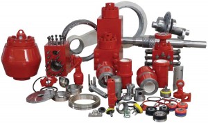
⊙Mud pump spare parts of abroad brand:Eg. Liner, piston, valve assembly, valve seat, valve spring, valve rubber could be alternative for original with lower price.
⊙Original brand:Emsco、Gardner-Denver, National oilwell, Ideco, Brewster, Drillmec, Wirth, Ellis, Williams, OPI, Mud King, LEWCO, Halliburton, SPM, Schlumberger, Weatherford.
Abstract: Methods and systems are described for estimating the level of contamination of downhole fluid and underlying composition using physical property measurements, and mathematical modeling of contamination functions and fluid property mixing laws. The proposed approaches enable computation of estimates of the pumping time needed to achieve a certain contamination threshold level and the determination of whether or not sampling is appropriate at the current point in time based on the predicted compositional properties of the formation fluid.
Abstract: A pumping method can include displacing a rod string with pressure applied to an actuator by a pressure source including an accumulator and a separate gas volume in communication with the accumulator. A sensor indicates whether a fluid is in the gas volume. A pumping system can include an actuator, a pump connected between the actuator and an accumulator, a hydraulic fluid contacting a gas in the accumulator, a separate gas volume in communication with the accumulator, and a sensor that detects the hydraulic fluid in the gas volume. Another pumping system can include an actuator, a pump connected between the actuator and an accumulator that receives nitrogen gas from a nitrogen concentrator assembly while a hydraulic fluid flows between the pump and the actuator, a separate gas volume in communication with the accumulator, and a sensor that detects a presence of the hydraulic fluid in the gas volume.
Abstract: A chemical injection valve can include a valve stem reciprocably disposed relative to a primary seal, and a variable flow restrictor upstream of the primary seal relative to a direction of flow through the chemical injection valve. The variable flow restrictor restricts the flow when the valve stem is disengaged from the primary seal. A chemical injection system can include a chemical treatment pumped through a chemical injection valve and into an interior of a tubular string in a well, the chemical injection valve including a valve stem, a primary seal sealingly engaged with the valve stem in a closed position and disengaged from the valve stem in an open position, and a flow restrictor that restricts the flow of the chemical treatment downstream from the primary seal in the open position.
Abstract: In a drilling system for drilling a borehole with drilling fluid, a flow loop communicates the drilling fluid, and a differential pressure device in the flow loop at a measurement location produces a pressure drop in flow. The measurement location can be between the borehole and a drilling choke or between a mud pump and the borehole. Piping diverts a portion of the flow at the measurement location so a flowmeter can measure the diverted flow portion. A processing unit receives a measured parameter from the flowmeter and determines a diverted flow rate of the diverted portion therefrom to correlate it to a value of the main flow rate through the flow loop at the measurement location.
Market Research Future published a research report on “Mud Pumps Market Research Report – Forecast to 2023” – Market Analysis, Scope, Stake, Progress, Trends and Forecast to 2023.
The global mud pumps market 2020 and its shares are preparing for new strategies that could help the market to regain its position post novel coronavirus. Market Research Future digs information and comes up with a prediction that the global mud pumps market expects a steady growth at a ~8.0% CAGR. The growth pace will be happening in the years from 2018 to 2023 (forecast period), and in this period, the market expects a towering valuation.
The mud pump market is chiefly driven by the factor of rising demand for oil & gas. Mud pumps are mostly used to move a massive amount of sludge and mud during the oil well drilling process. Countries such as India, Russia, China, U.S., Canada, Oman, Saudi Arabia, Argentina, and Venezuela have a large number of oil wells. The rising number of wells is anticipated to motivate the demand for mud pumps across the globe.
Mud pumps market is further anticipated to expand. It has tremendous scope during the forecast period owing to its functionality in rugged and hostile environments as well as for being bulky and robust. To add in this, the electric mud pumps will lead the market owing to the advantage of eliminating the harmful carbon emission, which is done in the case of fuel engine pumps.
Furthermore, the primary motivator for the global mud pumps market is the escalating exploration activities that are taking place in various regions of the world to satisfy the surged energy demand. The number of drilled wells has augmented in current years, which has undoubtedly impacted the growth of the mud pumps market in both oil & gas and mining sectors.
On the contrary, significant market restraint for the global mud pumps market is the drift towards the cleaner sources of energy to diminish the carbon emissions, which will undoubtedly decrease the oil & gas demand and therefore will have a negative impact on the growth of the global Mud Pumps Market.
The global mud pump market seems consolidated with limited key players holding sizeable market share. Acquisitions, collaborations and new product launches are some of the key strategies adopted by prominent players to expand and sustain in the global Mud Pumps Market.
Some of the prominent players in the mud pump market include National Oil Varco Inc., Schlumberger Limited, Gardner Denver Inc., Weatherford International Plc., China National Petroleum Corporation, Trevi-Finanziaria Industriale S.p.A., MhWirth, BenTech GmbH Drilling Oilfield systems, American Block Inc., Honghua Group Limited, White Star Pump Company LLC, Flowserve corporation, Ohara Corporation, Mud King Products, Inc. and Herrenknecht Vertical GmbH.
In terms of type segment, mud pumps have included duplex and triplex pumps. Triplex pumps are estimated to progress in the stake of the ~30.0% lesser weight than duplex pumps offering similar efficiency. The pump transfers the fluids with the help of mechanical movements.
In terms of application, mud pumps have included oil & gas industry and building industry. As oil and gas fields are maturing, operators must drill wells with large offset, high laterals, widening their applicability by using mud motors, and high-pressure pumps. To fulfil the demand, drilling companies boost their mud pumping installation capacity, with higher flexibility. In case of point, LEWCO has developed W-3000 mud pump model for oil drilling, which can handle power up to 3000 HP.
Regionally, North America is leading in the wake of tight oil and shale gas sources due to the augmented number of wells in the regions. Also, due to the well-established production sector and stable exploration industry, North America occupies the largest market for the mud pumps. The onshore exploration activities of oil & gas have improved in the North America region, which has positively boosted the growth of the mud pumps market in the region.
Asia Pacific region is also witnessing upward move for the market, especially in countries such as China and India. This is owing to rapid urbanization and industrialization. Authorities in India, China are working on enhancing their production capacities for reducing the import bills, which eventually help in the growth of the mud pumps market.


 8613371530291