
weatherford mud pump parts free sample

Mud-Pump Gear Sets . . . . . . . . . . . . . . . . . . . . . . . . . . . . . . . . . . . . . . . . . . . . . . . . . . . . . . . . . . . . . . . . . 13
Weatherford products and services are subject to the Company’s standard terms and conditions, available on request or at weatherford.com. For more information contact an authorized Weatherford representative. Unless noted
otherwise, trademarks and service marks herein are the property of Weatherford. Specifications are subject to change without notice. Weatherford sells its products and services in accordance with the terms and conditions set

Weatherford products and services are subject to the Company’s standard terms and conditions, available on request or at weatherford.com. For more information contact an authorized Weatherford representative. Unless noted
otherwise, trademarks and service marks herein are the property of Weatherford and may be registered in the United States and/or other countries. Weatherford products named herein may be protected by one or more U.S. and/or
foreign patents. For more information, contact patents@weatherford.com. Specifications are subject to change without notice. Weatherford sells its products and services in accordance with the terms and conditions set forth in the

⊙Mud pump spare parts of abroad brand:Eg. Liner, piston, valve assembly, valve seat, valve spring, valve rubber could be alternative for original with lower price.
⊙Original brand:Emsco、Gardner-Denver, National oilwell, Ideco, Brewster, Drillmec, Wirth, Ellis, Williams, OPI, Mud King, LEWCO, Halliburton, SPM, Schlumberger, Weatherford.
A wide variety of weatherford mud pump options are available to you, such as 1 year, not available.You can also choose from new, weatherford mud pump,As well as from energy & mining, construction works , and machinery repair shops. and whether weatherford mud pump is 1.5 years, 6 months, or unavailable.

A wide variety of mud pump weatherford options are available to you, such as 1 year, not available.You can also choose from new, mud pump weatherford,As well as from energy & mining, construction works , and machinery repair shops. and whether mud pump weatherford is 1.5 years, 6 months, or unavailable.

Merit Pump and Equipment Company is your direct Weatherford pump distributor. We offer you the complete line of Weatherford reciprocating pumps, including triplex and quintuplex. We can assist you in all your pump service needs. If you are looking for Weatherford pump repair or supplies, we are the specialist team you can count on every time.
Established in 1990, our facility in Wooster, Ohio includes a complete pump repair service center for your major or minor repairs. We also have a knowledgeable sales department ready to answer any of your questions and supply you with the right Weatherford pump equipment and guidance. Our highly trained specialists will work with you to understand your requirements and match you to a specific pump application. We will size the right pump for you and provide ongoing support.
We are a dependable, experienced Weatherford pump service and supply center, & an official Weatherford pump distributor. We are ready to assist you with any inquiry.
Weatherford T-Series and W-Series are versatile pumps, offered in a variety of material and design options that enable them to be used in a wide range of applications. The Weatherford pumps cast iron power frame ensures robust, fatigue-free durability and excellent wear resistance of moving surfaces. The fluid cylinders are made from either forged 4140 carbon steel, 2205 duplex stainless-steel, or 955 cast nickel-aluminum-bronze materials for increased durability and extended life.
Critical components like the crankshaft, connecting rods, crossheads, and bearings are larger than the industry-standards. This enables them to withstand continuous duty service and harsh operating conditions. Weatherford provides tungsten-carbide, coated plungers as standard.
Weatherford offers optional solid ceramic, or ceramic-coated plungers on request for special applications with pumping abrasive or corrosive fluids for superior durability. The oil trough is designed to evenly lubricate the crossheads and wrist-pin bearings during operation to reduce wear and extend component life. A variety of packing arrangements are available to meet the requirements of any application. Weatherford pumps are API-674 compliant upon request.
The Weatherford W-Series triplex and quintuplex plunger pumps are rated for flows from 6 GPM to as high as 688 GPM intermittent duty (533 GPM continuous duty) with pressure ranges from 600 up to 5,000 PSI.
The Weatherford’s T-Series triplex plunger pumps are smaller pumps rated for flows from 0.50 GPM to 85 GPM intermittent duty (or 56 GPM continuous duty) with pressure ranges from 600 up to 5,000 PSI.
The Weatherford’s T-Series triplex plunger pumps are smaller pumps rated for flows from 0.50 GPM to 85 GPM intermittent duty (or 56 GPM continuous duty) with pressure ranges from 600 up to 5,000 PSI. These pumps are offered with carbon steel or duplex stainless-steel fluid end cylinders.
If you need Weatherford pump services, including repair and equipment, please contact us today. We will provide you with decades worth of guidance on your current Weatherford pump or help with your future product. Our specialists are eager to work with you. Call us today at 800-700-8265.

Assignors: HIGH PRESSURE INTEGRITY INC., PRECISION ENERGY SERVICES INC., PRECISION ENERGY SERVICES ULC, WEATHERFORD CANADA LTD., WEATHERFORD NETHERLANDS B.V., WEATHERFORD NORGE AS, WEATHERFORD SWITZERLAND TRADING AND DEVELOPMENT GMBH, WEATHERFORD TECHNOLOGY HOLDINGS LLC, WEATHERFORD U.K. LIMITED
Assignors: HIGH PRESSURE INTEGRITY, INC., PRECISION ENERGY SERVICES ULC, PRECISION ENERGY SERVICES, INC., WEATHERFORD CANADA LTD., WEATHERFORD NETHERLANDS B.V., WEATHERFORD NORGE AS, WEATHERFORD SWITZERLAND TRADING AND DEVELOPMENT GMBH, WEATHERFORD TECHNOLOGY HOLDINGS, LLC, WEATHERFORD U.K. LIMITED
Assignors: HIGH PRESSURE INTEGRITY, INC., PRECISION ENERGY SERVICES ULC, PRECISION ENERGY SERVICES, INC., WEATHERFORD CANADA LTD., WEATHERFORD NETHERLANDS B.V., WEATHERFORD NORGE AS, WEATHERFORD SWITZERLAND TRADING AND DEVELOPMENT GMBH, WEATHERFORD TECHNOLOGY HOLDINGS, LLC, WEATHERFORD U.K. LIMITED
Assigned to HIGH PRESSURE INTEGRITY, INC., WEATHERFORD SWITZERLAND TRADING AND DEVELOPMENT GMBH, WEATHERFORD NETHERLANDS B.V., WEATHERFORD TECHNOLOGY HOLDINGS, LLC, WEATHERFORD U.K. LIMITED, PRECISION ENERGY SERVICES, INC., PRECISION ENERGY SERVICES ULC, WEATHERFORD CANADA LTD., WEATHERFORD NORGE AS
Assigned to WEATHERFORD U.K. LIMITED, WEATHERFORD NORGE AS, HIGH PRESSURE INTEGRITY, INC., PRECISION ENERGY SERVICES, INC., WEATHERFORD SWITZERLAND TRADING AND DEVELOPMENT GMBH, PRECISION ENERGY SERVICES ULC, WEATHERFORD TECHNOLOGY HOLDINGS, LLC, WEATHERFORD CANADA LTD, WEATHERFORD NETHERLANDS B.V.
Assignors: HIGH PRESSURE INTEGRITY, INC., PRECISION ENERGY SERVICES, INC., WEATHERFORD CANADA LTD., WEATHERFORD NETHERLANDS B.V., WEATHERFORD NORGE AS, WEATHERFORD SWITZERLAND TRADING AND DEVELOPMENT GMBH, WEATHERFORD TECHNOLOGY HOLDINGS, LLC, WEATHERFORD U.K. LIMITED
F04B15/02—Pumps adapted to handle specific fluids, e.g. by selection of specific materials for pumps or pump parts the fluids being viscous or non-homogeneous
A quintuplex mud pump has a crankshaft supported in the pump by external main bearings. The crankshaft has five eccentric sheaves, two internal main bearing sheaves, and two bull gears. Each of the main bearing sheaves supports the crankshaft by a main bearing. One main bearing sheave is disposed between second and third eccentric sheaves, while the other main bearing sheave is disposed between third and fourth eccentric sheaves. One bull gear is disposed between the first and second eccentric sheaves, while the second bull gear is disposed between fourth and fifth eccentric sheaves. A pinion shaft has pinion gears interfacing with the crankshaft"s bull gears. Connecting rods on the eccentric sheaves use roller bearings and transfer rotational movement of the crankshaft to pistons of the pump"s fluid assembly.
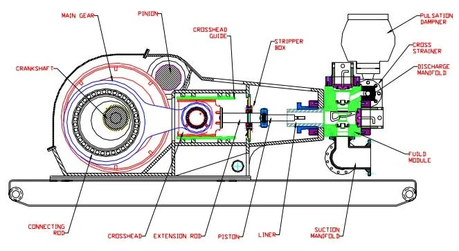
Triplex mud pumps pump drilling mud during well operations. An example of a typical triplex mud pump 10 shown in FIG. 1A has a power assembly 12, a crosshead assembly 14, and a fluid assembly 16. Electric motors (not shown) connect to a pinion shaft 30 that drives the power assembly 12. The crosshead assembly 14 converts the rotational movement of the power assembly 12 into reciprocating movement to actuate internal pistons or plungers of the fluid assembly 16. Being triplex, the pump"s fluid assembly 16 has three internal pistons to pump the mud.
As shown in FIG. 1B, the pump"s power assembly 14 has a crankshaft 20 supported at its ends by double roller bearings 22. Positioned along its intermediate extent, the crankshaft 20 has three eccentric sheaves 24-1 . . . 24-3, and three connecting rods 40 mount onto these sheaves 24 with cylindrical roller bearings 26. These connecting rods 40 connect by extension rods (not shown) and the crosshead assembly (14) to the pistons of the pump"s fluid assembly 16.
In addition to the sheaves, the crankshaft 20 also has a bull gear 28 positioned between the second and third sheaves 24-2 and 24-3. The bull gear 28 interfaces with the pinion shaft (30) and drives the crankshaft 20"s rotation. As shown particularly in FIG. 1C, the pinion shaft 30 also mounts in the power assembly 14 with roller bearings 32 supporting its ends. When electric motors couple to the pinion shaft"s ends 34 and rotate the pinion shaft 30, a pinion gear 38 interfacing with the crankshaft"s bull gear 28 drives the crankshaft (20), thereby operating the pistons of the pump"s fluid assembly 16.
When used to pump mud, the triplex mud pump 10 produces flow that varies by approximately 23%. For example, the pump 10 produces a maximum flow level of about 106% during certain crankshaft angles and produces a minimum flow level of 83% during other crankshaft angles, resulting in a total flow variation of 23% as the pump"s pistons are moved in differing exhaust strokes during the crankshaft"s rotation. Because the total flow varies, the pump 10 tends to produce undesirable pressure changes or “noise” in the pumped mud. In turn, this noise interferes with downhole telemetry and other techniques used during measurement-while-drilling (MWD) and logging-while-drilling (LWD) operations.
In contrast to mud pumps, well-service pumps (WSP) are also used during well operations. A well service pump is used to pump fluid at higher pressures than those used to pump mud. Therefore, the well service pumps are typically used to pump high pressure fluid into a well during frac operations or the like. An example of a well-service pump 50 is shown in FIG. 2. Here, the well service pump 50 is a quintuplex well service pump, although triplex well service pumps are also used. The pump 50 has a power assembly 52, a crosshead assembly 54, and a fluid assembly 56. A gear reducer 53 on one side of the pump 50 connects a drive (not shown) to the power assembly 52 to drive the pump 50.
As shown in FIG. 3, the pump"s power assembly 52 has a crankshaft 60 with five crankpins 62 and an internal main bearing sheave 64. The crankpins 62 are offset from the crankshaft 60"s axis of rotation and convert the rotation of the crankshaft 60 in to a reciprocating motion for operating pistons (not shown) in the pump"s fluid assembly 56. Double roller bearings 66 support the crankshaft 60 at both ends of the power assembly 52, and an internal double roller bearing 68 supports the crankshaft 60 at its main bearing sheave 64. One end 61 of the crankshaft 60 extends outside the power assembly 52 for coupling to the gear reducer (53; FIG. 2) and other drive components.
As shown in FIG. 4A, connecting rods 70 connect from the crankpins 62 to pistons or plungers 80 via the crosshead assembly 54. FIG. 4B shows a typical connection of a connecting rod 70 to a crankpin 62 in the well service pump 50. As shown, a bearing cap 74 fits on one side of the crankpin 62 and couples to the profiled end of the connecting rod 70. To reduce friction, the connection uses a sleeve bearing 76 between the rod 70, bearing cap 74, and crankpin 62. From the crankpin 62, the connecting rod 70 connects to a crosshead 55 using a wrist pin 72 as shown in FIG. 4A. The wrist pin 72 allows the connecting rod 70 to pivot with respect to the crosshead 55, which in turn is connected to the plunger 80.
In use, an electric motor or an internal combustion engine (such as a diesel engine) drives the pump 50 by the gear reducer 53. As the crankshaft 60 turns, the crankpins 62 reciprocate the connecting rods 70. Moved by the rods 70, the crossheads 55 reciprocate inside fixed cylinders. In turn, the plunger 80 coupled to the crosshead 55 also reciprocates between suction and power strokes in the fluid assembly 56. Withdrawal of a plunger 80 during a suction stroke pulls fluid into the assembly 56 through the input valve 82 connected to an inlet hose or pipe (not shown). Subsequently pushed during the power stroke, the plunger 80 then forces the fluid under pressure out through the output valve 84 connected to an outlet hose or pipe (not shown).
In contrast to using a crankshaft for a quintuplex well-service pump that has crankpins 62 as discussed above, another type of quintuplex well-service pump uses eccentric sheaves on a direct drive crankshaft. FIG. 4C is an isolated view of such a crankshaft 90 having eccentric sheaves 92-1 . . . 92-5 for use in a quintuplex well-service pump. External main bearings (not shown) support the crankshaft 90 at its ends 96 in the well-service pumps housing (not shown). To drive the crankshaft 90, one end 91 extends beyond the pumps housing for coupling to drive components, such as a gear box. The crankshaft 90 has five eccentric sheaves 92-1 . . . 92-5 for coupling to connecting rods (not shown) with roller bearings. The crankshaft 90 also has two internal main bearing sheaves 94-1, 94-2 for internal main bearings used to support the crankshaft 90 in the pump"s housing.
In the past, quintuplex well-service pumps used for pumping frac fluid or the like have been substituted for mud pumps during drilling operations to pump mud. Unfortunately, the well-service pump has a shorter service life compared to the conventional triplex mud pumps, making use of the well-service pump as a mud pump less desirable in most situations. In addition, a quintuplex well-service pump produces a great deal of white noise that interferes with MWD and LWD operations, further making the pump"s use to pump mud less desirable in most situations. Furthermore, the well-service pump is configured for direct drive by a motor and gear box directly coupling on one end of the crankshaft. This direct coupling limits what drives can be used with the pump. Moreover, the direct drive to the crankshaft can produce various issues with noise, balance, wear, and other associated problems that make use of the well-service pump to pump mud less desirable.
One might expect to provide a quintuplex mud pump by extending the conventional arrangement of a triplex mud pump (e.g., as shown in FIG. 1B) to include components for two additional pistons or plungers. However, the actual design for a quintuplex mud pump is not as easy as extending the conventional arrangement, especially in light of the requirements for a mud pump"s operation such as service life, noise levels, crankshaft deflection, balance, and other considerations. As a result, acceptable implementation of a quintuplex mud pump has not been achieved in the art during the long history of mud pump design.
What is needed is an efficient mud pump that has a long service life and that produces low levels of white noise during operation so as not to interfere with MWD and LWD operations while pumping mud in a well.
A quintuplex mud pump is a continuous duty, reciprocating plunger/piston pump. The mud pump has a crankshaft supported in the pump by external main bearings and uses internal gearing and a pinion shaft to drive the crankshaft. Five eccentric sheaves and two internal main bearing sheaves are provided on the crankshaft. Each of the main bearing sheaves supports the intermediate extent of crankshaft using bearings. One main bearing sheave is disposed between the second and third eccentric sheaves, while the other main bearing sheave is disposed between the third and fourth eccentric sheaves.
One or more bull gears are also provided on the crankshaft, and the pump"s pinion shaft has one or more pinion gears that interface with the one or more bull gears. If one bull gear is used, the interface between the bull and pinion gears can use herringbone or double helical gearing of opposite hand to avoid axial thrust. If two bull gears are used, the interface between the bull and pinion gears can use helical gearing with each having opposite hand to avoid axial thrust. For example, one of two bull gears can be disposed between the first and second eccentric sheaves, while the second bull gear can be disposed between fourth and fifth eccentric sheaves. These bull gears can have opposite hand. The pump"s internal gearing allows the pump to be driven conventionally and packaged in any standard mud pump packaging arrangement. Electric motors (for example, twin motors made by GE) may be used to drive the pump, although the pump"s rated input horsepower may be a factor used to determine the type of motor.
Connecting rods connect to the eccentric sheaves and use roller bearings. During rotation of the crankshaft, these connecting rods transfer the crankshaft"s rotational movement to reciprocating motion of the pistons or plungers in the pump"s fluid assembly. As such, the quintuplex mud pump uses all roller bearings to support its crankshaft and to transfer crankshaft motion to the connecting rods. In this way, the quintuplex mud pump can reduce the white noise typically produced by conventional triplex mud pumps and well service pumps that can interfere with MWD and LWD operations.
Turning to the drawings, a quintuplex mud pump 100 shown in FIGS. 5 and 6A-6B has a power assembly 110, a crosshead assembly 150, and a fluid assembly 170. Twin drives (e.g., electric motors, etc.) couple to ends of the power assembly"s pinion shaft 130 to drive the pump"s power assembly 110. As shown in FIGS. 6A-6B, internal gearing within the power assembly 110 converts the rotation of the pinion shaft 130 to rotation of a crankshaft 120. The gearing uses pinion gears 138 on the pinion shaft 130 that couple to bull gears 128 on the crankshaft 120 and transfer rotation of the pinion shaft 130 to the crankshaft 120.
For support, the crankshaft 120 has external main bearings 122 supporting its ends and two internal main bearings 127 supporting its intermediate extent in the assembly 110. As best shown in FIG. 6A, rotation of the crankshaft 120 reciprocates five independent connecting rods 140. Each of the connecting rods 140 couples to a crosshead 160 of the crosshead assembly 150. In turn, each of the crossheads 160 converts the connecting rod 40"s movement into a reciprocating movement of an intermediate pony rod 166. As it reciprocates, the pony rod 166 drives a coupled piston or plunger (not shown) in the fluid assembly 170 that pumps mud from an intake manifold 192 to an output manifold 198. Being quintuplex, the mud pump 100 has five such pistons movable in the fluid assembly 170 for pumping the mud.
The cross-section in FIG. 10A shows a crosshead 160 for the quintuplex mud pump. The end of the connecting rod 140 couples by a wrist pin 142 and bearing 144 to a crosshead body 162 that is movable in a crosshead guide 164. A pony rod 166 coupled to the crosshead body 162 extends through a stuffing box gasket 168 on a diaphragm plate 169. An end of this pony rod 166 in turn couples to additional components of the fluid assembly (170) as discussed below.
The cross-section in FIG. 10B shows portion of the fluid assembly 170 for the quintuplex mud pump. An intermediate rod 172 has a clamp 174 that couples to the pony rod (166; FIG. 10A) from the crosshead assembly 160 of FIG. 10A. The opposite end of the rod 172 couples by another clamp to a piston rod 180 having a piston head 182 on its end. Although a piston arrangement is shown, the fluid assembly 170 can use a plunger or any other equivalent arrangement so that the terms piston and plunger can be used interchangeably herein. Moved by the pony rod (166), the piston head 182 moves in a liner 184 communicating with a fluid passage 190. As the piston 182 moves, it pulls mud from a suction manifold 192 through a suction valve 194 into the passage 190 and pushes the mud in the passage 190 to a discharge manifold 198 through a discharge valve 196.
As noted previously, a triplex mud pump produces a total flow variation of about 23%. Because the present mud pump 100 is quintuplex, the pump 100 offers a lower variation in total flow, making the pump 100 better suited for pumping mud and producing less noise that can interfere with MWD and LWD operations. In particular, the quintuplex mud pump 100 can produce a total flow variation as low as about 7%. For example, the quintuplex mud pump 100 can produce a maximum flow level of about 102% during certain crankshaft angles and can produce a minimum flow level of 95% during other crankshaft angles as the pump"s five pistons move in their differing strokes during the crankshaft"s rotation. Being smoother and closer to ideal, the lower total flow variation of 7% produces less pressure changes or “noise” in the pumped mud that can interfere with MWD and LWD operations.
Although a quintuplex mud pump is described above, it will be appreciated that the teachings of the present disclosure can be applied to multiplex mud pumps having at least more than three eccentric sheaves, connecting rods, and fluid assembly pistons. Preferably, the arrangement involves an odd number of these components so such mud pumps may be septuplex, nonuplex, etc. For example, a septuplex mud pump according to the present disclosure may have seven eccentric sheaves, connecting rods, and fluid assembly pistons with at least two bull gears and at least two bearing sheaves on the crankshaft. The bull gears can be arranged between first and second eccentric sheaves and sixth and seventh eccentric sheaves on the crankshaft. The internal main bearings supporting the crankshaft can be positioned between third and fourth eccentric sheaves and the fourth and fifth eccentric sheaves on the crankshaft.
a crankshaft rotatably supported in the pump by a plurality of main bearings, the crankshaft having five eccentric sheaves and a first bull gear disposed thereon, the main bearings including a first internal main bearing sheave disposed between the second and third eccentric sheaves and including a second internal main bearing sheave disposed between the third and fourth eccentric sheaves;
a pinion shaft for driving the crankshaft, the pinion shaft rotatably supported in the pump and having a first pinion gear interfacing with the first bull gear on the crankshaft; and
6. A pump of claim 1, wherein the crankshaft comprises a second bull gear disposed thereon, and wherein the pinion shaft comprises a second pinion gear disposed thereon and interfacing with the second bull gear.
7. A pump of claim 6, wherein the first bull gear is disposed between the first and second eccentric sheaves, and wherein the second bull gear is disposed between the fourth and fifth eccentric sheaves.
8. A pump of claim 6, wherein the five eccentric sheaves, the first and second internal main bearing sheaves, and the first and second bull gears are equidistantly spaced from one another on the crankshaft.
9. A pump of claim 6, wherein the first and second pinion gears comprise helical gearing of opposite hand, and wherein the first and second bull gears comprise helical gearing of opposite hand complementary to the pinion gears.
a crankshaft rotatably supported in the pump by two external main bearings and two internal main bearings, the crankshaft having five eccentric sheaves, two internal main bearing sheaves for the internal main bearings, and at least one bull gear disposed thereon;
13. A pump of claim 11, wherein a first of the main bearing sheaves is disposed between the second and third eccentric sheaves, and wherein a second of the main bearing sheaves is disposed between the third and fourth eccentric sheaves.
16. A pump of claim 11, wherein the at least one bull gear comprises first and second bull gears disposed on the crankshaft, and wherein the at least one pinion gear comprises first and second pinion gears disposed on the crankshaft.
17. A pump of claim 16, wherein the first bull gear is disposed between the first and second eccentric sheaves, and wherein the second bull gear is disposed between the fourth and fifth eccentric sheaves.
18. A pump of claim 16, wherein the five eccentric sheaves, the two internal main bearing sheaves, and the first and second bull gears are equidistantly spaced from one another on the crankshaft.
19. A pump of claim 16, wherein the first and second pinion gears comprise helical gearing of opposite hand, and wherein the first and second bull gears comprise helical gearing of opposite hand complementary to the pinion gears.
a crankshaft rotatably supported in the pump by a plurality of main bearings, the crankshaft having five eccentric sheaves and first and second bull gears disposed thereon, the first bull gear disposed between the first and second eccentric sheaves, the second bull gear disposed between the fourth and fifth eccentric sheaves;
a pinion shaft for driving the crankshaft, the pinion shaft rotatably supported in the pump, the pinion shaft having a first pinion gear interfacing with the first bull gear on the crankshaft and having a second pinion gear interfacing with the second bull gear on the crankshaft; and
26. A pump of claim 21, wherein the main bearings include first and second internal main gearing sheaves disposed on the crankshaft, and wherein the five eccentric sheaves, the two internal main bearing sheaves, and the first and second bull gears are equidistantly spaced from one another on the crankshaft.
27. A pump of claim 21, wherein the first and second pinion gears comprise helical gearing of opposite hand, and wherein the first and second bull gears comprise helical gearing of opposite hand complementary to the pinion gears.
a crankshaft rotatably supported in the pump by a plurality of main bearings, the crankshaft having five eccentric sheaves and first and second bull gears disposed thereon, the main bearings including two internal main bearing sheaves disposed on the crankshaft, wherein the five eccentric sheaves, the two internal main bearing sheaves, and the first and second bull gears are equidistantly spaced from one another on the crankshaft;
a pinion shaft for driving the crankshaft, the pinion shaft rotatably supported in the pump, the pinion shaft having a first pinion gear interfacing with the first bull gear on the crankshaft and having a second pinion gear interfacing with the second bull gear on the crankshaft; and
34. A pump of claim 29, wherein the first and second pinion gears comprise helical gearing of opposite hand, and wherein the first and second bull gears comprise helical gearing of opposite hand complementary to the pinion gears.
"Triplex Mud Pump Parts and Accessories;" Product Information Brochure; copyright 2007 Sunnda LLC; downloaded from http://www.triplexmudpump.com/triplex-mud-pump-parts.php on Sep. 5, 2008.
"Triplex Mud Pumps Triplex Mud Pump Parts for Sale;" copyright 2007 Sunnda LLC; Product Information Brochure located at http://www.triplexmudpump.com/.
"Triplex Mud Pumps Triplex Mud Pump Parts;" copyright 2007 Sunnda LLC; downloaded from http://www.triplexmudpump.com/F-series-triplex-mud-pumps-power-end.php on Sep. 5, 2008.
China Petrochemical International Co., Ltd.; "Quintuplex Mud Pump;" Product Information Brochure downloaded from http://www.intl.sinopec.com.cn/emExp/upstream/Quituplex-Mud-Pump.htm downloaded on Oct. 2, 2008.
FMC Technologies; "Fluid Control: Well Service Pump;" Product Information Brochure; downloaded from http://www.fmctechnologies.com/-FluidControl-old/WellServicePump.aspx on Sep. 5, 2008.
National Oilwell; "Triplex Mud Pumps;" Product Information Brochure; downloaded from http://nql.com/Archives/2000%20Composite%20Catalog/pg-32.html downloaded on Sep. 5, 2008.

FET manufactures a full range of valves and seats for every drilling and well-servicing application as part of our full line of Osprey® mud pump system solutions. All of our valves and seats can be used in water, water base, oil base and synthetic base mud applications. FET offers additional valves and seats not listed below, including drilling valves, frac valves and well service valves. FET’s QC standards for the dimensional and material specs are extremely rigid in comparison to other manufacturers. Contact your FET representative to learn more.

Williams Tool Co., Inc., Rotating Control Heads and Strippers for Air, Gas, Mud, and Geothermal Drilling Worldwide—Sales Rental Service, 19 pages (© 1988).
Williams Tool Co., Inc., “Sales-Rental-Service, Williams Rotating Control Heads and Strippers for Air, Gas, Mud, and Geothermal Drilling,” 7 pages (© 1982).
Composite Catalog Grant Oil Tool Company Rotating Drilling Head Models 7068, 7368, 8068 (Patented), Equally Effective with Air, Gas, or Mud Circulation Media, 3 pages (1976-1977).
Clovis A. Lopes, “Feasibility Study of Dual Density Mud System for Deepwater Drilling Operations,” Offshore Technology Conference Paper No. 8465, pp. 257-266 (1997).
Society of Petroleum Engineers, “2003 SPE Calendar,” Google cache of http://www.spe.org/spe/cda/views/events/eventMaster/0,1470,1648—2194—632303,00.html for “mud cap drilling,” 2 pages (2001).
Neil Forrest, “Subsea Equipment for Deep Water Drilling Using Dual Gradient Mud System,” SPE/IADC 67707, SPE/IADC Drilling Conference, pp. 1-8, (© 2001).
William Furlow, “Shell"s seafloor pump, solids removal key to ultra-deep, dual-gradient drilling (Skid ready for commercialization),” Offshore World Trends and Technology for Offshore Oil and Gas Operations, Cover page, table of contents, pp. 54, 2 pages, and p. 106 (Jun. 2001).
John Boyle, “Multi Purpose Intervention Vessel Presentation,” M.O.S.T. Multi Operational Service Tankers, Weatherford International, 43 pages (© 2003).
Terwogt, Jan, “Pressured Mud Cap Drilling—Advanced Well Control for Subsea Wells,” Petromin Subsea Asia Conference, Kuala Lumpur, Malaysia, 8 pages (Sep. 20-21, 2004).
RPM System 3000™ Rotating Blowout Preventer: Setting a New Standard in Well Control, Weatherford, Underbalanced Systems; © 2002-2005 Weatherford; Brochure #333.01, 4 pages.
Managed Pressure Drilling in Marine Environments, Don Hannegan, P.E.; Drilling Engineering Association Workshop, Moody Gardens, Galveston, Jun. 22-23, 2004; © 2004 Weatherford; 28 pages.
“Pressured Mud Cap Drilling from A Semi-Submersible Drilling Rig”, J.H. Terwogt, SPE, L.B. Makiaho and N. van Beelen, SPE, Shell Malaysia Exploration and Production; B.J. Gedge, SPE, and J. Jenkins, Weatherford Drilling and Well Services (6 pages total); © 2005 (This paper was prepared for presentation at the SPE/IADC Drilling Conference held in Amsterdam, The Netherlands, Feb. 23-25, 2005).
As best shown in FIGS. 2, 4, and 5, the rotating control device 100 includes a bearing assembly 240. The bearing assembly 240 is similar to the Weatherford-Williams model 7875 rotating control device, now available from Weatherford International, Inc., of Houston, Tex. Alternatively, Weatherford-Williams models 7000, 7100, IP-1000, 7800, 8000/9000, and 9200 rotating control devices or the Weatherford RPM SYSTEM 3000™, now available from Weatherford International, Inc., could be used. Preferably, a rotating control device 240 with two spaced-apart seals, such as stripper rubbers, is used to provide redundant sealing. The major components of the bearing assembly 240 are described in U.S. Pat. No. 5,662,181, now owned by Weatherford/Lamb, Inc., which is incorporated herein by reference in its entirety for all purposes. Generally, the bearing assembly 240 includes a top rubber pot 242 that is sized to receive a top stripper rubber or inner member seal 244; however, the top rubber pot 242 and seal 244 can be omitted, if desired. Preferably, a bottom stripper rubber or inner member seal 246 is connected with the top seal 244 by the inner member of the bearing assembly 240. The outer member of the bearing assembly 240 is rotatably connected with the inner member. In addition, the seals 244 and 246 can be passive stripper rubber seals, as illustrated, or active seals as known by those of ordinary skill in the art.
FIGS. 10A and 10B illustrate two alternate embodiments of the pressure transducer protector assembly 900 and illustrate an exemplary placement of the pressure transducer protector assembly 900 in the housing section 310. The placement of the pressure transducer protector assembly 900 in FIGS. 10A and 10B is exemplary and illustrative only, and the assembly 900 can be placed in any suitable location of the housing section 310. The assembly 900A of FIG. 10A differs from the assembly 900B of FIG. 10B only in the length of the section 904 and position of the diaphragm 910. In FIG. 10A, the section 904A extends all the way through the housing section 310, placing the diaphragm 910 at the interior or wellbore W surface of the housing section 310. The alternate embodiment of FIG. 10B instead limits the length of section 904B, placing the diaphragm 910 at the exterior end of a bore 1000 formed in the housing section 310. The alternate embodiments of FIGS. 10A and 10B are exemplary only and other section 904 lengths and diaphragm 910 placements can be used, including one in which diaphragm 910 is positioned interior to the housing section 310 at the end of a passage similar to passage 1000 extending part way through the housing section 310. The embodiment of FIG. 10A is preferable, to avoid potential problems with mud or other substances clogging the diaphragm 910. The wellbore pressure measured by pressure transducer 950 can be used to protect against unlatching the selected latching assembly 300 if the wellbore pressure is above a predetermined amount. One value contemplated for the predetermined wellbore pressure is a range of above 20-30 PSI. Although illustrated with the dual hydraulic latch assembly 300 in FIGS. 10A and 10B, the pressure transducer protector assembly 900 can be used with the single hydraulic latch assembly 210 of FIG. 2.
Although described above in each case as entering chamber 600 or 610 from the corresponding passageways, one skilled in the art will recognize that fluid can also exit from the chambers when the piston is moved, depending on the direction of the move. For example, viewing FIG. 11A and FIG. 11D, pumping fluid through passageways 1101 and 1103 into chamber 600 can cause fluid to exit chamber 600 via passageways 1105 and 1109, while pumping fluid through passageways 1109 and 1105 into chamber 600 can cause fluid to return from chamber 600 via passageways 1103 and 1101, as the piston 220 moves within chamber 600.
A fluid supply subsystem 1330 provides a controlled hydraulic fluid pressure to a fluid valve subsystem 1320. As illustrated in FIG. 13, the fluid supply subsystem 1330 includes shutoff valves 1331A and 1331B, reservoirs 1332A and 1332B, an accumulator 1333, a fluid filter 1334, a pump 1335, pressure relief valves 1336 and 1337, a gauge 1338, and a check valve 1339, connected as illustrated. However, the fluid supply subsystem 1330 illustrated in FIG. 13 can be any convenient fluid supply subsystem for supplying hydraulic fluid at a controlled pressure.
Turning now to FIG. 14, an exemplary indicator panel is illustrated for remote control display 1400 for the system S of FIG. 13. In the following, the term “switch” will be used to indicate any type of control that can be activated or deactivated, without limitation to specific types of controls. Exemplary switches are toggle switches and push buttons, but other types of switches can be used. Pressure gauges 1402, 1404, 1406, and 1408 connected by control lines 1310 to the pressure transducers, such as the pressure transducers PT of FIG. 13, indicate the pressure in various parts of the system S. Indicators on the panel include wellbore pressure gauge 1402, bearing latch pressure gauge 1404, pump pressure gauge 1406, and body latch pressure gauge 1408. The rotating control device or bearing latch pressure 1404 indicates the pressure in the chamber 600 at the end of the chamber where fluid is introduced to move the piston 220 into the latched position. The housing section or body latch pressure gauge 1408 indicates the pressure in the chamber 610 at the end of the chamber where fluid is introduced to move the piston 302 into the latched position. A switch or other control 1420 can be provided to cause the system S to manipulate the fluid valve subsystem 1320 to move the piston 302 between the latched (closed) and unlatched (open) positions. For safety reasons, the body latch control 1420 is preferably protected with a switch cover 1422 or other apparatus for preventing accidental manipulation of the control 1420. For safety reasons, in some embodiments, an enable switch 1410 can be similarly protected by a switch cover 1412. The enable switch 1410 must be simultaneously or closely in time engaged with any other switch, except the Off/On control 1430 to enable the other switch. In one embodiment, engaging the enable switch allows activation of other switches within 10 seconds of engaging the enable switch. This technique helps prevent accidental unlatching or other dangerous actions that might otherwise be caused by accidental engagement of the other switch.
An Off/On control 1430 controls the operation the pump 1335. A Drill Nipple/Bearing Assembly control 1440 controls a pressure value produced by the pump 1335. The pressure value can be reduced if a drilling nipple or other thin walled apparatus is installed. For example, when the control 1440 is in the “Drill Nipple” position, the pump 1335 can pressurize the fluid to 200 PSI, but when the control is in the “Bearing Assembly” position, the pump 1335 can pressurize the fluid to 1000 PSI. Additionally, an “Off” position can be provided to set the pump pressure to 0 PSI. Other fluid pressure values can be used. For example, in one embodiment, the “Bearing Assembly” position can cause pressurization depending on the position of the Bearing Latch switch 1450, such as 800 PSI if switch 1450 is closed and 2000 PSI if switch 1450 is open.
Control 1450 controls the position of the piston 220, latching the rotating control device 100 to the latch assembly 300 in the “closed” position by moving the piston 220 to the latched position. Likewise, the control 1460 controls the position of the auxiliary or secondary piston 222, causing the piston 222 to move to urge the piston 220 to the unlatched position when the bearing latch control 1460 is in the “open” position. Indicators 1470, 1472, 1474, 1476, 1478, 1480, 1482, 1484, 1486, and 1488 provide indicators of the state of the latch assembly and other useful indicators. As illustrated in FIG. 14, the indicators are single color lamps, which illuminate to indicate the specific condition. In one embodiment, indicators 1472, 1474, 1476, and 1478 are green lamps, while indicators 1470, 1480, 1482, 1484, 1486, and 1488 are red lamps; however, other colors can be used as desired. Other types of indicators can be used as desired, including multicolor indicators that combine the separate open/closed indicators illustrated in FIG. 14. Such illuminated indicators are known to the art. Indicator 1470 indicates whether the hydraulic pump 1335 of FIG. 13 is operating. Specifically, indicators 1472 and 1482 indicate whether the bearing latch is closed or open, respectively, corresponding to the piston 220 being in the latched or unlatched position, indicating the rotating control device 100 is latched to the latch assembly 300. Indicators 1474 and 1484 indicate whether the auxiliary or secondary latch is closed or open, respectively, corresponding to the piston 222 being in the first or second position. Indicators 1476 and 1486 indicate whether the body latch is closed or open, respectively, i.e., whether the latch assembly 300 is latched to the housing section 310, corresponding to whether the piston 302 is in the unlatched or latched positions. Additionally, hydraulic fluid indicators 1478 and 1488 indicate low fluid or fluid leak conditions, respectively.
An additional alarm indicator indicates various alarm conditions. Some exemplary alarm conditions include: low fluid, fluid leak, pump not working, pump being turned off while wellbore pressure is present and latch switch being moved to open when wellbore pressure is greater than a predetermined value, such as 25 PSI. In addition, a horn (not shown) can be provided for an additional audible alarm for safety purposes. The display 1400 allows remote control of the latch assembly 210 and 300, as well as remote indication of the state of the latch assembly 210 and 300, as well as other related elements.
FIG. 18 illustrates an exemplary set of conditions that can cause the alarm indicator 1480 and horn to be activated. As shown by blocks 1830 and 1840, if any of the flow meters FM of FIG. 13 indicate greater than a predetermined flow rate, illustrated in FIG. 18 as 3 GPM, then both the alarm light 1480 and the horn will be activated. As shown by blocks 1820, 1822, 1824, 1826, and 1840, if the wellbore pressure is in a predetermined relative relation to a predetermined pressure value, illustrated in FIG. 18 as greater than 100 PSI, and any of the bearing latch switch 1450, the body latch switch 1420, or the secondary latch switch 1460 are open, then both the alarm 1480 and the horn are activated. As shown by blocks 1810, 1814, 1815, 1816, and 1840, if the wellbore pressure is in a predetermined relative relationship to a predetermined pressure value, illustrated in FIG. 18 as greater than 25 PSI, and either the pump motor is not turned on by switch 1430, the fluid leak indicator 1488 is activated for a predetermined time, illustrated in FIG. 18 as greater than 1 minute, or the low fluid indicator 1478 is activated for a predetermined time, illustrated in FIG. 18 as greater than 1 minute, then both the alarm 1480 and horn are activated. Additionally, as indicated by blocks 1810, 1811, 1812, 1813, and 1850, if the wellbore pressure is in a predetermined relative relationship to a predetermined pressure value, illustrated in FIG. 18 as greater than 25 PSI, and either the body latch switch 1420 is open, the bearing latch switch 1450 is open, or the secondary latch switch 1460 is open, then the alarm indicator 1480 is activated, but the horn is not activated. The conditions that cause activation of the alarm 1480 and horn of FIG. 18 are illustrative and exemplary only, and other conditions and combinations of conditions can cause the alarm 1480 or horn to be activated.
FIGS. 15K, 15L, 15M, 15N, 15O and 16 illustrate an embodiment in which measurement of the volume of fluid pumped into chambers 600 and 610 can be used to indicate the state of the latch assembly 300. Passageways 1501 and 1503 as shown in FIG. 15K, corresponding to passageways 1101 and 1103 as shown in FIG. 11A, allow hydraulic fluid to be pumped into chamber 600, causing piston 220 to move to the latched position. Passageways 1505 and 1509 as shown in FIG. 15L, corresponding to passageways 1105 and 1109, allow hydraulic fluid to be pumped into chamber 600, causing piston 220 to move to the unlatched position and piston 222 to move away from piston 220. Passageways 1507 and 1511 as shown in FIG. 15M, corresponding to passageways 1107 and 1111 as shown in FIG. 11E, allow hydraulic fluid to be pumped into chamber 600, causing piston 222 to urge piston 220 from the latched to the unlatched position. Passageways 1517 and 1519 as shown in FIG. 15N, corresponding to passageways 1117 and 1119 as shown in FIG. 11G, allow hydraulic fluid to be pumped into chamber 610, causing piston 302 to move to the latched position. Passageways 1521 and 1523 as shown in FIG. 150, corresponding to passageways 1121 and 1123 as shown in FIG. 11H, allow hydraulic fluid to be pumped into chamber 610, causing piston 302 to move to the unlatched position. Ports 1610, 1620, 1630, 1640, and 1650 allow connection of hydraulic lines to passageways 1501, 1509, 1511, 1517 and 1521, respectively. By measuring the flow of fluid with flow meters FM, the amount or volume of fluid pumped through passageways 1501, 1509, 1511, 1517 and 1521 can be measured and compared to a predetermined volume. Based on the relative relationship between the measured volume value and the predetermined volume value, the system S of FIG. 13 can determine and indicate on display 1400 the position of the pistons 220, 222 and 302, hence whether the latch assembly 300 is latched to the rotating control device 100 and whether the latch assembly 300 is latched to the housing section, such as housing section 310, as described above.


 8613371530291