
wholesale duplex mud pump free sample

Explore a wide variety of duplex mud pump on Alibaba.com and enjoy exquisite deals. The machines help maintain drilling mud circulation throughout the project. There are many models and brands available, each with outstanding value. These duplex mud pump are efficient, durable, and completely waterproof. They are designed to lift water and mud with efficiency without using much energy or taking a lot of space.
The primary advantage of these duplex mud pump is that they can raise water from greater depths. With the fast-changing technology, purchase machines that come with the best technology for optimum results. They should be well adapted to the overall configuration of the installation to perform various operations. Hence, quality products are needed for more efficiency and enjoyment of the machines" full life expectancy.
Alibaba.com offers a wide selection of products with innovative features. The products are designed for a wide range of flow rates that differ by brand. They provide cost-effective options catering to different consumer needs. When choosing the right duplex mud pump for the drilling project, consider factors such as size, shape, and machine cost. More powerful tools are needed when dealing with large projects such as agriculture or irrigation.
Alibaba.com provides a wide range of duplex mud pump to suit different tastes and budgets. The site has a large assortment of products from major suppliers on the market. The products are made of durable materials to avoid corrosion and premature wear during operations. The range of products and brands on the site assures quality and good value for money.

A wide variety of duplex mud pumps for sale options are available to you, such as 1 year, not available and 2 years.You can also choose from new, duplex mud pumps for sale,As well as from energy & mining, construction works , and machinery repair shops. and whether duplex mud pumps for sale is 1.5 years, 6 months, or 3 months.

Choose a used Emsco FB-1600 Triplex Mud Pump from our inventory selection and save yourself some money on your next shallow drilling oilfield project. This Emsco FB-1600 Triplex Mud Pump is used and may show some minor wear.
We offer wholesale pricing on new Emsco FB-1600 Triplex Mud Pump and pass the savings on to you. Contact us to compare prices of different brands of Mud Pump. This equipment is brand new and has never been used.
Our large network often has surplus Emsco FB-1600 Triplex Mud Pump that go unused from a surplus purchase or a project that was not completed. Contact us to see what Emsco FB-1600 Triplex Mud Pump we have in inventory. The surplus Emsco FB-1600 Triplex Mud Pump are considered new but may have some weathering depending on where it was stored. Surplus oilfield equipment is usually stored at a yard or warehouse.
We have refurbished Mud Pumpthat have been used and brought up to functional standards. It is considered a ready to use, working Mud Pump. Please contact us for more information about our refurbished Emsco FB-1600 Triplex Mud Pump. These Mud Pump have been used and brought up to functional standards. It is considered a working Mud Pump. Please contact us for more information about the product.
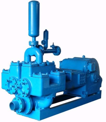
A mud pump is a reciprocating piston/plunger pump designed to circulate drilling fluid under high pressure (up to 7,500 psi (52,000 kPa)) down the drill string and back up the annulus. A duplex mud pump is an important part of the equipment used for oil well drilling.
Duplex mud pumps (two piston/plungers) have generally been replaced by the triplex pump, but are still common in developing countries. Two later developments are the hex pump with six vertical pistons/plungers, and various quintuplex’s with five horizontal piston/plungers. The advantages that Duplex mud pumps have over convention triplex pumps is a lower mud noise which assists with better Measurement while drilling and Logging while drilling decoding.
Use duplex mud pumps to make sure that the circulation of the mud being drilled or the supply of liquid reaches the bottom of the well from the mud cleaning system. Despite being older technology than the triplex mud pump, the duplex mud pumps can use either electricity or diesel, and maintenance is easy due to their binocular floating seals and safety valves.
A mud pump is composed of many parts including mud pump liner, mud pump piston, modules, hydraulic seat pullers, and other parts. Parts of a mud pump:housing itself
Duplex pumps are used to provide a secondary means of fuel transfer in the event of a failure of the primary pump. Each pump in a duplex set is sized to meet the full flow requirements of the system. Pump controllers can be set for any of the following common operating modes:Lead / Lag (Primary / Secondary): The lead (primary) pump is selected by the user and the lag (secondary pump operates when a failure of the primary pump is detected.
Alternating: Operates per Lead / Lag (Primary / Secondary) except that the operating pump and lead / lag status alternate on consecutive starts. A variation is to alternate the pumps based on the operating time (hour meter) of the lead pump.

The mud pumps market size is expected to grow at a significant rate during the forecast period. A mud pump is a large, high-pressure (up to 7500 psi), single-acting triplex reciprocating pump used to circulate mud in a well at a specific flow rate (between 100 and 1300 gallons per minute). Instead of a triplex reciprocating pump, a double-acting two-cylinder reciprocating pump is occasionally utilized as a mud pump. Typically, a rig operator keeps two or three mud pumps on hand, one of which is active and the others on standby in case of an emergency. Mud is gathered up with the use of mud pumps, which use suction to circulate the mud from the wellbore to the surface during the drilling process.
Increased demand for directional and horizontal drilling, higher pressure handling capabilities, and some new oil discoveries are the main drivers of this market"s growth. Mud pumps are specialized pumps that are used to transport and circulate drilling fluids and other related fluids in a variety of industries, including mining and onshore and offshore oil and gas. The global energy demand is boosting the market for mud pumps. However, high drilling costs, environmental concerns, and shifting government energy and power laws may stymie industry growth.
Innovation in technology is the key for further growth for example, MTeq uses Energy Recovery’s Pressure exchanger technology in the drilling industry, as the ultimate engineered solution to increase productivity and reduce operating costs in pumping process by rerouting rough fluids away from high-pressure pumps, which helps reduce the cost of maintenance for operators.
The major key player in global mud pumps market are Flowserve (U.S.), Grundfos (Denmark), Halliburton (U.S.), Sulzer (Switzerland), KSB Group (Germany), Ebara Corporation (Japan), Weir Group (U.K), and SRS Crisafulli, Inc (U.S.). Tsurumi Pump (Japan), Shijiazhuang Industrial Pump Factory Co. Ltd (China), Excellence Pump Industry Co.Ltd (China), Kirloskar Ebara Pumps Limited (India), Xylem Inc (U.S.), and Goulds Pumps (U.S.) are among others.
In the drilling business, MTeq uses Energy Recovery"s Pressure exchanger technology as the ultimate engineering solution to boost productivity and lower operating costs in the pumping process by rerouting abrasive fluids away from high-pressure pumps, which helps operators save money on maintenance. The latest trend reveals that regulatory agencies are persuading manufacturers and consumers to choose electric mud pumps over fuel engine mud pumps to reduce the environmental impact of fuel engine mud pumps.
The global mud pumps market is segmented on the basis of type (duplex pump, triplex pump, and others), component (fluid end and power end), application (oil & gas industry and building industry), and Region (North America, Europe, Asia Pacific, and Rest of the World).
Based on type, mud pumps can be segmented as duplex and triplex pumps. Triplex pumps are expected to progress because of the ~30.0% lesser weight than duplex pumps offering similar efficiency. The pump transfers the fluids with the help of mechanical movements.
Based on application, mud pumps market can be segmented as oil & gas industry and building industry. As oil and gas fields going mature, operators must drill wells with large offset, high laterals, widening their applicability by using mud motors, and high-pressure pumps. To fulfill the demand drilling companies increase their mud pumping installation capacity, with higher flexibility. For instance, LEWCO has developed W-3000 mud pump model for oil drilling, which can handle power up to 3000 HP.
Based on region, North America is predominant because of tight oil and shale gas sources, followed by Asia-Pacific due to the increased number of wells in the regions, especially in countries such as China and India due to the rapid urbanization and industrialization. Authorities in countries such as India, China are working on enhancing their production capacities for reducing the import bills, which ultimately help in the growth of mud pumps market.
This market is broadly driven by oil and gas industry as mud pumps are used to move massive amount of sludge and mud at the time of drilling. Countries such as China, Russia, Saudi Arabia, and the U.S. have the largest number of oil wells. The demand for mud pumps will increase with the number of oil wells, across the globe.

A properly serviced pulsation dampener is critical for your mud pumps’ efficiency, safety, and performance. Unfortunately, there aren’t many resources available to educate personnel on executing safe and effective servicing procedures. Please review the following steps with your personnel for safe pulsation dampener maintenance.

CONTENTSChapter 1 Basic Formulas P. 3 1. Pressure Gradient 2. Hydrostatic Pressure 3. Converting Pressure into Mud Weight 4. Specific Gravity 5. Equivalent Circulating Density 6. Maximum Allowable Mud Weight 7. Pump Output 8. Annular Velocity 9. Capacity Formula 10. Control Drilling 11. Buoyancy Factor 12. Hydrostatic Pressure Decrease POOH 12. Loss of Overbalance Due to Falling Mud Level 13. Formation Temperature 14. Hydraulic Horsepower 15. Drill Pipe/Drill Collar Calculations 16. Pump Pressure/ Pump Stroke 17. Relationship 18. Cost Per Foot om 19. Temperature Conversion Formulas
Chapter 2 Basic Calculations P. 25 1. Volumes and Strokes 2. Slug Calculations 3. Accumulator Capacity — Usable Volume Per Bottle 4. Bulk Density of Cuttings (Using Mud Balance) l.c 5. Drill String Design (Limitations) 6. Ton-Mile (TM) Calculations 7. Cementing Calculations 8. Weighted Cement Calculations 9. Calculations for the Number of Sacks of Cement Required 10. Calculations for the Number of Feet to Be Cemented oi
11. Setting a Balanced Cement Plug 12. Differential Hydrostatic Pressure Between Cement in the Annulus and Mud Inside the Casing 13. Hydraulicing Casing 14. Depth of a Washout 15. Lost Returns — Loss of Overbalance 16. Stuck Pipe Calculations 17. Calculations Required for Spotting Pills 18. Pressure Required to Break Circulation
Chapter 3 Drilling Fluids P. 63 1. Increase Mud Weight 2. Dilution 3. Mixing Fluids of Different Densities 4. Oil Based Mud Calculations 5. Solids Analysis 6. Solids Fractions 7. Dilution of Mud System 8. Displacement - Barrels of Water/Slurry Required 9. Evaluation of Hydrocyclone 10. Evaluation of Centrifuge
1. Pressure GradientPressure gradient, psi/ft, using mud weight, ppgpsi/ft = mud weight, ppg x 0.052 Example: 12.0 ppg fluidpsi/ft = 12.0 ppg x 0.052psi/ft = 0.624
Pressure gradient, psi/ft, using mud weight, lb/ft3psi/ft = mud weight, lb/ft3 x 0.006944 Example: 100 lb/ft3 fluidpsi/ft = 100 lb/ft3 x 0.006944psi/ft = 0.6944OR
psi/ft = mud weight, lb/ft3 ÷ 144 Example: 100 lb/ft3 fluidpsi/ft = 100 lb/ft3 ÷ 144psi/ft = 0.6944 omPressure gradient, psi/ft, using mud weight, specific gravity (SG)psi/ft = mud weight, SG x 0.433 Example: 1.0 SG fluidpsi/ft = 1.0 SG x 0.433 l.cpsi/ft = 0.433
Convert pressure gradient, psi/ft, to mud weight, lb/ft3lb/ft3 = pressure gradient, psi/ft ÷ 0.006944 Example: 0.6944 psi/ftlb/ft3 = 0.6944 psi/ft ÷ 0.006944lb/ft3 = 100
2. Hydrostatic Pressure (HP)Hydrostatic pressure using ppg and feet as the units of measureHP = mud weight, ppg x 0.052 x true vertical depth (TVD), ftExample: mud weight = 13.5 ppg true vertical depth = 12,000 ftHP = 13.5 ppg x 0.052 x 12,000 ftHP = 8424 psi
Hydrostatic pressure, psi, using pressure gradient, psi/ftHP = psi/ft x true vertical depth, ftExample: Pressure gradient = 0.624 psi/ft true vertical depth = 8500 ftHP = 0.624 psi/ft x 8500 ftHP = 5304 psi omHydrostatic pressure, psi, using mud weight, lb/ft3HP = mud weight, lb/ft3 x 0.006944 x TVD, ftExample: mud weight = 90 lb/ft3 true vertical depth = 7500 ftHP = 90 lb/ft3 x 0.006944 x 7500 ftHP = 4687 psi l.c
3. Converting Pressure into Mud WeightConvert pressure, psi, into mud weight, ppg using feet as the unit ofmeasuremud weight, ppg = pressure, psi ÷ 0.052 + TVD, ftExample: pressure = 2600 psi true vertical depth = 5000 ftmud, ppg = 2600 psi ÷ 0.052 ÷ 5000 ftmud = 10.0 ppg
Convert pressure, psi, into mud weight, ppg using meters as the unit ofmeasuremud weight, ppg = pressure, psi ÷ 0.052 ÷ TVD, m + 3.281Example: pressure = 3583 psi true vertical depth = 2000 metersmud wt, ppg = 3583 psi ÷ 0.052 ÷ 2000 m ÷ 3.281mud wt = 10.5 ppg
4. Specific Gravity (SG)Specific gravity using mud weight, ppgSG = mud weight, ppg + 8.33 Example: 15..0 ppg fluidSG = 15.0 ppg ÷ 8.33SG = 1.8 omSpecific gravity using pressure gradient, psi/ftSG = pressure gradient, psi/ft 0.433 Example: pressure gradient = 0.624 psi/ftSG = 0.624 psi/ft ÷ 0.433SG = 1.44 l.c
Convert specific gravity to mud weight, ppgmud weight, ppg = specific gravity x 8.33 Example: specific gravity = 1.80mud wt, ppg = 1.80 x 8.33mud wt = 15.0 ppg
Convert specific gravity to mud weight, lb/ft3lb/ft3 = specific gravity x 62.4 Example: specific gravity = 1.92lb/ft3 = 1.92 x 62.4lb/ft3 = 120
5. Equivalent Circulating Density (ECD), ppgECD, ppg = (annular pressure, loss, psi ) ÷ 0.052 ÷ TVD, ft + (mud weight, in use, ppg)Example: annular pressure loss = 200 psi true vertical depth = 10,000 ftECD, ppg = 200 psi ÷ 0.052 ÷ 10,000 ft + 9.6 ppgECD = 10.0 ppg
om6. Maximum Allowable Mud Weight from Leak-off Test Datappg = (Leak-off Pressure, psi ) ÷ 0.052 ÷ (Casing Shoe TVD, ft) + (mud weight, ppg)Example: leak-off test pressure = 1140 psi casing shoe TVD = 4000 ft Mud weight = 10.0 ppg l.cppg = 1140 psi ÷ 0.052 ÷ 4000 ft + 10.0 ppg ppg = 15.48 oi
7. Pump Output (P0)Triplex Pump Formula 1PO, bbl/stk = 0.000243 x (liner diameter, in.)2 X (stroke length, in.)Example: Determine the pump output, bbl/stk, at 100% efficiency for a 7-in, by 12-in, triplex pump:PO @ 100% = 0.000243 x 72 x 12PO @ 100% = 0.142884 bbl/stkAdjust the pump output for 95% efficiency: Decimal equivalent = 95 ÷ 100 = 0.95PO @ 95% = 0.142884 bbl/stk x 0.95PO @ 95% = 0.13574 bbl/stk
Formula 2PO, gpm = [3 (72 x 0.7854) S] 0.00411 x SPMwhere D = liner diameter, in. S = stroke length, in. SPM = strokes per minuteExample: Determine the pump output, gpm, for a 7-in, by 12-in, triplex pump at 80 strokes per minute:PO, gpm = [3 (72 x 0.7854) 12] 0.00411 x 80PO, gpm = 1385.4456 x 0.00411 x 80PO = 455.5 gpm
Duplex Pump Formula 1 0.000324 x (Liner Diameter, in.)2 x (stroke length, in.) = _________ bbl/stk-0.000162 x (Liner Diameter, in.)2 x (stroke length, in.) = _________ bbl/stk Pump output @ 100% eff = _________ bbl/stkExample: Determine the output, bbl/stk, of a 5-1/2 in, by 14-in, duplex pump at 100% om efficiency. Rod diameter = 2.0 in.: 0.000324 x 5.52 x 14 = 0.137214 bbl/stk-0.000162 x 2.02 x 14 = 0.009072 bbl/stk pump output 100% eff = 0.128142 bbl/stk
Example: Determine the output, bbl/stk, of a 5-1/2-in, by 14-in, duplex pump 100% efficiency. Rod diameter — 2.0 in.:PO @ 100% = 0.000162 x 14 x [2 (5.5) 2 -22 ]PO @ 100% = 0.000162 x 14 x 56.5PO @ 100% = 0.128142 bbl/stkAdjust pump output for 85% efficiency:PO @ 85% = 0.128142 bbl/stk x 0.85PO @ 85% = 0.10892 bbl/stk
8. Annular Velocity (AV)Annular velocity (AV), ft/minFormula 1AV = pump output, bbl/min ÷ annular capacity, bbl/ftExample: pump output = 12.6 bbl/min annular capacity = 0.126 1 bbl/ftAV = 12.6 bbl/min ÷ 0.1261 bbl/ftAV = 99.92 ft/mm
where Q = circulation rate, gpm, Dh = inside diameter of casing or hole size, in. Dp = outside diameter of pipe, tubing or collars, in. omExample: pump output = 530 gpm hole size = 12-1/4th. pipe OD = 4-1/2 in.AV = 24.5 x 530 12.252 — 452AV = 12,985 129.8125 l.cAV = 100 ft/mm
AV, ft/min = PO, bbl/min x 1029.4 Dh2 — Dp2Example: pump output = 12.6 bbl/min hole size = 12-1/4 in. pipe OD = 4-1/2 in.AV = 12.6 bbl/min x 1029.4 12.252 — 452AV = 12970.44 129.8125AV = 99.92 ft/mm
Example: pump output = 12.6 bbl/min hole size = 12-1/4 in. pipe OD = 4-1/2 in.AV = 17.16 x 12.6 bbl/min 12.252 — 452AV = 216.216 129.8125AV = 1.6656 ft/sec
Pump output, gpm, required for a desired annular velocity, ft/mmPump output, gpm = AV, ft/mm (Dh2 — DP2) 24 5where AV = desired annular velocity, ft/min Dh = inside diameter of casing or hole size, in. Dp = outside diameter of pipe, tubing or collars, in.Example: desired annular velocity = 120 ft/mm hole size = 12-1/4 in pipe OD = 4-1/2 in. omPO = 120 (12.252 — 452) 24.5PO = 120 x 129.8125 24.5PO = 15577.5 l.c 24.5PO = 635.8 gpm
SPM = annular velocity, ft/mm x annular capacity, bbl/ft pump output, bbl/stkExample. annular velocity = 120 ft/min annular capacity = 0.1261 bbl/ft Dh = 12-1/4 in. Dp = 4-1/2 in. pump output = 0.136 bbl/stkSPM = 120 ft/mm x 0.1261 bbl/ft 0.136 bbl/stkSPM = 15.132 0.136SPM = 111.3
10. Control Drilling l.cMaximum drilling rate (MDR), ft/hr, when drifting large diameter holes (14-3/4 in. and larger)MDR, ft/hr = 67 x (mud wt out, ppg — mud wt in, ppg) x (circulation rate, gpm) Dh2 oi
Example: Determine the MDR, ft/hr, necessary to keep the mud weight coming out at 9.7 ppg at the flow line:Data: Mud weight in = 9.0 ppg Circulation rate = 530 gpm Hole size = 17-1/2 in.MDR, ft/hr = 67 (9.7 — 9.0) 530 17.52MDR, ft/hr = 67 x 0.7 x 530 306.25MDR, ft/hr = 24,857 306.25MDR = 81.16 ft/hr
11. Buoyancy Factor (BF)Buoyancy factor using mud weight, ppgBF = 65.5 — mud weight, ppg 65.5Example: Determine the buoyancy factor for a 15.0 ppg fluid:BF = 65.5 — 15.0 65.5BF = 0.77099
Buoyancy factor using mud weight, lb/ft3BF = 489 — mud weight, lb/ft3 489Example: Determine the buoyancy factor for a 120 lb/ft3 fluid: omBF = 489 — 120 489BF = 0.7546 l.c12. Hydrostatic Pressure (HP) Decrease When POOHWhen pulling DRY pipe oi
Step 2HP psi decrease = barrels displaced x 0.052 x mud weight, ppg (casing capacity — pipe displacement) bbl/ft bbl/ftExample: Determine the hydrostatic pressure decrease when pulling DRY pipe out of the hole:Number of stands pulled = 5 Pipe displacement = 0.0075 bbl/ftAverage length per stand = 92 ft Casing capacity = 0.0773 bbl/ftMud weight = 11.5 ppg
Step 2HP, psi = barrels displaced x 0.052 x mud weight, ppg (casing capacity) — (Pipe disp., + pipe cap.,) l.c bbl/ft bbl/ft bbl/ftExample: Determine the hydrostatic pressure decrease when pulling WET pipe out of the hole:Number of stands pulled = 5 Pipe displacement = 0.0075 bbl/ft oi
13. Loss of Overbalance Due to Falling Mud LevelFeet of pipe pulled DRY to lose overbalanceFeet = overbalance, psi (casing cap. — pipe disp., bbl/ft) mud wt., ppg x 0.052 x pipe disp., bbl/ftExample: Determine the FEET of DRY pipe that must be pulled to lose the overbalance using the following data:Amount of overbalance = 150 psi Casing capacity = 0.0773 bbl/ftPipe displacement = 0.0075 bbl/ft Mud weight = 11.5 ppgFt = 150 psi (0.0773 — 0.0075) 11.5 ppg x 0.052 x 0.0075Ft = 10.47 0.004485Ft = 2334 omFeet of pipe pulled WET to lose overbalanceFeet = overbalance, psi x (casing cap. — pipe cap. — pipe disp.) mud wt., ppg x 0.052 x (pipe cap. : pipe disp., bbl/ft)
Example: Determine the feet of WET pipe that must be pulled to lose the overbalance l.c using the following data:Amount of overbalance = 150 psi Casing capacity = 0.0773 bbl/ftPipe capacity = 0.01776 bbl/ft Pipe displacement = 0.0075 bbl/ftMud weight = 11.5 ppg oi
17. Pump Pressure/Pump Stroke Relationship (Also Called the Roughneck’s Formula)Basic formulaNew circulating = present circulating X (new pump rate, spm : old pump rate, spm)2pressure, psi pressure, psiExample: Determine the new circulating pressure, psi using the following data:Present circulating pressure = 1800 psiOld pump rate = 60 spmNew pump rate = 30 spmNew circulating pressure, psi = 1800 psi x (30 spm : 60 spm)2New circulating pressure, psi = 1800 psi x 0.25New circulating pressure = 450 psi
omDetermination of exact factor in above equationThe above formula is an approximation because the factor “2” is a rounded-off number. Todetermine the exact factor, obtain two pressure readings at different pump rates and use thefollowing formula:Factor = log (pressure 1 : pressure 2) l.c log (pump rate 1 : pump rate 2)
Strokes to displace: drill string, Kelly to shale shaker and Strokes annulus,and total circulation from Kelly to shale shaker.Strokes = barrels ÷ pump output, bbl/stkExample: Determine volumes and strokes for the following:Drill pipe — 5.0 in. — 19.5 lb/f Inside diameter = 4.276 in. om Length = 9400 ftDrill collars — 8.0 in. OD Inside diameter = 3.0 in. Length = 600 ftCasing — 13-3/8 in. — 54.5 lb/f Inside diameter = 12.615 in. Setting depth = 4500 ftPump data — 7 in. by 12 in. triplex Efficiency = 95% Pump output = 0.136 @ 95%Hole size = 12-1/4 in.
Strokesa) Surface to bit strokes: Strokes = drill string volume, bbl ÷ pump output, bbl/stkSurface to bit strokes = 172.16 bbl ÷ 0.136 bbl/stk omSurface to bit strokes = 1266
b) Bit to surface (or bottoms-up strokes):Strokes = annular volume, bbl ÷ pump output, bbl/stkBit to surface strokes = 1231.84 bbl ÷ 0.136 bbl/stkBit to surface strokes = 9058 l.cc) Total strokes required to pump from the Kelly to the shale shaker:Strokes = drill string vol., bbl + annular vol., bbl ÷ pump output, bbl/stkTotal strokes = (172.16 + 1231.84) ÷ 0.136 oi
Step 2 Difference in pressure gradient between slug weight and mud weight:psi/ft = (slug wt, ppg — mud wt, ppg) x 0.052Step 3 Length of slug in drill pipe:Slug length, ft = pressure, psi ÷ difference in pressure gradient, psi/ft
Example: Determine the barrels of slug required for the following:Desired length of dry pipe (2 stands) = 184 ft Mud weight = 12.2 ppgDrill pipe capacity 4-1/2 in. — 16.6 lb/ft = 0.01422 bbl/ft Slug weight = 13.2 ppg
Example: Determine the weight of slug required for the following:Desired length of dry pipe (2 stands) = 184 ft Mud weight = 12.2 ppgDrill pipe capacity 4-1/2 in. — 16.6 lb/ft = 0.0 1422 bbl/ft Volume of slug = 25 bbl
Volume, height, and pressure gained because of slug:a) Volume gained in mud pits after slug is pumped, due to U-tubing:Vol., bbl = ft of dry pipe x drill pipe capacity, bbl/ft
b) Height, ft, that the slug would occupy in annulus:Height, ft = annulus vol., ft/bbl x slug vol., bbl omc) Hydrostatic pressure gained in annulus because of slug:HP, psi = height of slug in annulus, ft X difference in gradient, psi/ft between slug wt and mud wtExample: Feet of dry pipe (2 stands) = 184 ft Slug volume = 32.4 bbl Slug weight = 13.2 ppg Mud weight = 12.2 ppg Drill pipe capacity 4-1/2 in. 16.6 lb/ft = 0.01422 bbl/ft l.c Annulus volume (8-1/2 in. by 4-1/2 in.) = 19.8 ft/bbl
Accumulator Pre-charge PressureThe following is a method of measuring the average accumulator pre-charge pressure byoperating the unit with the charge pumps switched off:
4. Bulk Density of Cuttings (Using Mud Balance)Procedure: om1. Cuttings must be washed free of mud. In an oil mud, diesel oil can be used instead of water.2. Set mud balance at 8.33 ppg.3. Fill the mud balance with cuttings until a balance is obtained with the lid in place.4. Remove lid, fill cup with water (cuttings included), replace lid, and dry outside of mud balance.5. Move counterweight to obtain new balance. l.cThe specific gravity of the cuttings is calculated as follows:SG = 1 . 2 (O.l2 x Rw) oi
Example: Desired WOB while drilling = 50,000 lb om Safety factor = 15% Drill collar weight 8 in. OD—3 in. ID = 147 lb/ft Mud weight = 12.0 ppg
Example: Drill pipe (5.0 in.) = 21.87 lb/ft - Grade G Tensile strength = 554,000 lb BHA weight in air = 50,000 lb BHA length = 500 ft Desired overpull = 100,000 lb Mud weight = 13.5 ppg Safety factor = 10%a) Buoyancy factor:BF = 65.5 — 13.5 om 65.5BF = 0.7939
Round trip ton-miles (RTTM)RTTM = Wp x D x (Lp + D) ÷ (2 x D) (2 x Wb + Wc) 5280 x 2000where RTTM = round trip ton-miles Wp = buoyed weight of drill pipe, lb/ft D = depth of hole, ft Lp = length of one stand of drill pipe, (aye), ft Wb = weight of travelling block assembly, lb Wc = buoyed weight of drill collars in mud minus the buoyed weight of the same length of drill pipe, lb 2000 = number of pounds in one ton 5280 = number of feet in one mileExample: Round trip ton-milesMud weight = 9.6 ppg Average length of one stand = 60 ft (double)Drill pipe weight = 13.3 lb/ft Measured depth = 4000 ftDrill collar length = 300 ft Travelling block assembly = 15,000 lb omDrill collar weight = 83 lb/ft
1. How many sacks of LEAD cement will be required?2. How many sacks of TAIL cement will be required?3. How many barrels of mud will be required to bump the plug?4. How many strokes will be required to bump the top plug?
Data: Casing setting depth = 3000 ft Hole size = 17-1/2 in. Casing 54.5 lb/ft = 13-3/8 in. Casing ID = 12.615 in. Float collar (feet above shoe) = 44 ft Pump (5-1/2 in. by 14 in. duplex @ 90% eff) 0.112 bbl/stk
Step 4 Determine the barrels of mud required to bump the top plug:Casing capacity, bbl = (3000 ft — 44 ft) x 0.1545 bbl/ftCasing capacity = 456.7 bbl
Example: From the data listed below, determine the following:1. Height, ft, of the cement in the annulus2. Amount, ft3, of the cement in the casing3. Depth, ft, of the top of the cement in the annulus om4. Number of barrels of mud required to displace the cement5. Number of strokes required to displace the cement
Data: Casing setting depth = 3000 ft Hole size = 17-1/2 in. Casing — 54.5 lb/ft = 13-3/8 in. Casing ID = 12.615 in. Drill pipe (5.0 in. — 19.5 lb/ft) = 0.01776 bbl/ft l.c Pump (7 in. by 12 in. triplex @ 95% eff.) = 0.136 bbl/stk Cementing tool (number of feet above shoe) = 100 ftCementing program: NEAT cement = 500 sk Slurry yield = 1.15 ft3/sk Excess volume = 50% oi
Step 3 Determine the spacer volume (usually water), bbl, to be pumped behind the slurry to balance the plug:Spacer vol, bbl = annular capacity, ÷ excess x spacer vol ahead, x pipe or tubing capacity, ft/bbl bbl bbl/ftNOTE: If no excess is to be used, simply omit the excess step.
Example 1: A 300 ft plug is to be placed at a depth of 5000 ft. The open hole size is 8-1/2 in. and the drill pipe is 3-1/2 in. — 13.3 lb/ft; ID — 2.764 in. Ten barrels of water are to be pumped ahead of the slurry. Use a slurry yield of 1.15 ft3/sk. Use 25% as excess slurry volume:Determine the following:1. Number of sacks of cement required2. Volume of water to be pumped behind the slurry to balance the plug3. Plug length before the pipe is withdrawn4. Amount of mud required to spot the plug plus the spacer behind the plug
Step 3 Determine the spacer volume (water), bbl, to be pumped behind the slurry to balance the plug:Spacer vol, bbl = 17.1569 ft/bbl ÷ 1.25 x 10 bbl x 0.00742 bbl/ftSpacer vol = 1.018 bbl
12. Differential Hydrostatic Pressure Between Cement in the Annulus and Mud Inside the Casing1. Determine the hydrostatic pressure exerted by the cement and any mud remaining in the annulus.2. Determine the hydrostatic pressure exerted by the mud and cement remaining in the casing.3. Determine the differential pressure.Example: 9-5/8 in. casing — 43.5 lb/ft in 12-1/4 in. hole: Well depth = 8000 ft Cementing program: LEAD slurry 2000 ft = 13.8 lb/gal TAIL slurry 1000 ft = 15.8 lb/gal Mud weight = 10.0 lb/gal Float collar (No. of feet above shoe) = 44 ft
Determine the total hydrostatic pressure of cement and mud in the annulusa) Hydrostatic pressure of mud in annulus:HP, psi = 10.0 lb/gal x 0.052 x 5000 ftHP = 2600 psi
Determine the total pressure inside the casinga) Pressure exerted by the mud:HP, psi = 10.0 lb/gal x 0.052 x (8000 ft — 44 ft)HP = 4137 psi l.c
Determine the Upward Force (F), lb. This is the weight, total force, acting atthe bottom of the shoe omForce, lb = area, sq in. x differential pressure between cement and mud, psi
Check the forces with the new mud weighta) psi/ft = (cement wt, ppg — mud wt, ppg) x 0.052b) psi = difference in pressure gradients, psi/ft x casing length, ftc) Upward force, lb = pressure, psi x area, sq in.d) Difference in = upward force, lb — downward force, lb force, lb
Example: Casing size = 13 3/8 in. 54 lb/ft Cement weight = 15.8 ppg Mud weight = 8.8 ppg Buoyancy factor = 0.8656 Well depth = 164 ft (50 m)
d) Differential force, lb = downward force — upward force Differential force, lb = 7737 lb — 7668 lb Differential force = + 69 lb om14. Depth of a WashoutMethod 1 l.cPump soft line or other plugging material down the drill pipe and notice how many strokes arerequired before the pump pressure increases.
Example: Drill pipe = 3-1/2 in. 13.3 lb/ft Capacity = 0.00742 bbl/ft Pump output = 0.112 bbl/stk (5-1/2 in. by 14 in. duplex @ 90% efficiency)NOTE:A pressure increase was noticed after 360 strokes.Depth of washout, ft = 360 stk x 0.112 bbl/stk ÷ 0.00742 bbl/ftDepth of washout = 5434 ft
Method 2Pump some material that will go through the washout, up the annulus and over the shaleshaker. This material must be of the type that can be easily observed as it comes across theshaker. Examples: carbide, corn starch, glass beads, bright coloured paint, etc.Depth of = strokes x pump output, ÷ (drill pipe capacity, bbl/ft + annular capacity, bbl/ft)washout, ft required bbl/stk
Example: Drill pipe = 3-1/2 in. 13.3 lb/ft capacity = 0.00742 bbl/ft Pump output = 0.112 bbl/stk (5-1/2 in. x 14 in. duplex @ 90% efficiency) Annulus hole size = 8-1/2 in. Annulus capacity = 0.0583 bbl/ft (8-1/2 in. x 3-1/2 in.)NOTE: The material pumped down the drill pipe was noticed coming over the shaker after 2680 strokes.Drill pipe capacity plus annular capacity:
15. Lost Returns — Loss of OverbalanceNumber of feet of water in annulus omFeet = water added, bbl ÷ annular capacity, bbl/ftBottomhole (BHP) pressure reductionBHP decrease, psi = (mud wt, ppg — wt of water, ppg) x 0.052 x (ft of water added) l.cEquivalent mud weight at TDEMW, ppg = mud wt, ppg — (BHP decrease, psi ÷ 0.052 ÷ TVD, ft)
Determine the height, ft of unweighted spotting fluid that will balanceformation pressure in the annulus:a) Determine the difference in pressure gradient, psi/ft, between the mud weight and the spotting fluid:psi/ft = (mud wt, ppg — spotting fluid wt, ppg) x 0.052
b) Determine the height, ft, of unweighted spotting fluid that will balance formation pressure in the annulus: omHeight ft = amount of overbalance, psi ÷ difference in pressure gradient, psi/ftExample. Use the following data to determine the height, ft, of spotting fluid that will balance formation pressure in the annulus:Data: Mud weight = 11.2 ppg Weight of spotting fluid = 7.0 ppgAmount of overbalance = 225.0 psi l.ca) Difference in pressure gradient, psi/ft:psi/ft = (11.2 ppg — 7.0 ppg) x 0.052psi/ft = 0.2184 oi
Step 7 Determine strokes required to chase pill:Strokes = bbl required to ÷ pump output, + strokes required to chase pill bbl/stk displace surface system
Step 8 Total strokes required to spot the pill:Total strokes = strokes required to pump pill + strokes required to chase pillExample: Drill collars are differentially stuck. Use the following data to spot an oil based pill around the drill collars plus 200 ft (optional) above the collars. Leave 24 bbl in the drill string:
Data: Well depth = 10,000 ft Pump output = 0.117 bbl/stk Hole diameter = 8-1/2 in. Washout factor = 20% Drill pipe = 5.0 in. 19.5 lb/ft Drill collars = 6-1/2 in. OD x 2-1/2 in. ID capacity = 0.01776 bbl/ft capacity = 0.006 1 bbl/ft length = 9400 ft length = 600 ft
Step 7 Determine strokes required to chase pill:Strokes = 146.6 bbl ÷ 0.117 bbl/stk + 80 stkStrokes = 1333 omStep 8 Determine strokes required to spot the pill:Total strokes = 479 + 1333Total strokes = 1812 l.c18. Pressure Required to Break CirculationPressure required to overcome the mud’s gel strength inside the drill string oi
1. Increase Mud DensityMud weight, ppg, increase with barite (average specific gravity of barite - 4.2)Barite, sk/100 bbl = 1470 (W2 — W1) 35 — W2Example: Determine the number of sacks of barite required to increase the density of 100 bbl of 12.0 ppg (W1) mud to 14.0 ppg (W2):
Volume increase, bbl, due to mud weight increase with barite omVolume increase, per 100 bbl = 100 (W2 — W1) 35 — W2Example: Determine the volume increase when increasing the density from 12.0 ppg (W1) to 14.0 ppg (W2):Volume increase, per 100 bbl = 100 (14.0 — 12.0) l.c 35 — 14.0Volume increase, per 100 bbl = 200 21 oi
Starting volume, bbl, of original mud weight required to give apredetermined final volume of desired mud weight with bariteStarting volume, bbl = VF (35 — W2) 35 — W1Example: Determine the starting volume, bbl, of 12.0 ppg (W1) mud required to achieve 100 bbl (VF) of 14.0 ppg (W2) mud with barite:Starting volume, bbl = 100 (35 — 14.0) 35 — 12.0Starting volume, bbl = 2100 23Starting volume = 91.3 bbl
Mud weight increase with calcium carbonate (SG — 2.7)NOTE: The maximum practical mud weight attainable with calcium carbonate is 14.0 ppg.Sacks/ 100 bbl = 945(W2 — W1) 22.5 — W2Example: Determine the number of sacks of calcium carbonate/l00 bbl required to increase the density from 12.0 ppg (W1) to 13.0 ppg (W2):Sacks/ 100 bbl = 945 (13.0 — 12.0) 22.5 — 13.0Sacks/ 100 bbl = 945 9.5Sacks/ 100 bbl = 99.5
Volume increase, bbl, due to mud weight increase with calcium carbonateVolume increase, per 100 bbl =100 (W2 — W1) om 22.5 — W2
Starting volume, bbl, of original mud weight required to give apredetermined final volume of desired mud weight with calcium carbonateStarting volume, bbl = VF (22.5 — W2) 22.5 — W1Example: Determine the starting volume, bbl, of 12.0 ppg (W1) mud required to achieve 100 bbl (VF) of 13.0 ppg (W2) mud with calcium carbonate:Starting volume, bbl = 100 (22.5 — 13.0) 22.5 — 12.0Starting volume, bbl = 950 10.5
Mud weight increase with hematite (SG — 4.8)Hematite, sk/100 bbl = 1680 (W2 — W~) 40 — W2Example: Determine the hematite, sk/100 bbl, required to increase the density of 100 bbl of 12.0 ppg (W1) to 14.0 ppg (W2):Hematite, sk/100 bbl = 1680 (14.0 — 12.0) 40 — 14.0Hematite, sk/100 bbl = 3360 26Hematite = 129.2 sk/100 bbl
Volume increase, bbl, due to mud weight increase with hematiteVolume increase, per 100 bbl = l00 (W2 — W1) om 40 — W2Example: Determine the volume increase, bbl/100 bbl, when increasing the density from 12.0 ppg (W,) to 14.0 ppg (W2):Volume increase, per 100 bbl = 100 (14.0 — 12.0) 40 — 14.0 l.cVolume increase, per 100 bbl = 200 26Volume increase = 7.7 bbl per 100 bbl oi
Starting volume, bbl, of original mud weight required to give apredetermined final volume of desired mud weight with hematiteStarting volume, bbl = VF (40.0 — W2) 40 — W1Example: Determine the starting volume, bbl, of 12.0 ppg (W1) mud required to achieve 100 bbl (VF) of 14.0 ppg (W2) mud with hematite:Starting volume, bbl = 100 (40 — 14.0) 40 — 12.0Starting volume, bbl = 2600 28
2. DilutionMud weight reduction with waterWater, bbl = V1(W1 — W2) W2 — DwExample: Determine the number of barrels of water weighing 8.33 ppg (Dw) required to reduce 100 bbl (V1) of 14.0 ppg (W1) to 12.0 ppg (W2):Water, bbl = 100 (14.0 — 12.0) 12.0 — 8.33Water, bbl = 2000 3.67Water = 54.5 bbl
Mud weight reduction with diesel oil omDiesel, bbl = V1(W1 — W2) W2 — DwExample: Determine the number of barrels of diesel weighing 7.0 ppg (Dw) required to reduce 100 bbl (V1) of 14.0 ppg (W1) to 12.0 ppg (W2): l.cDiesel, bbl = 100 (14.0—12.0) 12.0 —7.0Diesel, bbl = 200 5.0 oi
3. Mixing Fluids of Different DensitiesFormula: (V1 D1) + (V2 D2) = VF DFwhere V1 = volume of fluid 1 (bbl, gal, etc.) D1 = density of fluid 1 (ppg,lb/ft3, etc.) V2 = volume of fluid 2 (bbl, gal, etc.) D2 = density of fluid 2 (ppg,lb/ft3, etc.) VF = volume of final fluid mix DF = density of final fluid mixExample 1: A limit is placed on the desired volume:Determine the volume of 11.0 ppg mud and 14.0 ppg mud required to build 300 bbl of11.5 ppg mud:Given: 400 bbl of 11.0 ppg mud on hand, and 400 bbl of 14.0 ppg mud on hand
Multiply Equation A by the density of the lowest mud weight (D1 = 11.0 ppg) and subtract theresult from Equation B: b) (11.0) (V1 ) + (14.0) (V2 ) = 3450— a) (11.0) (V1 ) + (11.0) (V2 ) = 3300 0 (3.0) (V2 ) = 150 3 V2 = 150 V2 = 150 3 V2 = 50Therefore: V2 = 50 bbl of 14.0 ppg mud om V1 + V2 = 300 bbl V1 = 300 — 50 V1 = 250 bbl of 11.0 ppg mudCheck: V1 = 50 bbl D1 = 14.0 ppg V2 = 150 bbl D2 = 11.0 ppg VF = 300 bbl DF = final density, ppg l.c(50) (14.0) + (250) (11.0) = 300 DF 700 + 2750 = 300 DF 3450 = 300 DF 3450 ÷ 300 = DF 11.5 ppg = DF oi
Example 2: No limit is placed on volume:Determine the density and volume when the two following muds are mixed together:Given: 400 bbl of 11.0 ppg mud, and 400 bbl of 14.0 ppg mud
Solution: let V1 = bbl of 11.0 ppg mud D1 = density of 11.0 ppg mud V2 = bbl of 14.0 ppg mud D2 = density of 14.0 ppg mud VF = final volume, bbl DF = final density, ppgFormula: (V1 D1) + (V2 D2) = VF DF(400) (l1.0) + (400) (l4.0) = 800 DF 4400 + 5600 = 800 DF 10,000 = 800 DF 10,000 ÷ 800 = DF 12.5 ppg = DF
4. Oil Based Mud CalculationsDensity of oil/water mixture being used(V1)(D,) + (V2)(D2) = (V~ + V2)DFExample: If the oil/water (o/w) ratio is 75/25 (75% oil, V1, and 25% water V2), the following material balance is set up:NOTE: The weight of diesel oil, D1 = 7.0 ppg The weight of water, D2 = 8.33 ppg
Starting volume of liquid (oil plus water) required to prepare a desiredvolume of mud l.cSV= 35 — W2 x DV 35 — W1where SV = starting volume, bbl W1 = initial density of oil/water mixture, ppg W2 = desired density, ppg Dv = desired volume, bbl oi
Obtain the percent-by-volume oil and percent-by-volume water from retort analysis or mudstill analysis. From the data obtained, the oil/water ratio is calculated as follows:
% by volume solids = 32The oil/water ratio is 75/25.Example 1: Increase the oil/water ratio to 80/20:In 100 bbl of this mud, there are 68 bbl of liquid (oil plus water). To increase the oil/waterratio, add oil. The total liquid volume will be increased by the volume of the oil added, but thewater volume will not change. The 17 bbl of water now in the mud represents 25% of theliquid volume, but it will represent only 20% of the new liquid volume.Therefore: let x = final liquid volumethen, 0.20x = 17 x = 17 : 0.20 x = 85 bblThe new liquid volume = 85 bbl
Barrels of oil to be added:Oil, bbl = new liquid vol — original liquid volOil, bbl = 85 — 68Oil = 17 bbl oil per 100 bbl of mudCheck the calculations. If the calculated amount of liquid is added, what will be the resultingoil/water ratio?% oil in liquid phase = original vol oil + new vol oil x 100 original liquid oil + new oil added% oil in liquid phase = 51+17 x 100 68 + 17% oil in liquid phase = 80% water would then be: 100 — 80 = 20Therefore: The new oil/water ratio would be 80/20.
Example 2: Change the oil/water ratio to 70/30: omAs in Example I, there are 68 bbl of liquid in 100 bbl of this mud. In this case, however, waterwill be added and the volume of oil will remain constant. The 51 bbl of oil represents 75% ofthe original liquid volume and 70% of the final volume:Therefore: let x = final liquid volumethen, 0.70x = 51 l.c x = 51 : 0.70 x = 73 bblBarrels of water to be added: oi
Water, bbl = new liquid vol — original liquid volWater, bbl = 73 — 68Water = 5 bbl of water per 100 bbl of mudCheck the calculations. If the calculated amount of water is added, what will be the resultingoil/water ratio?% water in liquid phase = 17 + 5 x 100 68 + 5% water in liquid = 30% oil in liquid phase = 100 — 30 = 70
5. Solids AnalysisBasic solids analysis calculationsNOTE: Steps 1 — 4 are performed on high salt content muds. For low chloride muds begin with Step 5.
Step 9 Bentonite determinationIf cation exchange capacity (CEC)/methytene blue test (MBT) of shale and mud are KNOWN:a) Bentonite, lb/bbl:Bentonite, lb/bbl = 1 : (1— (S : 65) x (M— 9 x (S : 65)) x % by vol LGSWhere S = CEC of shale M = CEC of mud
b) Bentonite, % by volume:Bent, % by vol = bentonite, lb/bbl ÷ 9.1If the cation exchange capacity (CEC)/methylene blue (MBT) of SHALE is UNKNOWN:a) Bentonite, % by volume = M — % by volume LGS 8where M = CEC of mudb) Bentonite, lb/bbl = bentonite, % by vol x 9.1
Example: Mud weight = 16.0 ppg CEC of mud = 30 lb/bbl Retort Analysis: om Chlorides = 73,000 ppm CEC of shale = 7 lb/bbl water = 57.0% by volume oil = 7.5% by volume solids = 35.5% by volume1. Percent by volume saltwater (SW) l.cSW = [(5.88 x 10⁻⁸)(73,000)1.2 + 1] x 57SW = [(5.88-8 x 685468.39) + 1] x 57SW = (0.0403055 + 1) x 57SW = 59.2974 percent by volume oi
Maximum recommended low gravity solids (LGS)LGS = ((SF : 100) — [0.3125 x ((MW : 8.33) — 1)]) x 200where SF = maximum recommended solids fractions, % by vol LGS = maximum recommended low gravity solids, % by vol MW = mud weight, ppgExample: Mud weight = 14.0 ppgDetermine: Maximum recommended solids, % by volume Low gravity solids fraction, % by volume Maximum recommended solids fractions (SF), % by volume:SF = (2.917 x 14.0) — 14.17SF = 40.838 — 14.17SF = 26.67 % by volume omLow gravity solids (LOS), % by volume:LGS = ((26.67 : 100) — [0.3125 x ((14.0 : 8.33) — 1)]) x 200 l.cLGS = 0.2667 — (0.3125 x 0.6807) x 200LGS = (0.2667 — 0.2127) x 200LGS = 0.054 x 200LGS = 10.8 % by volume oi
7. Dilution of Mud SystemVwm = Vm (Fct — Fcop) Fcop — Fcawhere Vwm = barrels of dilution water or mud required Vm = barrels of mud in circulating system Fct = percent low gravity solids in system Fcop = percent total optimum low gravity solids desired Fca = percent low gravity solids (bentonite and/or chemicals added)
8. Displacement — Barrels of Water/Slurry RequiredVwm = Vm (Fct — Fcop) om Fct — Fcawhere Vwm = barrels of mud to be jetted and water or slurry to be added to maintain constant circulating volume: l.cExample: 1000 bbl in mud system. Total LGS = 6%. Reduce solids to 4%:
9. Evaluation of HydrocycloneDetermine the mass of solids (for an unweighted mud) and the volume of water discarded byone cone of a hydrocyclone (desander or desilter):Volume fraction of solids (SF): SF = MW — 8.22 13.37Mass rate of solids (MS): MS = 19,530 x SF x V TVolume rate of water (WR) WR = 900 (1 — SF) V T
where SF = fraction percentage of solids MW = average density of discarded mud, ppg MS = mass rate of solids removed by one cone of a hydrocyclone, lb/hr V = volume of slurry sample collected, quarts T = time to collect slurry sample, seconds om WR = volume of water ejected by one cone of a hydrocyclone, gal/hr
f) Mass rate for API barite:QB = QM — QU — QP— QC — QD x 35 21.7 21.7 omwhere :MW = mud density into centrifuge, ppg PU = Underflow mud density, ppg l.cQM = mud volume into centrifuge, gal/m PW = dilution water density, ppgQW = dilution water volume, gal/mm PO = overflow mud density, ppgCD = additive content in mud, lb/bbl CC = clay content in mud, lb/bblQU = Underflow mud volume, gal/mm QC = mass rate of clay, lb/mmFU = fraction of old mud in Underflow QD = mass rate of additives, lb/mm oi
Example: Mud density into centrifuge (MW) = 16.2 ppg Mud volume into centrifuge (QM) = 16.5 gal/mm Dilution water density (PW) = 8.34 ppg Dilution water volume (QW) = 10.5 gal/mm Underfiow mud density (PU) = 23.4 ppg Overflow mud density (P0) = 9.3 ppg Clay content of mud (CC) = 22.5 lb/bbl Additive content of mud (CD) = 6 lb/bbl
Determine: Flow rate of Underflow Volume fraction of old mud in the Underflow Mass rate of clay into mixing pit Mass rate of additives into mixing pit Water flow rate into mixing pit Mass rate of API barite into mixing pit
a) Underfiow mud volume, gal/mm:QU = [ 16.5 x (16.2 — 9.3)] — [ 10.5 x (9.3 — 8.34) ] 23.4 — 9.3QU = 113.85 — 10.08 14.1QU = 7.4 gal/mm
b) Volume fraction of old mud in the Underflow:FU = 35 — 23.4 . 35 — 16.2 + [ (10.5 : 16.5) x (35 — 8.34)]FU = 11.6 . 18.8 + (0.63636 x 26.66)FU = 0.324%
ReferencesChenevert, Martin E., and Reuven Hollo, TI-59 Drilling Engineering Manual, PennWellPublishing Company, Tulsa, 1981.Crammer Jr., John L. Basic Drilling Engineering Manual, PennWell Publishing Company,Tulsa, 1982.Manual of Drilling Fluids Technology, Baroid Division, N.L. Petroleum Services, Houston,Texas, 1979.Mud Facts Engineering Handbook, Milchem Incorporated, Houston, Texas, 1984. om l.c oi
1. Kill Sheets and Related CalculationsNormal Kill SheetPre-recorded DataOriginal mud weight (OMW)___________________________ ppgMeasured depth (MD)_________________________________ ftKill rate pressure (KRP)____________ psi @ ______________ spmKill rate pressure (KRP)____________ psi @ ______________ spm
Data: Original mud weight Measured depth om = 9.6 ppg = 10,525 ft Kill rate pressure @ 50 spm = 1000 psi Kill rate pressure @ 30 spm = 600 psi Drill string: drill pipe 5.0 in. — 19.5 lb/ft capacity = 0.01776 bbl/ft l.c HWDP 5.0 in. 49.3 lb/ft capacity = 0.00883 bbl/ft length = 240 ft drill collars 8.0 in. OD — 3.0 in. ID capacity = 0.0087 bbl/ft oi
length = 360 ft Annulus: hole size = 12 1/4 in. drill collar/open hole capacity = 0.0836 bbl/ft drill pipe/open hole capacity = 0.1215 bbl/ft drill pipe/casing capacity = 0.1303 bbl/ft Mud pump (7 in. x 12 in. triplex @ 95% eff.) = 0.136 bbl/stk Leak-off test with 9,0 ppg mud = 1130 psi Casing setting depth = 4000 ft Shut-in drill pipe pressure = 480 psi Shut-in casing pressure = 600 psi Pit volume gain = 35 bbl True vertical depth = 10,000 ft
Kill weight mud (KWM) 480 psi ÷ 0.052 ÷ 10,000 ft + 9.6 ppg = 10.5 ppgInitial circulating pressure (ICP) 480 psi + 1000 psi = 1480 psiFinal circulating pressure (FCP) 10.5 ppg x 1000 psi ÷ 9.6 ppg = 1094 psi
Whenever a kick is taken in a highly deviated well, the circulating pressure can beexcessive when the kill weight mud gets to the kick-off point (KOP). If the pressure isexcessive, the pressure schedule should be divided into two sections: 1) from surface to KOP,and 2) from KOP to TD. The following calculations are used:
Determine strokes from KOP to TD:Strokes = drill string capacity, bbl/ft x measured depth to TD, ft x pump output, bbl/stkKill weight mud: KWM = SIDPP ÷ 0.052 ÷ TVD + OMWInitial circulating pressure: ICP = SIDPP + KRPFinal circulating pressure: FCP KWM x KRP ÷ 0MWHydrostatic pressure increase from surface to KOP:psi = (KWM - OMW) x 0.052 x TVD @ KOP
Example: Original mud weight (OMW) = 9.6 ppg l.c Measured depth (MD) = 15,000 ft Measured depth @ KOP = 5000 ft True vertical depth @ KOP = 5000 ft Kill rate pressure (KRP) @ 30 spm = 600 psi Pump output = 0.136 bbl/stk oi
Step 2 Assuming 100% of the mud is blown out of the hole, determine the hydrostatic pressure in the wellbore:Note: 70% to 80% of mud being blown out is sometimes used instead of l00%.HPgas = gas gradient, psi/ft x total depth, ft
Example: Proposed total depth = 12,000 ft Maximum mud weight to be used in drilling well = 12.0 ppg Safety factor = 4.0 ppg Gas gradient = 0.12 psi/ft
Determine the diverter line inside diameter that will equal the area between the casing and drillpipe:Diverter line ID, in. = sq. root (12.5152 — 5.02)Diverter line ID = 11.47 in. omFormation Pressure TestsTwo methods of testing: • Equivalent mud weight test • Leak-off testPrecautions to be undertaken before testing: l.c1. Circulate and condition the mud to ensure the mud weight is consistent throughout the system.2. Change the pressure gauge (if possible) to a smaller increment gauge so a more accurate measure can be determined. oi
3. Shut-in the well.4. Begin pumping at a very slow rate — 1/4 to 1/2 bbl/min.5. Monitor pressure, time, and barrels pumped.6. Some operators may have different procedures in running this test, others may include: a. Increasing the pressure by 100 psi increments, waiting for a few minutes, then increasing by another 100 psi, and so on, until either the equivalent mud weight is achieved or until Leak-off is achieved. b. Some operators prefer not pumping against a closed system. They prefer to circulate through the choke and increase back pressure by slowly closing the choke. In this method, the annular pressure loss should be calculated and added to the test pressure results.
1) This test is used primarily on development wells where the maximum mud weight that will be used to drill the next interval is known.2) Determine the equivalent test mud weight, ppg, Two methods are normally used.
Method 2: Subtract a value from the estimated fracture gradient for the depth of the casing shoe. omEquivalent test mud weight = (estimated fracture gradient, ppg ) — (safety factor)
Testing to leak-off test:1) This test is used primarily on wildcat or exploratory wells or where the actual fracture is not known.2) Determine the estimated fracture gradient from a “Fracture Gradient Chart.”3) Determine the estimated leak-off pressure.Estimated leak-off pressure = (estimated fracture — mud wt ) x 0.052 x (casing shoe) (gradient in use, ppg) ( TVD, ft )
Max allowable = (leak off pressure, psi) ÷ 0.052 ÷ (casing shoe) + (mud wt in use, ppg)mud weight, ppg ( TVD, ft )
Leak-off pressure = 1040 psiCasing shoe TVD = 4000 ftMud weight in use = 10.0 ppg omMax allowable mud weight, ppg = 1040 + 0.052 -~- 4000 + 10.0Max allowable mud weight, ppg = 15.0 ppg
Maximum Allowable Shut-in Casing Pressure (MASLCP)also called maximum allowable shut-in annular pressure (MASP): l.cMASICP = (maximum allowable — mud wt in use, ppg) x 0.052 x (casing shoe TVD, ft) (mud wt, ppg )Example: Determine the maximum allowable shut-in casing pressure using the following data: oi
Maximum allowable mud weight = 15.0 ppgMud weight in use = 12.2 ppgCasing shoe TVD = 4000 ftMASICP = (15.0 — 12.2) x 0.052 x 4000 ftMASICP = 582 psi
Kick Tolerance Factor (KTF)KTF = Casing shoe TVD, ft) x (maximum allowable mud wt, ppg — mud wt in use, ppg) well depthExample: Determine the kick tolerance factor (KTF) using the following data:Mud weight in use = 10.0 ppgCasing shoe TVD = 4000 ftWell depth TVD = 10,000 ftMaximum allowable mud weight (from leak-off test data) = 14.2 ppg
Maximum Formation Pressure (FP) That Can be Controlled WhenShutting-in a Well omMaximum FP, psi = (kick tolerance factor, ppg + mud wt in use, ppg) x 0.052 x TYD, ft
Data: Kick tolerance factor = 1.68 ppg Mud weight = 10.0 ppg True vertical depth = 10,000 ft l.cMaximum FP, psi = (1.68 ppg + 10.0 ppg) x 0.052 x 10,000 ftMaximum FP = 6074 psi oi
Data: Maximum allowable shut-in casing pressure = 874 psi Mud gradient (10.0 ppg x 0.052) = 0.52 psi/ft Gradient of influx = 0.12 psi/ft
where MASICP = maximum allowable shut-in casing (annulus) pressure, psi PL = leak-off pressure, psi D = true vertical depth to casing shoe, ft Mud wt2 = new mud wt, ppg Mud wt1 = original mud wt, ppg
Example: Leak-off pressure at casing setting depth (TVD) of 4000 ft was 1040 psi with 10.0 ppg in use. Determine the maximum allowable shut-in casing pressure with a mud weight of 12.5 ppg:
3. Kick AnalysisFormation Pressure (FP) With the Well Shut-in on a KickFP, psi = SIDPP, psi + (mud wt, ppg x 0.052 x TVD, ft)
Example: Determine the formation pressure using the following data:Shut-in drill pipe pressure = 500 psi Mud weight in drill pipe = 9.6 ppgTrue vertical depth = 10,000 ft
Bottom hole Pressure (BHP) With the Well Shut-in on a KickBHP, psi = SIDPP, psi + (mud wt, ppg x 0.052 x TVD, ft) omExample: Determine the bottom hole pressure (BHP) with the well shut-in on a kick:
Shut-in drill pipe pressure = 500 psi Mud weight in drill pipe = 9.6 ppgTrue vertical depth = 10,000 ft l.cBHP, psi = 500 psi + (9.6 ppg x 0.052 x 10,000 ft)BHP, psi = 500 psi + 4992 psiBHP = 5492 psi oi
SIDPP, psi = formation pressure, psi — (mud wt, ppg x 0.052 x TVD, ft)Example: Determine the shut-in drill pipe pressure


 8613371530291