
overshot fishing tool free sample
[0001] This invention relates to overshot fishing tools and relates more particularly but not exclusively to overshots for fishing coil tubing that is trapped down oil or gas wells.
[0003] A variety of through-tubing workover tools have been developed over the last few years which are marketed by various coil tubing operators and service companies.
[0005] On occasion the coil tubing workstring may become stuck due to unknown circumstances within the wellbore. Several tools are available to run on coil tubing with the original workstring to permit a controlled separation of the coil from the BHA (bottom-hole assembly).
[0006] However, in certain instances the coil tubing may be parted accidentally due to operator error. This typically results in the need for what is commonly known as a "fishing operation" to retrieve the broken tubing from the well.
[0007] The purpose of the fishing operation is to locate, latch, and retrieve the stuck or severed piece of coil tubing which has been left in the wellbore. There are various tools available from a range of service companies which can be selected and attached to the bottom of a fishing string.
[0008] One very important feature of a fishing tool is the method of catch and release of the retrieving mechanism. Almost every application depends greatly on the condition in which the top of the coil has been left.
[0010] This would be considerably simpler to engage with an overshot type tool as they depend on the fish being of a reasonably undistorted condition, both dimensionally and circumferentially.
[0011] In most cases coil tubing fishing tools have latching mechanisms which are designed to catch a nominal size tubing. Most are energised by upwards pull against tapered surfaces. However, such tools are designed for a nominal minimum catch size. Coil tubing, being very ductile and relatively thin walled, is quite easy to collapse. Therefore if by the time the minimum catch size has been reached on the grapple, the fish or coil tubing has not come free, the overshot or fishing tool may slip off prematurely.
[0012] As used in the specification and the accompanying claims, the term "thin-wall tubing" refers to tubing which has a wall thickness significantly less than the wall thickness of strings, pipes, casings, and the like, which are sufficiently thick-walled as to substantially withstand radial collapsing loads applied thereto by the slip of a typical prior-art overshot fishing tool. By way of contrast, thin-wall tubing is liable to suffer a radial collapse when subjected to the radial gripping force applied thereto by the slip of a typical prior-art overshot fishing tool upon an overpull being applied in an attempt to free stuck thin-wall tubing. The term "thin-wall tubing" particularly but not exclusively includes coil tubing as employed for through-tubing workover programmes on oil or gas wells.
[0013] It is therefore an object of the invention to provide an overshot fishing tool for fishing thin-wall tubing, and which obviates or mitigates the disadvantages of prior-art overshot fishing tools when applied to fishing thin-wall tubing.
[0014] According to a first aspect of the present invention there is provided an overshot fishing tool for use on thin-wall tubing extending longitudinally through said tool, said overshot fishing tool comprising at least one slip radially actuable by a longitudinal pull on said tool to apply a radially inwardly directed grip on thin-wall tubing in a longitudinally concentrated region thereof, said slip being such that said radially inwardly directed grip is maintained on said longitudinally concentrated region of the thin-wall tubing as said region circumferentially contracts by necking of the thin-wall tubing while said longitudinal pull exceeds the longitudinal yield level of said thin-wall tubing in said longitudinally concentrated region thereof, until said thin-wall tubing longitudinally parts at said region unless said longitudinal pull previously exceeds a longitudinal force longitudinally restraining longitudinal movement of the thin-wall tubing.
[0015] Said slip preferably comprises a circumferentially distributed array of radially inwardly moveable and radially inwardly directed jaws each shaped for line contact with the thin-wall tubing along a common circumference thereof. Said slip is preferably formed by a cylindriform array of a plurality of fingers longitudinally extending from a common circumferentially extending annulus, said fingers being mutually divided by longitudinally extending slots and said jaws being formed adjacent the free ends of said fingers, one said slot preferably extending through said annulus. The free ends of said fingers are preferably externally tapered away from said common annulus to form a generally conical external surface, and said tool preferably also comprises a substantially matchingly conical internal surface such that relative longitudinal movement of said surfaces produces a wedging action that causes said slip to apply said radially inwardly directed grip. Said conical internal surface is preferably formed on a slip bowl mounted inside said tool and operatively associated with said slip.
[0016] Said tool preferably comprises two such slips and slip bowls longitudinally spaced along the longitudinal axis of said tool with one said slip being the upper slip and having its jaws dimensioned to grip the thin-wall tubing in a primary grip prior to a secondary grip applied to the thin-wall tubing by the jaws of the other said slip, the slip bowl operatively associated with said upper slip being mounted inside said tool for limited longitudinal movement relative to said tool such that upon said primary grip being applied to the thin-wall tubing, said slip bowl undergoes longitudinal movement to engage the other said slip to drive the other said slip against the slip bowl operatively associated therewith to cause the other said slip to apply said secondary grip to the thin-wall tubing.
[0017] According to a second aspect of the present invention there is provided a fishing arrangement for fishing thin-wall tubing, said fishing arrangement comprising an overshot fishing tool according to the first aspect of the present invention, in combination with a hollow fishing string having a through bore with an internal diameter greater than the external diameter of thin-wall tubing to be fished by said arrangement, said through bore having an internal length at least equal to the length of thin-wall tubing to be swallowed thereby to the point at which the thin-wall tubing is to be gripped by said tool and potentially parted thereby.
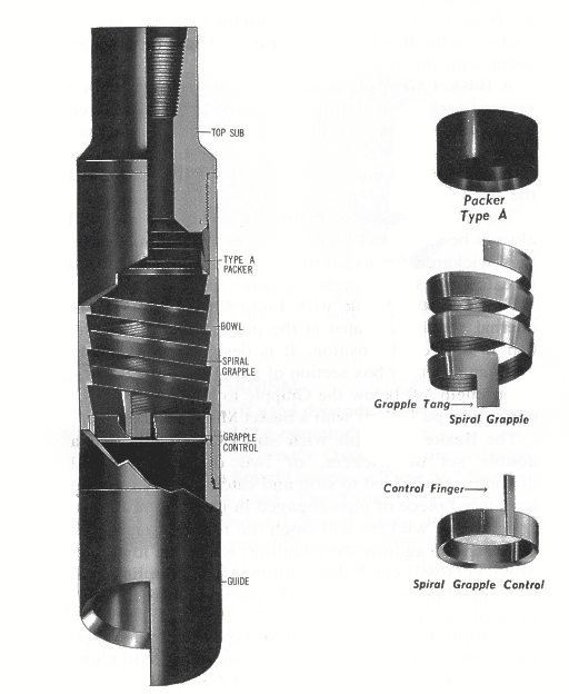
[0019] Referring first to Fig. 1, the first embodiment of the present invention is an overshot twin-slip fishing tool 10 having an upper slip assembly 12 and a lower slip assembly 14. The tool 10 is generally cylindrical, with a main hollow casing section 16 and an upper casing section 18 secured to the main casing section 16 by means of a screw-thread connection 20. A screw-thread connection 22 at the lower end of the main casing section 16 and a screw-thread connection 24 at the upper end of the upper casing section 18 enable the tool 10 to be screw-threadedly coupled into a hollow fishing string during use of the tool 10.
[0022] The lower slip assembly 14 similarly comprises a slip 46 and a slip bowl 48, the lower slip 46 being substantially identical to the upper slip 26, and the lower slip bowl 48 being substantially identical to the upper slip bowl 44, save that the lower slip bowl 48 is mounted within the main casing section 16 to be static therein during use of the tool 10.
[0026] In Fig. 3, the detail is a diametral sectional view of the tip of the slip jaw 34. Not directly visible in Fig. 3 (but see Fig. 1) is the formation of the serrations 36 as a left-hand wicker thread to facilitate rotational removal of fish after use of the tool 10. This structural feature is the same on both of the slips 26 and 46.
[0027] The function of the continuous coil tubing slip-type overshot fishing tool 10 of the present invention is to swallow the coil tubing continuously up through the bore of its casing sections 16 and 18. A suitably sized workstring (fishing string) will be run above the overshot fishing tool 10 to accommodate the coil tubing fish being swallowed. Once swallowed to a sufficient extent, an upward pull of the workstring will then engage the slips 26 and 46 on to the outside diameter of the coil tubing securing it firmly.
[0028] The slips 26 and 46 are manufactured with an internally tapered wicker thread, the point 36 of which initially concentrates a radial crushing load on the circumference of the coil tubing fish to cause necking (circumference reduction) of the coil tubing. The wicker profile is case hardened to bite in to the coil tubing. Once necking has progressed to the point at which the coil tubing fish is parted, the coil tubing may then be pulled from the well. The slips have shown in practice to be capable of carrying up to 80% of the yield strength of the coil tubing as necking has been apparent on tests conducted. Once yielding has occurred then an overpull applied through the fishing string will result in a tensile failure of the coil tubing directly underneath the lower slip teeth. This controlled overpull allows the operator to govern his overpull at his own discretion during the fishing and retrieval operation.
[0029] It is also possible to use the slip-type coil tubing overshot as a latch and retrieve overshot in instances where the coil tubing is not stuck. The slip-type overshot fishing tool 10, because of its design, may be run on a stronger and suitably sized coil tubing fishing string. This gives the capacity to pull and retrieve the coil tubing, if free, or the capacity to latch and break, if the coil tubing is permanently stuck.
[0031] One other important point is, that should circulation be required through the fish, then a packoff sub may be run in conjunction with the overshot fishing tool 10 to enable latch and circulation through the complete workstring.
[0032] On retrieval, the overshot fishing tool 10 leaves the top of the coil tubing in good round clean condition for relatching, if necessary. The slips 26 and 46 in the coil tubing slip-type overshot fishing tool 10 can accommodate up to plus 20% out-of-round fish or flattened fish during initial engagement.
[0036] This controlled loading mechanism allows both slips 26 and 46 to carry longitudinal fishing load. However, it is recognised that the coil tubing immediately below the lower slips 46 is subjected to the higher tensile load, therefore inducing the break in the coil tubing directly below the teeth on the lower slip 46.
[0037] Most prior art overshots have a catch and release type mechanism which requires axial or rotational movement to function. By way of contrast, the overshot fishing tool 10 of the present invention is suitable for coil tubing or other thin-wall tubing fish because the tool 10 concentrates a high radial load on a longitudinally highly localised region of the thin-wall tubing (effectively on a single circumferential line) at the point 36 where the slip jaws 34 grapple the thin-wall tubing, which ensures continued engagement even as the thin-wall tubing collapses radially inwards. The slips 26 and 46 also have an allowable radially inward jaw contraction far exceeding the equivalent maximum contraction on conventional overshots. This ensures continued slip grip until necking has progressed to the point of parting the thin-wall tubing. Prior art slips distribute their circumferential grip over a much greater axial length of the fish, as they are designed to do to avoid excessive radial load concentration. The prior art slips are also designed to have a much greater minimum diameter at which radial grip is maintained, such that when used on thin-wall tubing, such tubing will collapse to the point at which grip is lost, before necking progresses to the extent that the thin-wall tubing is parted.
[0038] Prior art fishing tools which maintain grip on tubing without load concentration may be able to pull the tubing free by breaking it by means of an overpull, but the position of the break will not be controlled and could occur anywhere, being determined only by the overpull and not by necking at a predetermined position on the tubing.
[0039] Thus the overshot fishing tool 10 of the present invention is ideal for fishing coil tubing and other thin-wall tubing, as it is designed to concentrate loading in a manner parting the tubing, and to maintain such grip despite the relatively large diameter reduction involved. If the tubing fish pulls free before being parted by necking, the result is equally satisfactory in terms of removing the fish from the borehole.
[0040] Fig. 4 depicts, in a highly schematic manner, a second embodiment 100 of overshot fishing tool in accordance with the invention, and its effect on a coil tubing fish 102. The second embodiment differs from the first embodiment (shown in Fig. 1 and detailed in Figs. 2 and 3) in that the second embodiment employs a single slip 104 (schematically depicted in Fig. 4 by a single diametral longitudinal cross-section). The slip 104 is formed to the same design as the slip 26 detailed in Fig. 2, and is co-operatively associated with an internally tapered slip bowl (omitted from Fig. 4) of the same design as the slip bowl 44 detailed in Fig. 2.
[0041] Fig. 4 schematically depicts the slip 104 having applied a radially inwardly directed and highly concentrated line load on the tubing 102 to an extent that the tubing 102 has necked and ultimately parted, so enabling fishing of coil tubing (or other thin-wall tubing) by controlled parting of the tubing at a predetermined location (the point of application of the single-slip overshot fishing tool 100). The longitudinal lift applied to the tool 100 and hence through the slip bowl to the slip 104 to contract the slip 104 causing necking and ultimate parting of the tubing 102, lifts the parted tubing 102 to remove it from the borehole.

It is common for objects, such as a segment of a pipe, to become stuck or forcibly lodged within a wellbore. In order for these objects to be removed from the wellbore, various fishing tools have been developed for the purpose of latching onto and retrieving the object, referred to in the industry as the “fish,” from the wellbore. One type of fishing tool is known as an overshot fishing tool because the tool is disposed over at least a portion of the object, or fish, disposed within the bore of the well. Such overshot fishing tools are generally known in the art. Other types of fishing tools that function by gripping the lumen of the fish, e.g., the inner diameter of a segment of pipe of the fish. Regardless of type of fishing tool, after the fish is gripped by the fishing tool, the fishing tool and the fish are transported to the surface of the well.
Broadly, the fishing tools disclosed herein comprise a tubular member having a fishing profile disposed within or secured to the inner wall surface of the tubular member. The fishing profile is shaped to allow a portion of the fish to move past the fishing profile so that the fishing profile is disposed below the portion of the fish. The tubular member can then be actuated, such as through rotation, to align the portion of the fish with a shoulder of the fishing profile. Upward movement of the tool engages the shoulder with the portion of the fish. Continued upward movement of the tool facilitates retrieval of the fish from the wellbore.
In the event that it is desired to release the fish from the fishing tool, the tubular member can be actuated a second time, such as through rotation, to move the shoulder of the fishing profile out of alignment with the portion of the fish. The tubular member can then be moved upward causing the portion of the fish to move past the fishing profile causing the fishing tool to move off the fish.
In one particular embodiment, the fishing profile comprises two shoulders disposed opposite each other along the inner wall surface of the tubular member with pathways disposed between the ends of the two shoulders. In other particular embodiments, the upper ends of the shoulders comprise a vertical stop member for engaging the fish during rotation of the tubular member. Thus, the vertical stop member provides the function of indicating when the fish is out of alignment with the shoulders so that the fishing tool can be moved off the fish. In still other embodiments, the lower ends of the shoulders comprise guides to facilitate aligning a portion of the fish with at least one of the pathways.
Broadly, the invention is directed to a fishing tool and in particular to a fishing tool which is a type of overshot tool. The fishing tool comprises profiled surfaces disposed on the inner wall surface of a tubular member. The profiled surfaces may be machined directly into the inner wall surface of the tubular member, or as discussed in greater detail below, one or more inserts may be separated formed and then secured to the inner wall surface of the tubular member.
Whether directly machined into the inner wall surface of the tubular member or formed as an insert that is then secured to the inner wall surface of the tubular member, the shape of the profiled surfaces (or inserts) facilitate catching a “fish” or object within the wellbore so that the fish can be removed from the wellbore. The profiled surfaces or inserts are disposed along the inner wall surface of the tubular member to provide pathways between each of the profiled surfaces or inserts. In one embodiment, each profiled surface or insert comprises a fishing or catch profile disposed toward an upper end, a guide disposed toward a lower end, and a release indicator member or stop member that is an extension along one side of the profiled surface or insert. The guide facilitates placement of the “fish” within the space or pathway between the two or more profiled surfaces or inserts and the catch profile receives and secures the “fish” to the profiled surface or insert. The release indicator member provides a signal to an operator at the surface of the wellbore when the fishing tool has released the “fish.” As will be understood by persons in the art, the fishing tools disclosed herein permit operation using mechanical input and do not require pumping, fluid flow, or pressure. However, in certain embodiments, pumping, fluid flow, or pressure also can be included to actuate the fishing tools disclosed herein.
In one particular embodiment, the fishing tools disclosed herein permit the fishing tool to remove pipe with flared, “egged,” or oblong fish profiles from a wellbore in one trip without the need to dress-off the fish top using traditional milling methods. In one operation of these fishing tools, drill pipe that has been sheared-off after activation of blowout preventer shear rams can be “fished” out of the wellbore. In addition, the fishing tools described herein also can be used to fish any downhole equipment that has a flared fish profile or other fish profile that can be engaged with the fishing or catch profile. As used herein, a flared fish profile is any geometry that is uniform along the axial direction but changes on top by having a wider dimension in one radial direction and a narrower dimension in another radial direction.
Referring now to Figures, in one particular embodiment, fishing tool 10 comprises tubular member 20 having upper end 21, lower end 22, outer wall surface 24, inner wall surface 26, and bore 28. Attachment members such as threads (not shown) can be disposed along inner wall surface 24 adjacent to upper end 21 and along outer wall surface 26 adjacent to lower end 22 to facilitate securing fishing tool 10 to a work string (not shown). In the embodiment discussed with respect to FIGS. 1-7, two inserts 60, 70 are secured to inner wall surface 26.
In the embodiments shown in FIGS. 1-3, inserts 60, 70 are identical to each other and are disposed relative to each other to provide pathways 80. As shown in the embodiments of FIGS. 1-3, inserts 60, 70 comprise arcuate bodies comprising upper ends 61, 71, lower ends 62, 72 having guides 64, 74 disposed respectively thereon, first sides 63, 73, second sides 65, 75, inner wall surfaces 69, 79, outer wall surfaces 94, 98, and fishing or catch profiles 66, 76. Guides 64, 74 facilitate orientating fishing tool 10 over an object or fish disposed in the wellbore by guiding inserts 60, 70 around the fish until fishing tool 10 can be positioned over the fish. As shown in the embodiment of FIGS. 1-3, guide 64 comprises intersecting wall surfaces 51, 53 that intersect with one another at point 55. Similarly, in the embodiment of FIGS. 1-3, guide 74 comprises intersecting wall surfaces 52, 54 that intersect with one another at point 56.
In the embodiment of FIGS. 1-3, catch profiles 66, 76 comprise shoulders each having a concave shape. In the embodiments of FIGS. 1-3, the concave shape comprises a V-shape with a “flat” valley 67, 77. The V-shape may provide an angle in the range from about 60 degrees to about 90 degrees. As discussed in greater detail below, fishing or catch profiles 66, 76 facilitate engagement with a fish disposed in the wellbore so that the fish can be moved up and, if desired, out of the wellbore.
Also in the embodiments shown in FIGS. 1-3, inserts 60, 70 include stop members or release indicator elements 68, 78. As shown in the embodiments of FIGS. 1-3, stop members or release indicator elements 68, 78 comprise vertical shaft members disposed along one side of inserts 60, 70. As discussed in greater detail below, release indicator elements 68, 78 facilitate notification to the operator of fishing tool 10 that fishing tool 10 has been orientated with respect to the fish such that fishing tool 10 can be moved off of the fish.
In one specific embodiment, inserts 60, 70 comprise the shapes and dimensions shown in FIGS. 3B, 3C, and 3E relating to inserts 60, 70, sides 63, 65, 73, 75, fishing profiles 66, 76, guides 64, 74, and release indicator elements 68, 78. In particular, inserts 60, 70 each comprise height 81, side height 82, guide height 83, release indicator element height 84, release indicator element width 85 (FIG. 3E), fishing profile width 86, and fishing profile valley width 87. Guides 64, 74 also comprise guide lower end thickness 88, and guide lower end profile angle 89 (both shown in FIG. 3C). In addition, pathway 80 comprises pathway width 90 (FIGS. 3C and 3E).
Height 81 can be in the range from approximately 16 inches to approximately 24 inches; side height 82 can be in the range from zero inches to approximately 12 inches; guide height 83 can be in the range from approximately 4 inches to approximately 6 inches; release indicator element height 84 can be in the range from approximately 4 inches to approximately 8 inches; release indicator element width 85 can be in the range from approximately 1.0 inch to approximately 1.5 inches; fishing profile width 86 can be in the range from approximately 4 inches to approximately 6 inches; fishing profile valley width 87 can be in the range from approximately 0.15 inches to approximately 0.25 inches; guide lower end thickness 88 can be in the range from approximately 0.5 inches to approximately 1.0 inch; guide lower end profile angle can be in the range from approximately 15 degrees to approximately 75 degrees; and pathway width 90 can be in the range from approximately 4 inches to approximately 6 inches. In one particular embodiment, height 81 is approximately 22 inches; side height 82 is approximately 10.8 inches; guide height 83 is approximately 5.2 inches; release indicator element height 84 is approximately 6.0 inches; release indicator element width 85 is approximately 1.25 inches; fishing profile width 86 is approximately 4.7 inches; fishing profile valley width 87 is approximately 0.2 inches; guide lower end thickness 88 is approximately 0.75 inches; guide lower end profile angle 89 is approximately 45 degrees; and pathway width 90 is approximately 4.75 inches. In another particular embodiment, height 81 is approximately 22 inches; side height 82 is approximately 11.3 inches; guide height 83 is approximately 4.7 inches; release indicator element height 84 is approximately 6.0 inches; release indicator element width 85 is approximately 1.0 inch; fishing profile width 86 is approximately 4.6 inches; fishing profile valley width 87 is approximately 0.3 inches; guide lower end thickness 88 is approximately 0.6 inches; guide lower end profile angle 89 is approximately 45 degrees; and pathway width 90 is approximately 4.75 inches.
Operation of one particular fishing tool disclosed herein involves securing a fishing tool as disclosed herein to a work string and running the fishing tool into a well until it reaches the fish, which may include a flared end. The fishing tool is then slacked off over the “fish” to allow a guide disposed at the lower end of a profiled surface or insert disposed along the inner wall surface of the tubular member of the fishing tool to contact the fish. In the case of a fish having a flared pipe end, the fishing tool is moved by the guide to a position where the flared profile lines up with a pathway disposed between the two profiled surfaces or inserts. Aligning the tool in this manner can be facilitated by rotation of the work string and, thus, the fishing tool.
Additional slack-off input into the work string allows the flared profile of the fist to travel up and through the pathway of the tool. Slacking-off of the work string continues until all of the flared geometry of the fish has passed completely through the fishing tool. At this point, the work string and, thus, fishing tool, is rotated 90 degrees in either the clockwise or counter-clockwise direction realigns the tool into the “catch” position. Alternatively, if the flared portion of the pipe has passed completely above the tool, 90 degrees of right-hand rotation of the work string and, thus, tool, be input to align the tool into the “catch” position.
After the fishing tool is moved to the “catch” position, the fishing tool is picked up or moved upwards within the wellbore until the flared pipe engages the catch profile on the fishing tool. Pick-up of the fish can now be applied to move the fish within the wellbore and, if desired, completely remove the fish from the wellbore.
If it becomes necessary to release the fishing from the fish, slight right-hand torque can be held into the work string from surface while the fishing tool is slowly slacked-off. The flared pipe will exit the catch profile and engage the release indicator elements indicating that the flared pipe is again aligned with the pathway. Moving the fishing tool into the release position in this manner is preferable because several indications can be seen on surface confirming that the fishing tool is indeed lined up in the release position. These surface indications will be represented by surface torque readings decreasing slightly as the work string pipe turns 90 degrees toward the release position. With the flared pipe aligned with the pathway again, the tool can be picked up and released from the flared pipe of the fish.
Another method for aligning the flared pipe with the catch profile is to use an “Automatic-J” feature. Automatic-J features are known in the art. The benefit of the Automatic-J feature is that no input rotation is required to align the catch profile in the fishing tool with the flared pipe. The Automatic-J feature can be utilized by adding another guide above the tool that is oriented 90 degree relative to the guide on bottom. The Automatic-J feature allows for the option to engage the flared pipe by means of slack-off and pick-up input into the work string and, thus, fishing tool, without the need to rotate the work string or tubular member.
The fishing tool can be manufactured from a cylindrical piece of stock material by splitting the stock piece into two “half shell” inserts that are then shaped to the desired dimensions. These “half shell” inserts can then be plug welded or bolted inside of a tubular member such as a wash pipe extension. Another method for manufacturing the “half shell” inserts is by using a 4-axis or similar CNC machine. Additionally, a shoulder could be machined on the outside of the “half shell” inserts with a matching shoulder machined on the inner diameter of the wash pipe extension. Then, the “half shell” inserts could be plug welded or bolted to the tubular member. Alternatively, the profiles could be cut into a single piece of tubular member to provide maximum strength.
Referring now to FIGS. 4A and 4B, in another embodiment, inserts 160, 170 comprise arcuate bodies comprising upper ends 161, 171 comprising fishing or catch profiles 166, 176, and lower ends 162, 172 comprising guides 164, 174. As shown in FIG. 4B, inserts 160, 170 are disposed relative to each other similar to inserts 60, 70 discussed in greater detail above to provide pathway 180 between first sides 163, 173, and second sides 165, 175. In the specific embodiment of FIGS. 4A, 4B, catch profiles 166, 176 each comprise a concave shape having a “U” shape.
Operation of a fishing tool comprising inserts 160, 170 is similar to the operation of fishing tool 10 discussed above with respect to the embodiments of FIGS. 1-3. After disposing inserts 160, 170 on an inner wall surface of a tubular member to provide a fishing tool, the fishing tool is lowered into a bore of a well until inserts 160, 170 contact an object or fish within the bore. Inserts 160, 170 are then orientated, such as through rotation of the fishing tool, so that the fish slides within pathway 180 until inserts 160, 170 are disposed below a portion of the fish that can be engaged with the shoulders forming catch profiles 166, 176. The fishing tool is then oriented, such as through rotation, so that catch profiles 166, 176 are disposed below the portion of the fish that can be engaged with the shoulders forming catch profiles 166, 176 and the fishing tool is moved upward to engage the fish. The fishing tool is continued to be moved upward causing the fish to move upward with the fishing tool.
It is to be understood that the invention is not limited to the exact details of construction, operation, exact materials, or embodiments shown and described, as modifications and equivalents will be apparent to one skilled in the art. For example, the two inserts or profiled surfaces do not have to be identical to each other in shape or size, nor do they have to have the specific dimensions disclosed herein. To the contrary, the size, shape, and dimensions of the inserts or profiled surfaces can be modified as desired or necessary to facilitate releasably securing the fish within the bore of the fishing tool. Moreover, different guide and catch profiles can be machined to allow only right hand or left hand rotation while guiding the fish, e.g., the flared pipe, through the fishing tool. Further, different catch profiles can be machined to accept different fish geometries. In addition, the outer diameter, inner diameter, and pathway width are all specific to the fishing geometry of the wellbore and fish, and can be customized depending on the situation. Additionally, in embodiments in which side height 82 is zero, lower ends 62, 72 of the arcuate bodies may be flush with lower end 22 of tubular member 20, or, alternatively, lower ends 62, 72 may extend below lower end 22 of tubular member 20. Accordingly, the invention is therefore to be limited only by the scope of the appended claims.

Drilling tool fishing is probably every driller’s least favorite activity. But it happens. There are a huge number of tools available to fish almost anything out of the hole. For drill pipe and collars, there are overshots and spears — in many sizes for almost any job. But, when it comes to loose junk on the bottom of the hole, things get a little more interesting. It might be a loose bit, a wrench, a sledge hammer or tong dies. Anything that can fit in the hole will sooner or later end up on the bottom. I reckon it’s human nature, or Murphy’s law, but it happens.
Most commercial fishing tool companies have pretty sophisticated tools, such as reverse circulation junk baskets, and all kinds of well-engineered tools to do the job. But, sometimes, they are not quite what a customer needs. If the fish is large in relation to the hole size, such as a bit, a reverse basket will not pick it up because of the wall thickness. Something else is needed. Or, if the hole is just not worth the expense of using a commercial fishing company, a driller may opt to build his own fishing tool for the job.
This brings me to a tool that is often overlooked, but has been around forever and recovered a lot of junk in the hole: the poor-boy basket. Most fishing companies don’t push them because they are not fancy high-dollar tools that make great testimonials, but they work and can be built by the driller on location.
The layout and design of the fingers is very important to the operation of the tool and successful recovery of the fish. I have built these for years and pretty well have it down, so I thought I’d share with you how to lay out the leaves on a poor-boy basket for your best chance of recovery.
Once you’ve built your basket, here is the running procedure:Go in the hole at moderate speed, watching for ledges or doglegs. The basket is a delicate tool, and you need it intact when you get to the bottom.
The present disclosure is directed to a fluid operated fishing tool and more particularly to one which has a soft contact or a soft set tool. It is especially adapted for use in grasping and holding a fish (an item to be retrieved) which does not necessarily have an easily gripped upper end such as a drilling motor stem. It will be discussed in the context of retrieving a typical elongate cylindrical device that may have a smooth upper end, and particularly one which does not have a spear head, or indeed, a fish of any shape.
The fishing tool of the present disclosure is a type of retrieval tool or overshot which reaches around and grasps the fish. It is constructed with a soft set or soft touch mechanism. The soft set mechanism is especially desirable in light of the varied size and shape of the upper end of the fish. The shape of the fish may be known, but in some instances, it is completely unknown. Likely, it will be an elongate device having no particular anticipated shape. Whatever the case, the present device is constructed to reach over the fish and surround the upper end of the fish. The fish can be shredded, twisted, bent, or otherwise parted. It can just as easily be an elongate cylindrical member which simply has no shoulders, no threads, no undercut shoulder, no serrations or knurled surface, etc. It can be smooth metal or rough with no limit. This soft set structure reaches over the fish and conforms to the fish regardless of its shape. The fish is gripped by a surrounding resilient sleeve which is on the interior of the present overshot device. This sleeve fits around the fish with some clearance. The sleeve is on the interior of a cylindrical housing. By the proper actuation of the present device, fluid pressure is applied behind the sleeve so that the sleeve expands radially. It expands inwardly to grasp the fish which is enclosed within the sleeve. The upper end of the sleeve is free floating on a sealed surface of a stem which construction allows the sleeve to contract. The sleeve floats to enable it to conform to the fish. By having the top free floating, the sleeve material is in compressed when a pull is exerted. This allows for more strength in the tool. Also, the weight of the fish tends to help set the sleeve when coming out of the hole. While the present apparatus is able to transfer a tremendous amount of pulling force to the fish, there is the possibility that the fish will not break free. In that instance, it is then desirable that the fish be released. The present apparatus includes a mechanism by which release is accomplished. The soft set tool is set by pumping incompressible fluid behind the sleeve. That space is later evacuated of high pressure fluid and the pressure is released by dropping a ball to seat on a pinned sleeve. A predetermined pressure will shear the pins and move the sleeve downward to open access ports to the pressure chamber. The same movement opens ports to the annular area to eliminate the problems of pulling a wet string. This enables release of the fish and permits relaxation of the sleeve. In that instance, the sleeve will relax and expand radially outwardly for restoration to its original shape, and thereby release the fish. This makes retrieval of the fishing tool something easily done when the fish cannot be readily moved.
In very general terms, the tool of the present disclosure threads to a tubing string which enables the tool to be lowered in a well where a fishing job is to be conducted, and extend over the fish. The tool incorporates an elongate cylindrical upper end which has two internal sleeves which are selectively plugged by dropping a specifically sized ball in the tubing string. Dropping the smaller ball initiates seating on the lower sleeve, shutting off circulation thru the tool and allowing a predetermined pressure to be applied in the pressure chamber to set the soft set grapple. The same pressure will shear the sleeve pins. This allows the sleeve to move downwardly to open ports to the annular area, thereby establishing circulation. The setting pressure is retained in the setting chamber by back pressure valves. This ball stops flow axially of the tool and diverts the flow into a passage in the sidewall. This passage is ordinarily closed when flow is axially through the tool, closure being accomplished by a spring actuated check valve. When the check valve is overpowered, it delivers fluid under pressure controlled at the wellhead so that pressure build-up occurs in a chamber within the tool. The chamber is concentric around and coextensive along a resilient sleeve which is forced to shrink radially inwardly by the surrounding fluid pressure. This pressure causes the resilient material of the sleeve to conform against the surface of the fish and to grasp the fish so that it is held. As will be detailed substantially with the development of the present disclosure, the fish is held so that axial pulling can occur, hopefully retrieving the fish in the fashion of an overshot retrieval too. In the event that the procedure requires later release of the fish, a larger ball is dropped in the tubing string and lands on a larger bore seat at the upper end of the tool. By increasing pump pressure at the wellhead, this sphere in conjunction with a moveable sleeve is moved downwardly, breaking a set of shear pins. When it moves, the sleeve closes off or blocks the lateral passage by which fluid is introduced around the sleeve. Moreover, this enables a passage to be actuated which voids the chamber around the sleeve so that any build-up of pressure in that area is relieved. This permits the sleeve then to relax. Moreover, the downward movement opens a passage above the ball seat to establish circulation. This eliminates the necessity of pulling a wet string, reducing mud spillage. In this type of operation, the tool also has fill-up valves at the bottom of the tool and air release valves at the top. Both of these valves close when adequate pressure is achieved in the setting chamber.
FIG. 1 is an elongate sectional view of the elongate tool in three portions identified as FIGS. 1A, 1B, and 1C which collectively show a sectional view through the length of the tool from the top to the lower end with the tool in the relaxed state so that a fish shown in dotted line can be positioned within the resilient sleeve for grasping and subsequent retrieval;
FIG. 6 is a view of the tool similar to FIG. 5 but showing the sleeve forced downwardly by pressure fluid from the wellhead sufficiently to break a set of shear pins for moving the sleeve so that no fluid is behind the resilient sleeve and the annular ports are open.
Attention is directed to FIG. 1 of the drawings which will be described in detail proceeding from the top to the bottom. This description sets out particulars of the construction and operation of the embodiment 10 which is shown in three segmented views which are longitudinal sectional views of the elongate cylindrical device. The tool 10 is connected to a tubing string, and the top joint of the tubing string 11 is shown. A sub 12 is provided with conventional threads to locate a box end at the upper end of the tool 10. The sub threads to an elongate thick wall housing 13 by means of a threaded connection 14. An internal sleeve 15 is included at an internal shoulder within the housing 13, and one or more appropriate shear pins 16 are included. An externally connected passage 9 opens through the wall of the housing 13 and the short sleeve 15; the inner sleeve 18 closes the passage 9 which is controllably opened in FIG. 6. The shear pin 16 extends radially inwardly to fasten in an upward location a larger sleeve 18. The number of pins, diameter and hardness of metal determines the force required to shear the pins. The force is changed by modification of these variables. The sleeve 18 has an upper end shoulder 17 which is included to catch an support a large sphere as will be described with respect to FIGS. 5 and 6 jointly. The sleeve 18 is constructed with a radially directed passage 19 which connects to an external groove around the sleeve 18 which aligns with a high pressure passage 20. The passage 20, there being several such passages in the housing 13, extends downwardly to a pressure operated check valve 21. Flow upwardly is forbidden by the check valve cooperative with the valve seat. Flow downwardly does not occur until the force of its bias spring is overcome. Flow downwardly through the passage 20 is delivered into an annular chamber 22. The chamber 22 has two or three such check valves delivering flow into it, and it also communicates with bleed valves 23, two or three in number, preferably opening to the exterior by means of an air bleed passage 24 which vents to the exterior. One or several passages are used in the system. The passages 24 do not permit flow if the check valve 23 is raised by the flow and contacts against the seat above the check valve element. The check valve, however, is able to move downwardly. It moves downwardly where it rests on a crenalated support sleeve, this sleeve providing support so that air can flow past the check valve without raising it. When drilling mud is introduced into this annular chamber, the increase in fluid density of the mud raises the check valve element 23 and causes it to close. This drains the annular chamber 22 of air but limits the escape of drilling fluid.
The tool 10 has an axial central passage which is open to fluid flow. Fluid flow proceeds directly downwardly through the tubing string 11 and through the sleeve 18 in ordinary circumstances. However, fluid flow is also permitted to be diverted through the lateral passage 19 so that it enters the passage 20 and proceed downwardly in the housing as described. There is another lateral passage through the sleeve 18 at 25, but this passage does not align for lateral flow as shown in FIG. 1A. Later, it will move down to align with the annular chamber 22. That assures that the chamber 22 can drain into the sleeve 18 to reduce pressure in the chamber 22.
The sleeve 18 is pinned in the up position in FIG. 1A. There is a range of travel permitted for it so that it can move downwardly until it abuts against the shoulder 26. The shoulder 26 limits downward travel. Below the shoulder 26, there is a more narrowly defined passage in the movable sleeve 27. This particular sleeve again is pinned in location by one or more shear pins. Its passage is more narrow, and it therefore will not permit passage of a sphere 29 which is dropped in the tubing string for the purpose of starting operation. The ball or sphere lands on the sleeve 27 to plug that sleeve. On the increase of pressure applied to the tool string, the sleeve then is able to move. The sleeve 27 covers over a bleed passage 28 to the exterior of the tool 10 so that any standing well fluid captured above the ball 29 and sleeve 27 is permitted to bleed to the outside. This decreases the amount of spillage when the tool 10 is pulled from the well. The sleeve 27 is pinned to a surrounding cage 30 which incorporates a set of slots 31 at the lower end which extend along the cage 30. The shearing force required to move the sleeve 27 is correlated with the setting pressure necessary to set the soft grasp element so that when the selected pressure is reached, the sleeve 27 moves down. The pressure below the packoff sleeve 27 is relieved thru the pressure opened valve in the passage 32. This is necessary because the pressure fluid below will be contained or trapped between the sleeve 27 and the soft set grasping element to be described. The slots have a surrounding external groove registered with a lateral passage to the exterior of the tool, the passage 32 being incorporated to direct fluid flow from the axial passage to the tool exterior to assure that there is no relative pressure differential between the inside of the tool and the exterior. The axial passage through the sleeve 27 extends farther into the next set of structural components as will be described.
The housing is formed of multiple components. A threaded connection at 33 is located where disassembly can easily occur to construct and install the check valves illustrated in FIG. 1A; this threaded connection enables the housing 13 to be extended therebelow by the incorporation of the next housing section 34, and that extends downwardly to the next threaded connection at 35. This enables the next housing section to be attached which, at this juncture, has the form of internal and external concentric spaced apart structural elements which define an annular flow space. There is therefore an inner mandrel 36 with the threads 37 on the lower end of the housing piece 34. There is also an outer component 38 which is concentric thereabout and which makes the threaded connection 35. These two mandrels 36 and 38 define a gap 40 therebetween in FIG. 1B. This annular chamber 40 will be discussed in some detail hereinafter, it being noted that the chamber 40 is provided with fluid flow passages 39 at multiple locations in the housing section 34 thereabove. Moreover, these two concentric pieces which define the chamber 40 also continue to define the central flow passage 41 downwardly through the tool so that it extends as shown in FIG. 1B. The inner mandrel 36 is constructed with a shoulder 42 which supports a resilient sleeve alignment ring 43. The ring 43 is able to telescope on the mandrel 36. The mandrel 36 is provided with the downwardly facing shoulder 42 as mentioned and is able to guide and limit movement of the ring 43. The chamber 40 is on the exterior of the mandrel 36. The mandrel 36 terminates below the shoulder 42, and at the region, it incorporates a surface which permits sliding movement of the ring 43. The ring 43 provides stiffness and alignment for axial sliding movement of an expandable resilient sleeve 48. The sleeve 48 is stiffened by the ring 43 at the upper end, the ring joined by means of an anchor ring 44 recessed internally and bonded to the resilient material forming the sleeve. The ring 43 the sleeve 48 retain fluid pressure where they contact the mandrel 42. The sleeve 48 is preferably formed of resilient material having physical characteristics of rubber. The precise material can be varied depending on the degrees of flexibility required, the temperatures of the well during tool use, and other details relating to its operation.
A fish is indicated in dotted line by the numeral 50. This is typical of the type of device retrieved through the use of the present invention. Moreover, it is illustrated with no underside shoulder which enables a grappling tool or overshot having a bowl wedging inwardly a set of collet fingers with serrations to grasp the fish. Also, the fish may or may not have a conventional cylindrical shape, and the fish may or may not be smooth. Here, it will simply be assumed that the fish is difficult to grasp because it is an elongate member such as a pipe without a cylindrical shape. The resilient sleeve 48 is positioned about the fish by stabbing the fish into the soft set overshot 10 of this disclosure. At the juncture, no particular grip has been accomplished. The stabbing action can occur while drilling fluid is circulated downwardly through the passage 41 shown in FIG. 1B and flows over the fish to assure easy nesting of the fish in the sleeve 48. As shown now in FIG. 1C, the sleeve 48 is the primary component which surrounds and grasps the fish. To be sure, the outer body 38 extends around and below the fish, but it does not engage the fish in the sense of grasping it. The outer body or mandrel 38 threads to a bowl 51 which has an inner tapered face or surface 52. This connects with an enlarged skirt 53 which enables the device to surround part or most of the fish. The fish is aligned in the bowl 51 and is forced upwardly so that it registers in the resilient sleeve 48. The fish is permitted to stab as deeply as possible into the soft set overshot until it shoulders against the downwardly facing shoulder 54, better shown in FIG. 1B as part of the inner mandrel 36.
The bowl 51 threads to the outer body 38 at a set of threads 55, and the bowl at its upper shoulder supports a ring 56. The ring 56 is drilled with a radial passage 57 which opens into a fill up valves assembly at 58. When drilling fluid is encountered in the bore while running the tool into the hole, the chamber 40 starts to fill from the bottom thru the fill up valve 58 in FIG. 1C. Air escapes through the bleed valves 23. Pressure is induced through the check valves 21. Fluid rises in the chamber until the chamber fills through the valves 58 and air release valves 21 are enclosed. This enables the chamber 40 to fill from the bottom, and forces evacuation of any air bubbles that might be in the chamber 40. The bubbles float upwardly and are evacuated as previously mentioned. The air bubbles are evacuated so that only incompressible fluid is then captured in the chamber 40. The incompressible fluid fills the chamber. It then is able to provide pressure against the sleeve 48 to force it radially inwardly. This chamber 40 is isolated at the lower end of the sleeve 48 by virtue of an anchor ring 60 integrally constructed with the ring 56. This assures that the sleeve does not leak at the lower end.
Attention is now directed to Fig. 2 of the drawings which shows a portion of the tool with a modified sleeve construction. This will be identified as the embodiment 70. It is similar in the upper portions. To this end, it also incorporates the inner mandrel 36 concentric within the same outer body 38 as previously mentioned. The annular flow space 40 again is incorporated but it is plugged as shown in FIG. 2 by means of a ring shaped plug 71. The plug is sealed on the interior and exterior cylindrical surfaces so that the plug does not permit fluid to flow therebelow. The cylindrical plug functions as a movable piston. Moreover, the plug connects with a modified form of resilient sleeve 72. The sleeve 72 has a greater wall thickness so that it expands radially inwardly when axially compressed by movement of the metal piston 71. The lower end of the plug is anchored in the same fashion as shown in FIG. 1C and hence that part of the structure differs only in the increased thickness of the sleeve 72. The lower end of the structure thus follows the same description applied to FIG. 1C with regard to that portion of the apparatus. The sleeve 72, when subjected to axial loading, expands radially outwardly and inwardly, but outward expansion is fairly well constrained by the close spacing of the resilient sleeve 72 within outer body 38. Because of this lack of space on the exterior, any expansion is directed inwardly to engage by gripping a fish which is caught within this particular embodiment 70. Operation of the structure 70 illustrated in FIG. 2 will be detailed with regard to FIG. 4 of the drawings.
Assume that a fish has been registered within the soft set overshot 10. Assume that fluid has been pumped through the tubing string from the surface and that the operator is then ready to retrieve the fish. The ball or sphere 29 is dropped in the mud flow and is delivered through the tubing string and ultimately lands as illustrated in FIG. 1A. Prior to that, fluid flow was down through the tool 10 so that the interior and exterior of the tool were at a common pressure. At that juncture, the tool is not set. When the sphere 29 lands at the illustrated location shown in FIG. 1A, continual pumping through the tubing string results in an increase in flow into the passage 20 shown in FIG. 1A, flowing downwardly past the check valve 21 and filling the annular chamber 22. It flows downwardly through the passages 39 to fill the annular chamber 40 shown in FIG. 1B. Any air that might have been captured in that area bubbles to the top and escapes through the bleed valve 23 provided for that purpose. When drilling fluid starts flowing in that area, the bleed valve element 23 closes, thereby capturing incompressible fluid in that chamber so that squeezing can occur. As the pressure at the wellhead is then increased, the increase in pressure is observed in the annular chamber 40 on the exterior of the resilient sleeve 48. Contrasting that sleeve in the relaxed state in FIG. 1B, it will be observed in FIG. 3 to expand, but the expansion forces the resilient material radially inwardly in response to pressure so that it grasps the fish and engages the fish 50 by taking on the shape of the fish. The setting pressure is sufficient to develop the force necessary to shear the pins and allow the sleeve 27 to move downward. The downward motion will expose the drain holes 28 to dump the fluid in the string so that the fish may be retrieved without pulling a wet string. Since the resilient sleeve will set around the fish, and the ball is in place atop the sleeve, the valve controlled passage 32 relieves the trapped pressure fluid caused by the downward travel of the sleeve 27. The fish is gripped around a very large portion of its area, and in particular that portion in registry with the sleeve so that the fish is firmly and tightly held. Moreover, the resilient sleeve, now in this gripping shape, is able to impart a lifting force to the fish. A pull is taken on the tubing string and the soft set overshot 10 is then raised, and this of course raises the fish 50 if it will break free. In the ordinary circumstance, it will break free and is retrieved, held snugly and firmly in the resilient sleeve as shown in FIG.3 of the drawings. Assuming this is successfully done, the tubing string is retrieved to the surface along with the soft set overshot 10 and the fish 50. The grip of the sleeve on the fish is enhanced by reaction of the resilient material holding tighter as it is pulled. The results from the tendency of the resilient sleeve to tighten around the fish when the tool 10 is pulled.
At this juncture, pressure differential across the resilient sleeve 48 is released and it is free to expand, restoring its original shape. This enables the fish 50 to be released by pulling on the tool. Also, when the sleeve 18 is moved downward, it opens ports 9 to the annular area to eliminate having to pull a wet string.
Open hole fishing is one of the most critical operations in drilling. It involves a lot of expertise and experience of the personnel. This VDO by Weatherford Fishing Services demonstrates you about the open hole fishing. This is highly recommended for you to watch it. Additionally, the full VDO transcript is provided.
Openhole fishing involves the removal of unwanted objects from the wheel bore. The objects can be tools, equipment and broken pieces of drill pipe, bits or tubulins. Openhole fishing begins following a Backoff in the drill string at or above the stock point of the fish in the wellbore leaving an accessible fish top.
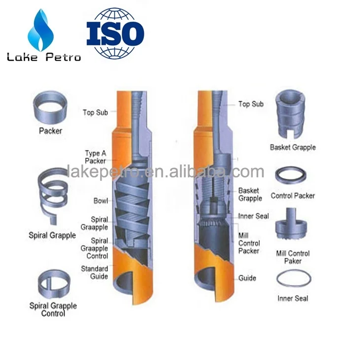
The fish can be removed using special tools and techniques. A Scew-in sub is one of the most common fishing tools. Its modified pin can be used to catch an undamaged fish. The overshot tool because of its versatility is frequently used in fish recoveries. Its simple design includes a circulating and releasing action as well as a 360 degree catch of the fish. Normally the overshot or screw-in sub is connected to the bottom of the bumper sub and fishing jars on the fishing assembly. As the tool is lowered over the fish the top of the fish passes through the tool into the bowl. When the assembly is raised grapples engage the fish at a lower point and it is work free and pulled upward.
In a washed out hole use of a hydraulic Knuckle joint located above the overshot kicks out under pump pressure to increase the sweep of the overshot to facilitate capture of an allusive fish. When the severe wash out, a Wall hook guide run on the bottom of the overshot further improves the search and capture of the fish.
When the fish cannot be dislodged by pulling with the overshot a jarring assembly run in the fishing string can be activated to strike heavy blows either up or down on a stuck fish to free it. The down action is achieved with a Bumper jar; essentially a slip joint with a sliding stroke. The impact enhanced by the weight of drill collars above the Bumper jar results in a sharp blow with the fishing string. Dropping the string quickly produces a sharp downward blow on the fish. This jarring action is especially effective in freeing PC Pipe or a string that is stuck as a result of an upward pull.
In many cases a stuck fish will require a powerful upward jar to free it. Hydraulic fishing jars permit an upward impact. The impact produced by a Hydraulic jar depends on the amount of pull taken on the tool before it trips. As indicated earlier the impact of a Hydraulic jar is enhanced by the weight of Drill collars placed above the tool. A jar accelerator further intensifies the effect of a jar at any depth. It is especially effective in shaft fishing operations where elasticity present in longer drill strings is not available. The use of an accelerator also keeps the energy of the jar impact form being lost a mole.
Essentially Washover operation involve a pipe string that slips over the stuck fish allowing fluid to circulate in the annalist between the fish and the inner wall of the Washover pipe. Fluid under pressure flushes out debris cut lose by the rotary shoe run on the bottom of the Washover pipe. The washed over fish secured by an overshot or a screw-in sub and then be backed and removed to the surface.
Various types of Weatherford shoes are available. Each shoe is custom designed for a particular procedure. Tooth-type shoes for example are recommended when the formation to be cut is relatively soft. When metal such as tool joint or stabilizer blades must be cut the rotary shoe is dressed with Tungsten carbide or diamonds internally, externally or both; tailored specifically for the task. Proper rotary shoe selection requires expertise. An improper choice could severely damage the fish complicating the recovery operation. Occasionally the drill pipe maybe plugged, usually by mud. Cutting the freed drill pipe with a mechanical outside cutter run on the Washpipe would remove the obstruction and establish a clean workable top. Following Washover the Washpipe is pulled up and the shoe removed and replaced by a mechanical Outside cutter. Run into the well and over the freed fish the cutter is engaged. With a slight upward strain cutter knives are fed through the wall of the drill pipe fish and the fish is parted. Rotation is then stopped and the cut piece of fish is recovered and pulled to the surface.
Openhole fishing also involves the retrieval of Junk at the well bottom. Junk is defined as any unwanted material in the hole that hampers operations; such as, accidentally dropped tools, metal debris, parts of equipment including cones from drill bits. A commonly used retrieval tool is the Fishing magnet. Fishing magnets are especially cost effective for retrieving smaller fairish objects such as bit cones, slips and mill cuttings.
Where Junk pieces cannot be caught by a magnet or consistent not fairish metals Weatherford employs specialized Junk baskets depending on the type of formation encountered. These retrieval tools consist of three basic types.
In hard formations a jet powered or Reverse circulating basket is a highly effective tool. Lowered to the bottom it rotates slowly with circulation to flushing settlings from the Junk. A ball is dropped into the drill pipe and pumped down until the ball seeps in the retriever. The flow of the fluid is diverted to the outside the tool which causes two things to occur. It establishes reverse circulation and a venturi effect which then creates a partial vacuum inside the Junk basket. These two forces propel the Junk into the basket. Captured Junk is secured by the hinged Retaining fingers. This action continues until all Junk is removed from the hole.
Open hole fishing is one of the most time consumed operation because it involves a lot of unknown down hole conditions. In order to have successful fishing operation, it is imperative to fully understand about the open hole fishing tool. The video training below provided by Weatherfor is considered as one of the best fishing operation video training. Additionally, the full video transcription is provided to help people understand this topic.
Open hole fishing involves the removal of unwanted objects from the wellbore. The objects can be tools, equipment, and broken pieces of drill, pipe, bits or tribunals. Open hole fishing begins following a backoff and a drill string at or above the stock point of the fish in the wellbore leaving an accessible fish top. The fish can be removed using special tools and techniques.
A screw-in sub is one of the most common fishing tools. Its modified pin can be used to catch an undamaged fish. The overshot tool because of its versatility is frequently used in fish recoveries. Its simple design included circulating and releasing action as well as a 360 degree catch of the fish.
Normally, the overshot or screw in sub is connected to the bottom of the bumper sub and fishing jars on the fishing assembly. As the tool is lowered over the fish, the top of the fish passes through the tool into the ball. When the assembly is raised, grapples engage the fish at a lower point and it is worked free and pulled upward. If the top of the fish is bad, twisted or broken, it should be dressed off to provided clean top so grapple can insecurity firmly. Dressing off is achieved with a skirted or hollow food mill. Several types of mills are available for this purpose and other jobs.
In a washed-out hole, use of a hydraulic knuckle joint located above the overshot kicks out under pump pressure to increase the sweep of the overshot to facilitate capture of an elusive fish. With a severe washout, a wall hook guide run on the bottom of the overshot, further improves the search and capture of the fish. When the fish


 8613371530291