
diverter overshot packer free sample
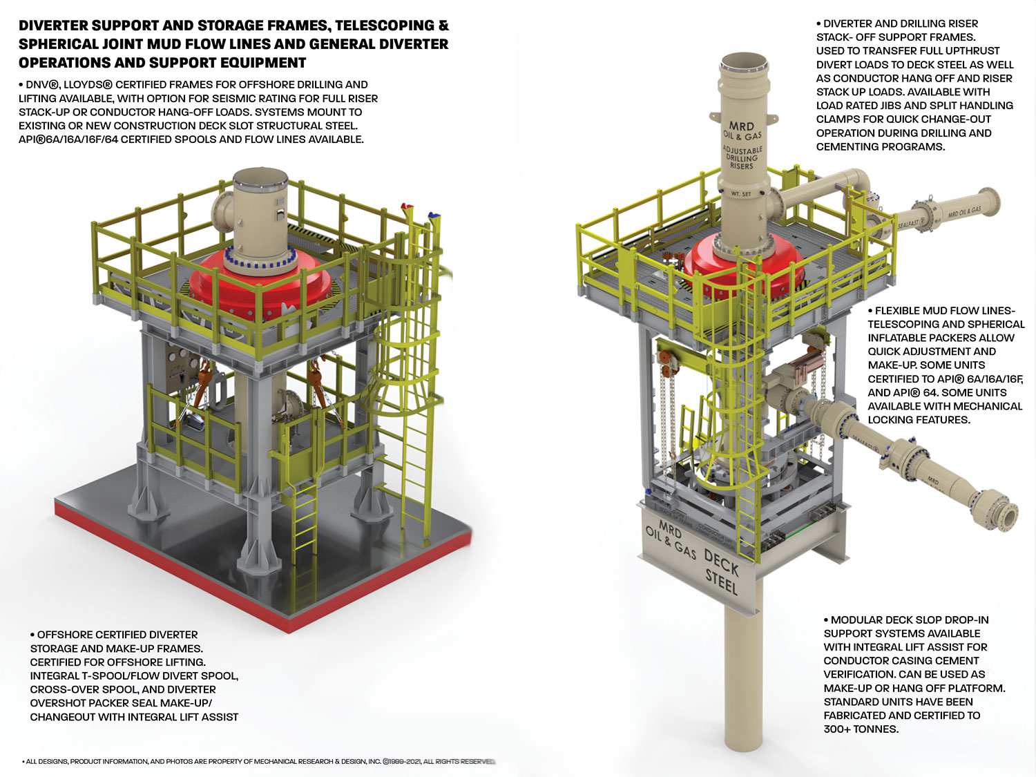
Cameron diverters are fully customizable for your floater and jackup rig operations, respectively. Designed for reliable, efficient use, each system consists of a housing, outlet valves, running tools, controls system, diverter assembly, overshot packers, and storage skids.
The CF-A diverter supports up to 75.5-in rotary tables and has a hang-off capacity of up to 2,500,000 lbm. It uses a single annular packing element with a pressure rating up to 500 psi. The CF-A diverter features four hydraulic locking dogs that reduce hosing and simplify operation. It eliminates the need to secure hoses to the diverter assembly while providing hydraulic fluid for the operations.
The CF-B diverter supports up to 47-in rotary tables and is qualified up to 2,000 psi. Packers can be split and hinged to allow them to be changed out with pipe in the hole. J-slot type running tools are entirely mechanical and require no hydraulics.

Petroleum and natural gas industries — Drilling and productionequipment — Shallow gas diverter equipmentIndustries du pétrole et du gaz naturel — Équipements de forage et de production — Équipement déflecteurpour gaz de surfaceOGP Draft 113354
Foreword..............................................................................................................................................................v Introduction ........................................................................................................................................................vi 1 Scope ......................................................................................................................................................1 2 Normative references ............................................................................................................................1 3 Terms and definitions ...........................................................................................................................1 4 Diverter system equipment...................................................................................................................7 4.1 General purpose ....................................................................................................................................7 4.2 Findings of blowout reports .................................................................................................................7 4.3 Applications of diverter systems .........................................................................................................8 4.4 Design considerations — Land rigs and bottom-supported marine structures .............................8 4.4.1 General....................................................................................................................................................8 4.4.2 Types of annular sealing devices in use .............................................................................................8 4.4.3 Vent outlets ..........................................................................................................................................12 4.4.4 Diverter valves .....................................................................................................................................14 4.4.5 Diverter piping .....................................................................................................................................15 4.4.6 The control system ..............................................................................................................................18 4.4.7 Kill-line facility .....................................................................................................................................18 4.4.8 Additional functions for the diverter system ....................................................................................18 4.5 Design considerations — Floating rigs .............................................................................................18 4.5.1 General..................................................................................................................................................18 4.5.2 Annular sealing devices in use ..........................................................................................................19 4.5.3 Auxiliary diverter system equipment for riser drilling .....................................................................21 4.5.4 Diverter outlets and valves .................................................................................................................23 4.5.5 Diverter piping .....................................................................................................................................23 4.5.6 Control system .....................................................................................................................................24 5 Floating rigs — Specific aspects .......................................................................................................24 5.1 Use of the marine riser ........................................................................................................................24 5.2 Additional functions of the diverter system .....................................................................................27 5.3 Comparison of types of floating support ..........................................................................................27 5.3.1 Moored drill ships ................................................................................................................................27 5.3.2 DP drill-ships ........................................................................................................................................28 5.3.3 Semi-submersibles ..............................................................................................................................28 5.3.4 Conclusion ...........................................................................................................................................28 6 Preparation for shallow gas operations ............................................................................................30 6.1 Call for tender ......................................................................................................................................30 6.2 Important issues ..................................................................................................................................30 6.3 Pre-spud checks ..................................................................................................................................31 6.3.1 Diesel engines and electrical equipment ..........................................................................................31 6.3.2 Kick and loss detection.......................................................................................................................31 6.3.3 Offshore rescue ...................................................................................................................................31 6.3.4 Offshore cooling recommendations ..................................................................................................31 6.3.5 Offshore emergency-release requirements ......................................................................................31 6.3.6 Rig safety equipment ..........................................................................................................................32 6.3.7 Safety precautions ...............................................................................................................................32 6.3.8 Diverter system ....................................................................................................................................32 6.4 Pre-spud meetings ..............................................................................................................................33 6.5 Pre-spud drills ......................................................................................................................................34 6.6 Preparing the response to a shallow-gas flow .................................................................................34 6.6.1 General..................................................................................................................................................34 6.6.2 Reminders ............................................................................................................................................35
6.6.3 Basic well-control aspects ................................................................................................................. 357 Diverter system maintenance ............................................................................................................ 38 7.1 General ................................................................................................................................................. 38 7.2 Certification and recertification ......................................................................................................... 38 7.3 Diverter system piping ........................................................................................................................ 38 7.4 Manufacturer documentation ............................................................................................................. 39 Bibliography ...................................................................................................................................................... 40
Many past shallow-gas kicks turned into uncontrolled blowouts due to the failure of former diverter systems installed several decades ago. Failure is seen as a result of the system"s complexity, its lack of functional reliability and its inability to cope with the severe dynamic loads,
1 ScopeThis International Standard specifies requirements for the selection of the diverter equipment for rigs used todrill shallow-gas-bearing formations. It covers both onshore and offshore drilling operations, and considersalso the auxiliary equipment associated with floating rigs.
3.11control functioncontrol system circuit (hydraulic, pneumatic, electrical, mechanical, or a combination thereof) used to operatethe position selection of a diverter unit, BOP, valve or regulator
3.13diverterdevice attached to the wellhead or marine riser to close the vertical access and to direct any flow into a set ofvent lines and away from the drilling unit
3.18diverter systemassemblage, comprising an annular sealing device, flow control means, vent system components and controlsystem, which facilitates closure of the upward flow path of the well fluid and opening of the vent to theatmosphere
3.54subsea diverterseabed diverterset-up of equipment attached to the bottom of the marine riser and connected to the 762 mm (30 in) subseawellhead housing, designed to close the well in case of shallow-gas influx and to direct it through two subsealateral vent outlets
3.58telescopic joint packertorus-shaped, hydraulically, pneumatically or mechanically actuated, resilient element between the inner andouter barrels of the telescopic joint which serves to retain drilling fluid inside the marine riser
The diverter system is designed to permit the drilling crew to blow down shallow-gas accumulations downwindof the rig. Until a sufficient casing length has been set to allow a well to be shut-in during a kick, the divertersystem is the only line of defence, and is only expected to contain the hazard temporarily, although as long aspossible.
The diverter system is not intended to be a well-control device. It simply allows the flow to be diverted in asafe manner in order to allow enough time to attempt regaining primary control of the well and, should thelatter fail, enough time for proper evacuation of the drilling crew or for proper move-off of the drilling unit fromthe location (floating rigs), until the flow stops due to gas accumulation blow-down, hole bridging, holecollapse, etc.
Blowout inquiries have concluded that the original designs underestimated the fact that shallow-gas blowoutsproduce huge amounts of gas, together with abrasive solids, flowing at very high speed, producing severedynamic loads, and eroding and destroying many parts of the existing diverter systems.
Statistics obtained in the 1990s in Norway have shown that 54 % of shallow-gas blowouts caused severedamage or total loss of the drilling structure and support, due to the failure of the diverter system.Unfortunately, many lives were lost during those dramatic events.
It is therefore of paramount importance to select suitable equipment able to function in a reliable and safemanner, i.e. able to operate whenever required under the worst possible conditions. Diverter equipment shallalso be able to cope with the prevailing dynamic loads and associated effects.
In the insert-type diverter assembly, the insert packing is latched in place into a diverter assembly, which inturn is locked inside the support housing. This housing provides two outlets, one for the mud returns to flowtowards the shakers, one for the diverted fluids to flow out through the vent line(s). The insert is removed priorto pulling or running the bottom-hole assembly (see Figure 1).
This set-up requires a conventional bag-type preventer and a drilling spool (or diverter spool) which aredirectly located on top of the first casing (conductor pipe, drive pipe). This set-up is therefore below the rotarytable and below the flow-line, unlike the insert-type diverter assembly (see Figure 2).
Key1 Bell nipple 6 Vent line2 Flow line 7 Diverter spool3 Fill-up line 8 Hydraulically operated full opening valve4 Annular packing element 9 Drive / Conductor pipe5 Standard bag-type preventer
insert-type packer usually closes fast (a few seconds), while the operation of the vent and flow- line valves takes much longer (> 40 s), hence imposing a sequencing system to prevent closure of the packer prior to proper operation of the valves;
The standard hook-up option eliminates the need for a flow-line valve, as the flow-line is located at the level ofthe bell nipple, well above the diverter set-up.
The use of an overshot packer, required for length adjustment below the diverter system, is also eliminated,hence removing a potential leak point at pack-off level. Conversely, this adjustment joint and its packer can beused without risk above the bag preventer, as it will not experience any gas flow pressure.
Another safe alternative is to use an integral diverter assembly, which integrates the diverter spool and theannular packing into a single piece of equipment.
In this system the motion of the annular piston is used, in one stroke, to first open the vent lines and then stopthe upward flow. The flow-line is located at the level of the bell-nipple, well above the integral diverterassembly, hence eliminating the need for a specific flow-line valve (see Figures 3 and 4).
Several types of valve are commonly associated with diverter systems: gate valves, ball valves, switchablethree-way target valves, knife valves, valves integral to the diverter unit and sometimes burst disks.
For insert-type diverter systems requiring actuation of valves on both shaker and vent lines, an interlocksystem shall prevent the diverter from closing before the valves are in the correct position (i.e. shaker valveclosed, vent-line valve open). This is of paramount importance with these systems, where the response timeof the insert packer is much lower than that of the shaker and vent-line valves [usually less than 10 s to closeon a 127 mm (5 in) drill pipe].
Actuators fitted to a diverter valve shall be sized to open the valve at least with the rated working pressure(WP) of the diverter system applied across the valve.
The safest and most reliable option is the integral diverter system (see Figures 3 and 4) in which the physicalneed for valves is eliminated. In such a system, the shaker and fill-up lines are located far above the divertersystem within the rig sub-structures, and do not require any shut-off valves.
Diverter piping shall consequently be sized and its layout designed such that the anticipated back-pressure,calculated with realistic gas flow rates, do not exceed the rated working pressure of the diverter system, donot exceed the design pressure of other equipment, and do not place undue pressure on the wellbore.
At the rig site location, the diverter vent-lines shall extend a sufficient distance in the most appropriatedirection from the rig to permit safe venting of diverted well fluids.
Consequently, the minimum required nominal internal diameter (ID) of diverter outlets and vent-lines shall be355,6 mm (14 in). The piping wall thickness shall not be less than 19,05 mm (0,75 in).
The diverter control system shall be designed and sized in accordance with API 16D:2005, Section 5.5. It shallcontain the minimum of functions. Preferably, a one-button or lever-activated function shall operate the entirediverter system.
A 38,1 mm (1½ in) hydraulic operating line should be used for diverter systems with a 1½ in NPT closingchamber port size. The hydraulic line for the opening chamber port may be 25,4 mm (1 in).
Many shallow-gas blowout reports have mentioned failures of the pneumatic control system used to operatediverter valves (e.g. failure to work as required when valves stems are blocked with solids). A pneumaticcontrol system shall therefore be avoided on rigs, if possible.
Each diverter system should incorporate a kill-line facility (including a check valve) to allow pressure-testing ofthe annular packing element closed on open hole, with no pipe in hole. This facility can also be used toperiodically flush the system clean.
Another advantage of a kill-line facility is to pump water through the diverter system during a gas-flow divertingoperation, in order to wet the gas and accordingly reduce the fire risk.
The use of a diverter system (alone or combined with a BOP set-up) should be considered on multi-wellplatforms, due to potential hazards such as collision with adjacent wells or surface-gas accumulations due topoorly cemented casings.
Though many parts of the diverter system are identical to those used on land rigs and bottom-supportedmarine structures, others are specific to floating units and are reviewed hereafter.
When drilling shallow-gas-bearing formations with a riser, two types of sealing device are used: the surfaceinsert-type diverter assembly and the subsea diverter.
By design, this system is basically similar to the system used on land rigs and bottom-supported marinestructures. The diverter support housing is permanently fixed to the drill-floor substructure below the rotarytable at the upper end of the marine riser system, and provides outlets for the shakers and for ventingpurposes. The diverter assembly is locked down inside the housing, and the insert packer is locked inside thelatter.
For floating supports, the possibilities to improve the surface vent-lines network and routing being substantiallyreduced, the subsea diverter system is a safer alternative. The basic set-up includes, from top to bottom: aflex joint, an annular BOP (or a shear ram unit), a diverter spool and a riser hydraulic connector (seeFigure 6).
If the subsea diverter option is selected, it is recommended to hook up a riser booster line above the upperclosing unit (bag or shear ram), to eliminate any gas which has entered the riser before complete well shut-off.An additional diverter system (e.g. the basic insert-type assembly) is required at surface to deal with this gasinflux (see also 4.5.2.3 and 5.2).
Prior to choosing this option, it is important to look carefully at the water depth and the type of support vesselwhich has been selected. Even after its transit through the water column, gas still represents a potentialexplosion and fire hazard, mainly as it concentrates in the moon-pool area. With gas being vented at seabedlevel and percolating up to surface, the subsea diverter is probably not the best choice with a drill-ship inshallow water depths.
Key Key1 539,7 mm (21 1/4’’) Flex Joint 1 539,7 mm (21 1/4’’) Flex Joint2 539,7 mm (21 1/4’’) Annular BOP 2 539,7 mm (21 1/4’’) Annular BOP3 539,7 mm (21 1/4’’) Diverter spool w/ integral valving 3 539,7 mm (21 1/4’’) Shear ram and 304,8 mm (12’’) outlets 4 539,7 mm (21 1/4’’) Diverter spool4 Guide structure 5 Outlet nozzle5 762mm (30’’) Hydraulic connector 6 762 mm (30’’) Hydraulic connector
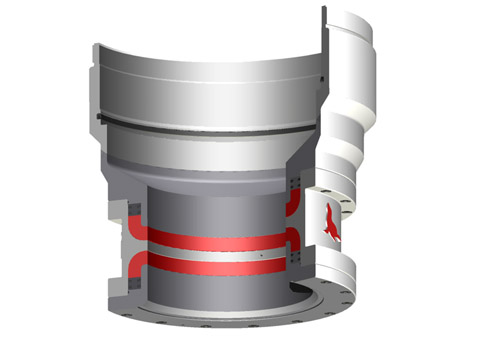
NOTE The diverter is shown here in the drilling mode. When the diverter closes in case of gas influx, the piston movesupward, opening the flow path to the vent line while closing the flow path to the flow line.
Should surface diverting be considered as too hazardous (in particular if the integral diverter system is notavailable), the requirement for safe operation is to use the subsea diverter. Its use depends however on thewater depth at the drilling location, the virulence of reported local shallow-gas events, the type of supportvessel contemplated and the competence of the chartered drilling contractor.
The insert-type diverter system should only be used in conjunction with a subsea diverter or with a BOP stack,to circulate and vent out any gas trapped in the riser (see 5.2).
The same comments for land rigs and bottom-supported marine structures given in 4.4.3 and 4.4.4 apply tovent outlets and diverter valves for floating rigs.
On floating rigs (as for land rigs and bottom-supported marine structures), since the size and number of vent-lines have a great influence on surface and downhole hazards, two properly sized vent-lines shall be used.The minimum nominal ID of diverter outlets and vent-lines shall be 355,6 mm (14 in).
Key1 Flow selector always open2 Diverter with integral valve functions3 To Shale shaker4 To Vent lines5 To Starboard vent line6 To Port vent line
The diverter control system shall be designed and sized according to API 16D:2005, Section 5.5. Pneumaticcontrol systems shall be avoided on rigs working in shallow-gas-prone areas.
Each operating company has its own drilling policy with respect to using (or not) the marine riser while drillingshallow-gas-prone formations. The general mistrust of existing diverter systems on most floating rigs has ledsome operators to adopt a riserless approach. The following comments can be made.
Whatever the pros and cons of riser use, a preliminary careful and thorough review of the reliability andcapacity of the rig diverter system (see 4.5.2) and of the reliability and capacity of the emergency-releasesystem of the floating-support mooring lines can provide decisive criteria to assist in selecting the beststrategy.
Gas can inadvertently enter the riser when the BOP is shut-in on a kick. Gas can also enter the riser if the rams leak after the BOP is closed. Using the diverter system, the gas in the riser can be safely removed and diverted overboard,
After a kick circulation is completed, some compressed trapped gas can remain between the closed BOP and the choke-line connection. This gas will tend to migrate into the riser when the BOP is re-opened. Using the diverter system, this gas can also be safely removed and diverted overboard.
a competent drilling crew, having past experience in shallow-gas drilling, purposely trained and familiar with the diverter equipment and its proper testing, maintenance, and operation;
Prior to drilling a shallow-gas formation, all the diverter system components shall be inspected and tested toascertain proper installation and function. As a minimum, the following tasks shall be carried out.
Ensure that any fill-up line which can be exposed to the gas flow is protected with a check valve; this line and check valve shall have a WP equivalent to that of the diverter system.
d) Simulate loss of rig air supply to the diverter control system and determine effects, if any, on the diverter system, valves, and back-up systems.
On a routine basis, when in primary diverter service (no BOP installed), function tests should be performeddaily using the driller’s panel to verify that functions are operable. Fluid should be regularly pumped througheach diverter line during drilling operations to ensure that they are clear of obstructions at all times.
review all preliminary checks related to, among others, the diverter system, kick detection equipment, kill mud volumes, emergency power supply, safety, rescue and emergency equipment, emergency communication systems, mooring equipment if applicable, etc.;
All concerned personnel should therefore be familiar with the diverter system components and installation,and should be capable of reacting quickly and efficiently to potential situations requiring use of the diverter.
Any defect or problem with equipment or personnel identified during any of these pre-spud drills should beimmediately reported and dealt with before drilling is permitted to start. Thereafter, drills should be conductedat appropriate intervals to ensure personnel are capable of quickly and competently reacting to situationsrequiring use of the diverter.
If practically feasible, a tentative well kill should be attempted immediately with heavy kill mud and themaximum pumping rate available, after the diverter system has been activated, to try to stop the gas flowdownhole, prior to complete well unloading.
A schedule for routine inspection and maintenance of diverter systems equipment should be prepared andmaintained by the rig operating personnel. Specific guidelines for each diverter component or sub-systemshould be based on installation, operation and maintenance manuals provided by the equipmentmanufacturer.
During diverter function tests, observe all components of the diverter system including the diverter, valves, valve actuators, piping, and control panel to verify that there are no leaks in the system. If a leak is discovered, it should be repaired immediately.
All diverter equipment shall be maintained with original equipment manufacturer’s (OEM) genuine or approved spares and shall be operated and tested in accordance with that manufacturer"s recommended procedures. Major repairs, overhaul on and recertification of diverter equipment shall be performed either by the OEM or an alternative provider, but then only when approved by the OEM.
A visual inspection, a body-pressure test and a full-function test shall be carried out once a year on a diverter test stump at surface, in accordance with the manufacturer"s specification for such a test and witnessed by a certified third party. Results of the inspections and tests, including follow-up, shall be documented, providing full traceability and be part of the formal service history.
At least every five years, the diverter system components shall be inspected for repair or remanufacturing by the OEM or OEM-approved service provider. Upon completion of the inspection, the OEM shall provide a Certificate of Conformance (COC).
The wall thickness on all undesirable turns and bends (if any) in the diverter system piping should be checkedat least annually and after each use of the system to divert a well kick. Erosion of metal from the turns andbends can be severe if sustained flows of gas-associated solids are diverted through the system.
Installation, operation and maintenance manuals furnished by the manufacturers of the various components ofthe diverter system should be readily available for training, reference, and use by maintenance personnel.
This invention relates in general to diverters and blowout preventer systems for drilling rigs. In particular, the invention relates to diverter and blowout preventer systems and methods for use with bottom supported offshore drilling rigs.
Diverter systems for bottom supported offshore drilling rigs are known in which a diverter element is provided in the support housing attached to the support beams beneath the drilling rig rotary table. Such diverter systems have provided for a vent line and a flow line in the permanent housing beneath the rotary table. Such systems have required external valve systems in the vent line to assure that when the diverter in the permanent housing opens the fluid system to the vent line, the flow may be directed away from the drilling rig. In such prior art systems, a spacer spool has been typically provided beneath the support housing and a thirty (30) inch overshot connection has been provided between the spacer spool and the thirty (30) inch outside diameter drive pipe or structural casing.
Fatal and costly accidents have resulted from the complexity of prior art diverter systems described above. Typical prior art diverter systems have included an annulus closing device, external vent and flow line valves, actuators, limit switches and sequenced controls. This complicated valving and piping of the prior art has been further complicated by the inherent risks of manipulating loose packer inserts into the diverter itself. The complexity of the prior art systems has invited a variety of human error and equipment malfunctions.
One problem with the prior art systems has involved the use of external valving in the diverter system. Valves which are external to the diverter unit not only add clutter to the diverter system and the rig configuration, but also require multiple control functions which are required to operate properly. For example, the prior art diverter system valves have required an actuating pressure signal that is regulated to a discrete pressure level different from the operating pressure level of the diverter unit. The need for separate and different control functions executed in only one safe sequence has required separate pressure regulators and connecting components that are in different locations on the underside of the rig floor. Such a requirement has invited mistakes and malfunctions.
In addition to the problem of multiple control functions, there has existed problems with crossed connections in prior art diverter systems. Misconnection of control lines can cause a valve to be closed when it should be open which could result in an explosion in the diverter or breach of the casing.
Another problem of the prior art diverter systems has been exposure of delicate parts such as hydraulic tubing and fittings, limit switches, mechanical linkages and valve actuators to the rig work area. Such exposure has in the past caused breakage and damage to such parts. System malfunctions which result from damage to exposure can be catastrophic.
Another problem of prior art diverter systems has been the result of vent line blockage. Because the vent valve has been remote from the diverter unit itself, a stagnant space has existed at a critical location in the vent line. Buildup of solids and caking of mud in such a dead space may cause the critically important vent line to be choked off. A restricted or shut-off vent line may cause a dangerous pressure increase while being called upon to divert.
Still another problem of prior art diverter systems has involved the use of component sources from a number of different manufacturers. The annulus closing device, vent and flow line valves, actuators, sequencing devices and control system components have typically been provided by different manufacturers. Rig operating personnel are usually burdened with devising the vent line valve circuit interconnecting the components (which are often widely physically separated when installed) and stocking a varied assortment of spare parts using extraordinary caution to avoid misconnections and keeping a number of rig personnel trained to operate and maintain a diverse assortment of complicated components.
Still another problem of prior art diverter systems for bottom supported rigs has been the requirement of a high pressure valve in the vent line. Closure of such a valve has enabled the diverter unit to be converted to a blowout preventer after sufficient casing pressure integrity has been established. However, if this valve should inadvertently be closed during an attempt to divert, breach of the casing or explosion of the diverter system could threaten the safety of the rig itself.
Still another problem of prior art diverter systems has been the result of valve mismatch. While many different types of valves have been used in diverter systems, there has been no single valve that is especially well suited to the particular application of a diverter system. Selection of the type, size and rating of such valves has been a vexing puzzle for designers of rig valve systems which has been required to be solved usually when a new drilling rig is being built.
Another important disadvantage of the prior art diverter systems has been the necessity to stop drilling operations and manipulate packer inserts to facilitate annulus shut-off. Such a necessity has not only been a time consuming task, it has presented very real hazards. One such hazard has been the problem of forgotten inserts. Often in the course of determined efforts to drill ahead, fetching, installing and latching the packer insert is overlooked. Without such an insert there is no diverter protection. If the insert is in place, but not latched down in some prior art diverter systems, the packer insert is potentially a dangerous projectile.
A second problem resulting from the use of packer inserts has been the problem of an open hole hazard. There has been no protection from the insert type diverter against uncontrolled well fluid flows. Such lack of protection has left a serious safety gap in the drilling operation.
Still another problem of the use of packer inserts in the prior art diverter systems has been the problem of forgotten removal. If unlatch and removal of the packer insert has been inadvertently overlooked before pulling drill pipe from the hole, centralizers or the bottom hole assembly may be run into the insert, thereby endangering the drilling crew and equipment.
Still another problem of the use of packer inserts in the prior art drilling systems has been the problem of exploding packers. If during testing, the standard packer is not reinforced by an insert and/or a pipe in the hole, the hydraulic fluid pressure may cause the packer to explode, thus jeopardizing the safety of the crew.
Perhaps the most important problem of the prior art diverter systems has been the inherent risk of pressure testing in-situ. Pressure testing of prior art diverter systems has been accomplished by overriding the safety sequencing in the valves so that the vent line valve is closed simultaneously with closure of the annulus. Disastrous results have been experienced when the safety overriding mechanism has been unintentionally left in place when testing was complete and drilling was resumed.
It is therefore a primary objective of this invention to overcome the disadvantages and problems and inherent safety risks of the prior art diverter systems.
It is another object of the invention to provide a diverter system for a bottom founded offshore drilling rig in which the vent line is always open. In other words, it is an object of the invention to provide a system having no valves or other obstructions in the vent line, thereby avoiding the complexity of external valves, valve actuators and valve control functions.
It is still another object of the invention to provide a single control function for operation of the diverter system. In other words, it is an object to provide on command, a single signal to one component for performing an inherently safe execution of the rerouting of flow of a well kick.
It is another object of the invention to provide a system having no stagnant space, a system in which the vent flow is immediately opened when the diverter system begins to divert fluid away from the well. Avoiding the stagnant space in the system, prohibits caking of solids that may obstruct or shut-off vent flow.
It is still another object of the invention to provide an annular packing unit in a diverter system thereby affording many important safety and operational advantages such as the avoidance of providing inserts when running in and pulling out of the hole during the drilling operations. Potentially fatal mistakes of forgetting to fetch, install, remove and latch down inserts are avoided. Such advantages also include the effect of rig time saved.
Another important advantage of the diverter system according to the invention is to provide a diverter system packing unit which can close on open bore thus providing ready assurance of safety in the event of excessive well flow while there is no pipe in the hole and thereby eliminating a serious gap in the safety of the drilling operation of prior art diverter systems.
Another important advantage of the invention is to provide for safe testing with a packing unit which does not directly contact hydraulic fluid during actuation, thereby eliminating the dangers of exploding packers.
It is another object according to one embodiment of the invention to provide telescoping spools above and below the diverter blowout preventer unit providing a system which is versatile and time efficient.
It is another object of the invention to provide telescoping spools between the diverter and blowout preventer system which have high strength quick-connect couplings permitting reliable, fast nippling up and down.
It is another object according to an alternative embodiment of the invention to provide a telescoping spool below the diverter/blowout preventer unit and fastening the diverter/blowout preventer unit to the bell nipple or permanent housing providing a system which is versatile and time efficient.
It is another object of the invention to provide a telescoping spool between the diverter and the blowout preventer system which has high strength quick, connect couplings permitting reliable, fast nippling up and down.
The above identified objects of the invention as well as other advantages and features of the invention flow from a novel system adapted for alternative use as a diverter or a blowout preventer for a bottom supported drilling rig. The system is adapted for connection to a bell nipple or permanent housing attached to rig structure members beneath the drilling rig rotary table. The permanent housing has an outlet connectable to the rig fluid system flow line.
The system according to the invention includes a fluid flow controller (e.g., diverter/blowout preventer) having a housing with a lower cylindrical opening and an upper cylindrical opening and a vertical flow path therebetween and a first outlet passage provided in the housing wall. An annular packing element is disposed within the housing. An annular piston means adapted for moving from a first position to a second position is provided whereby in the first position the piston means wall prevents interior fluid from communicating with the outlet passage in the housing wall and in the second position, the piston means wall allows fluid communication of interior fluid with the outlet passage and urges the annular packing element to close about an object extending through the bore of the housing or to close the vertical flow path through the housing in the absence of an object in the vertical flow path. Means are provided in the system for connecting alternatively a blind flange, a vent line or choke/kill line to the first outlet passage provided in the housing wall.
Advantageously, the lower joining means at the lower end of the lower telescoping spool is an overshot connection. The upper connection means at the upper end of the lower telescoping spool is preferably a snap joint connector. The lower connection means of the upper telescoping spool is likewise preferably a snap joint connector. Hydraulic latch means provided on the permanent housing connect the upper part of the upper telescoping spool to the permanent housing. The means for alternatively connecting a vent line, a blind flange or a choke/kill line to the first outlet passage in the controller housing wall comprises a spool extending from the outlet passage and a clamp or flange fastening means for connecting the spool to alternatively the vent line, a choke/kill line or a blind hub or flange.
Also, according to the invention, a method is provided for installing a system adapted for alternative use as a diverter or as a blowout preventer for a bottom supported drilling rig beneath the permanent housing attached to rig structure members supporting the drilling rig rotary table after structural casing has been set in a borehole. The method comprises the steps of lowering through the rotary table a collapsed and pinned lower telescoping spool having a lower joining means at its lower end and an upper connector means at its upper end. The lower joining means is joined at the lower end of the lower spool to the structural casing in the borehole.
A fluid flow controller having a first housing wall outlet and adapted for alternative use as a diverter or blowout preventer is moved to a drilling rig subsupport structure beneath the rotary table. The controller is fastened to the subsupport structure after the controller is substantially aligned with the bore of the rotary table above and the lower telescoping spool below. The lower telescoping spool is unpinned and stroked out until the connector means at its upper end connects with the lower end of the controller. A collapsed and pinned upper telescoping spool is lowered through the rotary table. The upper telescoping spool has a lower connector means at its lower end which is connected to the upper end of the controller by means of its lower connector means. Next, the upper telescoping spool is unpinned and stroked out until the upper end of the upper telescoping spool connects with the permanent housing.
A vent line connection to the wall outlet of the controller housing results in a completed system which may be used as a diverter system for drilling the borehole for the conductor string through the structural casing.
The system which results from the above steps may be used as a diverter during drilling through the conductor string. The method described above may further comprise the steps of removing the clamped or flanged vent line connection at the wall outlet of the controller housing, installing a reducer hub or flange to a choke/kill line, and making up the reducer hub or flange to the wall outlet of the controller housing. The system which results from the above series of steps may be used as a blowout preventer during drilling through the conductor string.
Advantageously according to the alternative embodiment of the invention, the lower joining means at the lower end of the lower telescoping spool is an overshot connector. The upper connection means at the upper end of the lower telescoping spool is a snap joint connector. The lower connection means of the permanent housing is a hydraulic latch means for connecting the upper cylindrical opening of the fluid flow controller to the permanent housing. The means for alternatively connecting a vent line, a choke/kill line or a blind flange to the first outlet passage in the controller housing wall comprises a spool extending from the first outlet passage and a clamp or flange fastening means for connecting the spool alternatively to the vent line, the blind clamp or flange or to the choke/kill line.
Also, according to the alternative embodiment of the invention, a method is provided for installing a system adapted for alternative use as a diverter or as a blowout preventer for a bottom supported drilling rig beneath the permanent housing attached to rig structure member supporting the drilling rig rotary table after structural casing has been set in a borehole. The method comprises the steps of lowering through the rotary table a collapsed and pinned lower telescoping spool having a lower joining means at its lower end and an upper connection means at its upper end. The lower joining means at the lower end of the lower spool is joined to the structural casing in the borehole.
A fluid flow controller having a first housing wall outlet spool and adapted for alternative use as a diverter or blowout preventer is moved to a drilling rig subsupport structure beneath the rotary table so that the rotary table is located above the controller and the lower telescoping spool is located below the controller. A handling or running tool is used to raise the fluid flow controller until an upper end of the controller connects with the permanent housing. The lower telescoping spool is unpinned and stroked out until the connection means at its upper end connects with the lower end of the controller. A vent line connection to the first wall outlet spool of the controller housing results in a completed system which may be used as a diverter system for drilling the borehole for the conductor string through the structural casing.
The method according to the alternative embodiment of the invention further includes steps after a smaller diameter casing has been cemented into the well. The steps comprise disconnecting the clamped or flanged vent line connection to the wall outlet spool of the controller housing, disconnecting the fluid flow controller from the lower telescoping spool and removing the flow controller to a stowed position beneath the rig floor, installing a blind hub or flange to the wall outlet spool, collapsing and pinning the lower telescoping spool and removing the lower spool through the rotary table, installing a low pressure spacer spool having an overshot sub at its lower end to the mandrel, installing a low pressure blowout preventer stack to the low pressure spacer spool, installing either a second telescoping or hard spool through the rotary table above the low pressure blowout preventer stack, and connecting the second spool to the permanent housing. The blind hub or flange in the steps above for the low pressure blowout preventer system could be removed and a choke/kill line could be installed to the first wall outlet spool.
FIG. 1 illustrates the apparatus and method for installing a diverter/BOP system between the bell nipple or permanent housing 30 attached to support beams 14 beneath the drilling rig floor. Rotary table 12 has a bore which may be opened to coincide with that of the permanent housing thereby allowing tubular members to be inserted through the bore of the rotary table 12 and the permanent housing 30 to positions below. Permanent housing 30 has a flow line 16 connected to an opening in its wall. A fill up line (not illustrated) may be similarly connected to another hole in the wall.
Returning now to FIG. 1, the fluid flow controller 32 is disposed and stored in the drilling rig in a sublevel illustrated by support memher 54. After the initial opening in the sea floor has been provided such as illustrated by borehole 46, a structural casing 48 is provided therein typically having a thirty (30) inch outside diameter. A lower telescoping spool 40 is lowered through the bore of the rotary table 12 through the permanent housing 30 to the proximity of the structural casing 48. A handling tool (not illustrated) lowers the lower telescoping spool until the overshot connection 50 at the lower part of the lower telescoping spool 44 engages the outer diameter of the structural casing 48 providing an overshot connection to it.
The system illustrated in FIG. 2 may advantageously be used as a diverter system during drilling through the structural casing 48 for the purpose of providing the hole for the conductor casing. According to the invention, a failsafe system is provided requiring no external valving with all the inherent advantages of simplicity, ruggedness and the ability to close about objects in the borehole or even close on open hole. The system is assured of diverting while closing the vertical flow path to the fluid system flow line in the event of a kick in the well.
Turning now to FIG. 3, an illustration of the system is presented after the conductor casing 70 has been run and cemented within the structural casing 48. Typically, the conductor casing 70 has an outside diameter of twenty (20) inches. The conductor casing is provided after the lower telescoping spool 40 has had its overshot connection removed from the structural casing 48 and has been stroked upwardly and pinned until the conductor casing 70 may be installed within the structural casing 48. After the conductor casing has been installed, the top of it is cut off and an adapter spool 71 is provided having an upwardly facing mandrel 72 which has an outside diameter equal to that of the structural casing. In other words, the mandrel 72 will typically have a nominal diameter of thirty (30) inches, similar to that of the structural casing.
After the mandrel has been installed, the lower telescoping spool may be unpinned and stroked downward until the overshot connection 50 fits about the outside diameter of mandrel 72 providing a fluid tight connection. In this configuration of FIG. 3, further drilling through the conductor casing 70 may continue in the diverter mode. In other words, the clamp or flange 57, vent line 56 and blast selector/deflector 58 may remain in place if the flow controller 32 is to be used as a diverter.
FIG. 5 illustrates an alternative embodiment of the apparatus and method for installing a fluid flow controller or diverter/BOP system 32 to the permanent housing 30. The permanent housing 30 is attached to the support beams 14 beneath the drilling rig floor. The bore of rotary table 12 is aligned with the permanent housing 30 thereby allowing tubular members to be inserted via the rotary table 12 and the permanent housing 30 to positions below. A handling tool 80 is shown inserted through the bore of the rotary table 12 and releasably secured to the fluid flow controller 32.
In FIG. 5, after the initial opening of the sea floor has been provided such as illustrated by borehole 46, a structural casing 48 is provided therein typically having a thirty (30) inch outside diameter. A lower telescoping spool 40 is lowered via the bore of the rotary table 12 through the permanent housing 30 to the proximity of the structural casing 48. The lower telescoping spool 40 has a lower barrel 92 and an upper barrel 94. The overshot sub 50 at the lower part 44 of the lower telescoping spool 40 is joined with the outer diameter of the structural casing 48 providing a lower joining means.
The system illustrated in FIG. 6 may advantageously be used as a diverter system during drilling through the structural casing 48 for the purpose of providing the hole for the conductor casing. According to the invention, a failsafe system is provided requiring no external valving with all the inherent advantages of simplicity, ruggedness and the ability to close about objects in the borehole or even close an open hole. The system will divert upon closing the vertical flow path to the fluid system flow line 16 in the event of a kick in the well.
Turning now to FIG. 7, an illustration of the low pressure blowout preventer system is presented after the conductor casing (not shown), similar to conductor casing 70 shown in FIGS. 3 and 4, has been run and cemented within the structural casing 48. Typically, the conductor casing has an outside diameter of twenty (20) inches. The conductor casing is provided after the lower telescoping spool 40, as shown in FIGS. 5 and 6, has had its overshot sub 50 removed from the structural casing 48 and has been stroked upwardly and pinned until the conductor casing is installed within the structural casing 48. After the conductor casing has been installed, the top of the conductor casing is cut off and an adapter spool 71 and an upwardly facing mandrel 72 are installed. The mandrel 72 will typically have a nominal diameter of thirty (30) inches, similar to that of the structural casing 48.
After the mandrel 72 has been installed and the lower telescoping spool 40 has been removed, a low pressure spacer spool 82 having an overshot sub 84 fits about the outside diameter of mandrel 72 providing a fluid tight connection. A low pressure ram blowout preventer stack 86 may then be connected to the low pressure spacer spool 82 after which a telescoping spool 88 may be connected between the low pressure ram blowout preventer stack 86 and the fluid flow controller 32 or, alternatively, directly connected to the permanent housing 30. Typically, the telescoping spool 88 has an outside diameter of thirty (30) inches. Alternatively, a hard spool (not shown) could be used instead of telescoping spool 88.
This invention relates in general to diverters and blowout preventer systems for drilling rigs. In particular, the invention relates to diverter and blowout preventer systems and methods for use with bottom supported offshore drilling rigs.
Diverter systems for bottom supported offshore drilling rigs are known in which a diverter element is provided in the support housing attached to the support beams beneath the drilling rig rotary table. Such diverter systems have provided for a vent line and a flow line in the permanent housing beneath the rotary table. Such systems have required external valve systems in the vent line to assure that when the diverter in the permanent housing opens the fluid system to the vent line, the flow may be directed away from the drilling rig. In such prior art systems, a spacer spool has been provided beneath the support housing and a thirty (30) inch overshot connection has been provided between the spacer spool and the thirty (30) inch outside diameter drive pipe or structural casing.
Fatal and costly accidents have resulted from the complexity of prior art diverter systems described above. Typical prior art diverter systems have included an annulus closing device, external vent and flow line valves, actuators, limit switches and sequenced controls. This complicated valving and piping of the prior art has been further complicated by the inherent risks of manipulating loose packer inserts into the diverter itself. The complexity of the prior art systems has invited a variety of human error and equipment malfunctions.
One problem with the prior art systems has involved the use of external valving in the diverter system. Valves which are external to the diverter unit not only add clutter to the diverter system and the rig configuration, it has also required multiple control functions which are required to operate perfectly. For example, the prior art diverter system valves have required an actuating pressure signal that is regulated to a discrete pressure level different from the operating pressure level of the diverter unit. The need for separate and different control functions executed in only one safe sequence has required separate pressure regulators and connecting components that are in different locations on the underside of the rig floor. Such a requirement has invited mistakes and malfunctions.
In addition to the problem of multiple control functions, there has existed problems with crossed connections in prior art diverter systems. Misconnection of control lines can cause a valve to be closed when it should be open which could result in an explosion in the diverter or breach of the casing.
Another problem of the prior art diverter systems has been exposure to the marine environment of delicate parts such as hydraulic tubing and fittings, limit switches, mechanical linkages and valve actuators. Such exposure has in the past caused breakage and damage to such parts. System malfunctions which result from damage to exposure can be catastrophic.
Another problem of prior art diverter systems has been the result of vent line blockage. Because the vent valve has been remote from the diverter unit itself, a stagnate space has existed at a critical location in the vent line. Buildup of solids and caking of mud in such a dead space may cause the critically important vent line to be choked off. A restricted or shut-off vent line may cause a dangerous pressure increase while being called upon to divert.
Still another problem of prior art diverter systems has involved the use of component sources from a number of different manufactures. The annulus closing device, vent and flow line valves, actuators, sequencing devices and control system components have typically been provided by a different manufacturer. Rig operating personnel are usually burdened with devising the vent line valve circuit interconnecting the components (which are often widely physically separated when installed) and stocking a varied assortment of spare parts using extraordinary caution to avoid misconnections and keeping a number of rig personnel trained to operate and maintain a diverse assortment of complicated components.
Still another problem of prior art diverter systems for bottom supported rigs has been the requirement of a high pressure valve in the vent line. Closure of such a valve has enabled the diverter unit to be converted to a blowout preventer after sufficient casing pressure integrity has been established. However, if this valve should inadvertently be closed during an attempt to divert, breach of the casing or explosion of the diverter system could threaten the safety of the rig itself.
Still another problem of prior art diverter systems has been the result of valve mismatch. While many different types of valves have been used in diverter systems, there has been no single valve that has been designed expressly for or is especially well suited to the particular application of a diverter system. Selection of the type, size and rating of such valves has been a vexing puzzle for designers of rig valve systems which has been required to solve usually when a new drilling rig is being built.
Another important disadvantage of the prior art diverter systems has been the necessity to stop drilling operations and manipulate packer inserts to facilitate annulus shut-off. Such a necessity has not only been a time consuming task, it has presented very real hazards. One such hazard has been the problem of forgotten inserts. Often in the course of determined efforts to drill ahead, fetching, installing and latching the packer insert is overlooked. Without such an insert there is no diverter protection. If the insert is in place, but not latched down in prior art diverter systems, the packer insert is potentially a dangerous projectile.
A second problem resulting from the use of packer inserts has been the problem of open hole hazard about the pipe in the hole while the insert is being installed or removed. There has been no protection from the insert type diverter against uncontrolled well fluid flows. Such lack of protection has left a serious safety gap in the drilling operation.
Still another problem of the use of packer inserts in the prior art diverter systems has been the problem of forgotten removal. In unlatch and removal of the packer insert has been inadvertently overlooked before pulling drill pipe from the hole, centralizers or the bottom hole assembly may be run into the insert, thereby endangering the drilling crew and equipment.
Still another problem of the use of packer inserts in the prior art drilling systems has been the problem of exploding packers. If during testing, the standard packer is not reinforced by an insert and/or a pipe in the hole, the hydraulic fluid pressure may cause the packer to explode, thus jeopardizing the safety of the crew.
Perhaps the most important problem of the prior art diverter systems has been the inherent risk of pressure testing in-situ. Pressure testing of prior art diverter systems has been accomplished by overriding the safety sequencing in the valves so that the vent line valve is closed simultaneously with closure of the annulus. Disastrous results have been experienced when the safety overriding mechanism has been unintentionally left in place when testing was complete and drilling was resumed.
It is therefore a primary objective of this invention to overcome the disadvantages and problems and inherent safety risks of the prior art diverter systems.
It is another object of the invention to provide a diverter system for a bottom founded offshore drilling rig in which the vent line is always open. In other words, it is an object of the invention to provide a system having no valves or other obstructions in the vent line, thereby avoiding the complexity of external valves, valve actuators and valve control functions.
It is still another object of the invention to provide a single control function for operation of the diverter system. In other words, it is an object to provide on command, a single signal to one component for performing an inherently safe execution of the rerouting of flow of a well kick.
It is another object of the invention to provide a system having no stagnant space, a system in which the vent flow is immediately opened when the diverter system begins to divert fluid away from the well. Avoiding the stagnant space in the system, prohibits caking of solids that may obstruct or shut-off vent flow.
It is still another object of the invention to provide an annular packing unit in a diverter system thereby affording many important safety and operational advantages such as the avoidance of providing inserts when running in and pulling out of the hole during the drilling operation thereby avoiding potentially fatal mistakes of forgetting to fetch, install and latch down inserts. Such advantage also includes the effect of rig time saved.
Another important advantage of the diverter system according to the invention is to provide a diverter system packing unit which can close on open bore thus providing ready assurance of safety in the event of execessive well flow while there is no pipe in the hole and thereby eliminating a serious gap in the safety of the drilling operation of prior art diverter systems.
Another important advantage of the invention is to provide for safe testing with a packing unit which does not directly contact hydraulic fluid during actuation, thereby eliminating the dangers of exploding packers.
It is another object of the invention to provide telescoping spools above and below the diverter blowout preventer unit providing a system which is versatile and time efficient.
It is another object of the invention to provide telescoping spools between the diverter and blowout preventer system which have high strength quick-connect couplings permitting reliable, fast nippling up


 8613371530291