
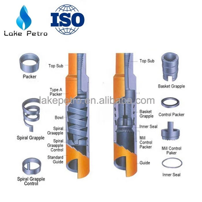
overshot assembly free sample

An OVERSHOT is attached to the end of a wireline and lowered into the outer tube. The Overshot then locks on to the Latch Head Assembly at the top of the core barrel.
The inner tube is then pulled to the surface with the core sample inside. Givens International offers an overshot for a spear point or quad latch head.

The present invention relates to an overshot tool having means for engaging and disengaging a latch in a core barrel head assembly used in core drilling operations and in particular although not exclusively to an overshot tool having an automated latching control mechanism to allow automated coupling and retrieval of the head assembly from within a bore hole. BACKGROUND ART
Diamond core drilling utilises an annular drill bit connected to a core barrel assembly. The core barrel is attached to the end of a number of tubular drill rods connected to form a drill string. The drilling progressively removes cylindrical cores of rock or material through which the drill and drill tube advance using a sequence of runs. This type of drilling utilises an inner tube assembly which has an inner tube connected to a head assembly to receive the core sample. The head assembly comprises a latch body connected to a valve housing which in turn is connected to a bearing housing which in turn is connected to an inner tube connector. The inner tube assembly connects to the inner tube connector and may comprise an inner tube, core lifter and core lift case. The inner tube assembly locates within a core barrel which comprises a combination of drill bit, reamer, outer tube, landing ring and locking coupling. The inner tube assembly can be retrieved from the surface when the inner tube is full. Empty inner tube assemblies can be delivered from the surface to the bottom of the drill string in order to recommence drilling.
The drill bit is advanced by rotating the drill string while applying downward pressure. In addition, drilling fluid such as water or drilling muds are pumped through the centre of the drill string, past the inner tube assembly and through the end of the drill bit in order to carry cuttings and other drilling debris to the surface via the annulus between the wall of the hole and the external surface of the drill string.
Of course, in the case of horizontal or near horizontal holes, it is likely that drilling fluid would naturally drain away particularly when the inner tube assembly is being retrieved or after the inner tube assembly is pumped back into the end of the drill string.
With either locating an inner tube assembly within a drill string or retrieving an inner tube assembly, when the inner tube is full, it is most often the case that an overshot tool is used to either lower the inner tube assembly into place, be used to pump the inner tube assembly into place or be lowered by itself to retrieve the inner tube assembly. In the case of a dry hole, the overshot tool will hold the inner tube assembly and their combined weight will allow the inner tube assembly to be lowered into position. In the case of a wet hole, or where the hole is partially wet or where the hole is horizontal, inclined upwardly or upwardly vertical, then the overshot tool has a sealing section which is fluid tight and enables fluid pressure to push the overshot tool and the attached inner tube assembly along the drill tubing.
The overshot tool, when used to retrieve an inner tube assembly when the inner tube assembly is full, can either fall under gravity to latch with the core barrel assembly or again be pumped into place to latch with the core barrel assembly.
A conventional latch in an inner tube assembly of a smaller diameter comprises a pair of pivoted and opposed arms. The lower portions below the pivot point of the arms have a resilient or biasing means which draw the lower ends together. This in turn causes the upper ends of the latch members to project outwardly from the inner tube assembly. In this position they can engage with a locking coupling included in the core barrel to latch the inner tube assembly with respect to the core barrel.
The overshot tool needs to cooperate with this latch so that the inner tube assembly can be held with respect to the overshot tool when it is being placed into position within the drill string and core barrel or alternatively must cooperate with the latch when the overshot tool is being used to retrieve the inner tube assembly.
In the case of retrieval, the overshot tool needs to engage the latch so that it releases the inner core assembly from the core barrel while at the same time the latch also needs to engage the overshot tool so that the overshot tool is held by the core barrel latch which allows for withdrawal of the inner tube assembly from the drill tube.
Various means exist for performing all of the above functions. However, it is the case that there are a number of different pieces of equipment that are used depending on the type of hole being drilled. The hole may be wet or dry and it may be vertically down or vertically up or any inclination in between. This means that the set of equipment, being the inner tube assembly and overshot tools differ in their configuration and operation depending on the type of hole being drilled.
It is an objective of the present invention to provide an overshot tool configured to cooperate with a latch mechanism of a head assembly via an automatic coupling/decoupling engagement such that the tool may be coupled to the head assembly and both components retrieved from the borehole quickly, conveniently and reliably. It is a further specific objective to provide an arrangement that provides both automated and manual decoupling of the tool from the head assembly to allow detachment by personnel at the surface and decoupling down the hole when the overshot tool is used to deliver the head assembly into the final latched position at the cutting end of the core barrel apparatus.
It is a further specific objective to provide an overshot tool that is sensitive to the method of delivery down the borehole so as to provide a feedback signal to an operator that the tool has reached its desired destination at the head assembly. It is a further specific objective to provide an overshot tool that is resistant to decoupling from the head assembly when used to deliver the head assembly into position should the assembly encounter obstructions during delivery.
The automated coupling and decoupling function of the present overshot tool is provided by primary and secondary engaging portions where at least one of the engaging portions is controlled by a latch control that is responsive to the environment in which the tool is placed and additionally the forces acting on the tool. Accordingly, the latch control is configured to control an axial and optionally a rotational movement of the primary and secondary engaging portions. The coupling and decoupling is achieved specifically via engagement by the primary engaging portion (to provide coupling) and the secondary engaging portion (to provide decoupling). The specific activation of the secondary engaging portion is controlled by the latch control and is responsive to forces acting on the tool at the cutting end of the borehole where the head assembly is maintained or released at its latched position against the inner surface of the core barrel. Additionally, the specific objectives are achieved by providing a latch control that is conveniently implemented as a pin and slot arrangement acted on by a bias member that is configured to provide from either an axially forward or rearward end.
According to a first aspect of the present invention there is provided an overshot tool for releasable connection to a head assembly of a core barrel drilling apparatus, the tool comprising: a primary engaging portion to engage a latch of a head assembly to provide an axial couple between the tool and the head assembly; a secondary engaging portion to temporarily engage the latch in addition to the engagement of the latch by the primary engaging portion; a retainer acting between the primary engaging portion and the secondary engaging portion; a housing having a region for engagement by the retainer, the primary engaging portion and the secondary engaging portion axially movable relative to the housing, the retainer configured i) to engage a first part of the region to releasably couple the primary and secondary engaging portions for combined axial movement and ii) to engage a second part of the region to allow at least partial independent axial movement of the secondary engaging portion relative to the primary engaging portion; a bias member acting between the housing and the secondary engaging portion to bias the secondary engaging portion axially relative to the primary engaging portion; wherein by adjustment of a position of the retainer between the first part and the second part of the housing the tool is adjustable between a first mode to allow axial coupling between the tool and the head assembly and a second mode to provide a decoupling of the tool from the head assembly.
Preferably, the primary engaging portion comprises an elongate shaft and the secondary engaging portion comprises a sleeve positioned around the shaft, the sleeve configured to slide axially over the shaft. The elongate shaft comprises an axially forwardmost end that represents an axially forwardmost part of the tool and is configured specifically to engage the latch of the head assembly.
Optionally, the tool further comprises a temporary rotational lock having at least two locking positions to temporarily lock the housing at the cover member at two rotational positions. The rotational lock is configured to provide quantised default positions of the secondary engaging portion relative to the housing and the primary engaging portion. Accordingly, a degree of force is required to adjust the releasable lock between the two positions so as to change the state of the tool to be configured for latching or unlatching of the head assembly. Such force may be provided by the pressure of a supply fluid or the weight of a free fall delivery assembly acting on the overshot tool.
Preferably, the retainer is fixed to and projects radially from the shaft and through the slot in the housing wherein the bias member is configured to force rotational and axial movement of the retainer within the slot. Accordingly, the retainer forms a radially extending region of the shaft such that rotational and axial adjustment of the retainer provides a corresponding movement of the shaft relative to the other components of the tool. The relative position of the shaft is therefore determined by the relative position of the retainer within the various slots and channels of the present overshot tool.
Optionally, an engaging end of the primary engaging portion comprises a bayonet configuration at a leading end of the tool being engagable with the latch; and an engaging end of the secondary engaging portion comprises a bell portion to engage the bayonet configuration in touching or near touching contact and release the bayonet configuration from engagement with the latch. Such an arrangement is advantageous to engage a particular configuration of latch at the head assembly that may comprise resiliently biases latching arms having engaging ends movable radially inward and outward.
Preferably, the housing of the tool comprises a coupling portion at a trailing end of the tool to mate with a valve housing or a free fall overshot attachment, the coupling portion capable of sliding axially within the housing and independently of an axial movement of the primary engaging portion. The present tool therefore is configured to mate with an overshot attachment or a valve housing to allow the tool to be both delivered and extracted from the borehole when coupled or decoupled from the head assembly. The latch control of the tool is configured to be sensitive to the coupling state of the valve housing or overshot attachment at the tool to both provide a feedback signal to an operator at surface level and to change the coupling state of the tool to either couple or decouple at the head assembly.
According to a second aspect of the present invention there is provided a method of core drilling using a tool forming part of a core barrel drilling apparatus, the method comprising: transporting an overshot tool in an axially forward direction through a core barrel apparatus; engaging a latch of a head assembly via a primary engaging portion of the tool to decouple the head assembly from fixed axial position at the core barrel apparatus and to axially couple the tool to the head assembly; transporting the coupled tool and the head assembly in an axially rearward direction through the core barrel apparatus to retrieve the head assembly, wherein the tool comprises: a primary engaging portion to engage the latch of the head assembly to provide the axial couple between the tool and the head assembly; a second engaging portion to temporarily engage the latch in addition to the engagement of the latch by the primary engaging portion; a retainer acting between the primary engaging portion and the secondary engaging portion; a housing having a region for engagement by the retainer, the primary engaging portion and the secondary engaging portion axially movable relative to the housing and the retainer configured to engage a first part of the region to releasably couple the primary and secondary engaging portions for combined axial movement and the retainer configured to engage a second part of the region to allow at least partial independent axial movement of the secondary engaging portion relative to the primary engaging portion; a bias member acting between the housing and the secondary engaging portion to bias the secondary engaging portion axially relative to the primary engaging portion; wherein by adjustment of a position of the retainer between the first part and the second part of the housing the tool is adjustable between a first mode to allow axial coupling between the tool and the head assembly and a second mode to provide a decoupling of the tool from the head assembly.
Optionally, the method may further comprise a release of the axial couple between the tool and the head assembly by moving axially the secondary engaging portion to contact the latch and releasing engagement between the primary engaging portion and the latch.
In one embodiment, the overshot tool has a first means for engaging a latch in a head assembly, the latch locking to the first means when engaged, and latch control means associated with the first means which is movable with respect of the first means wherein, in a first position, the latch control means allows the first means to engage the latch, and in a second position, the latch control means opens the latch to release the first means from the latch.
The first means on the overshot tool may comprise a number of different arrangements for connecting to the latch in the head assembly. Preferably the first means may comprise a spike which locates into and engages with the latch in the head assembly. Other arrangements may be suited to the first means and will depend on the type of latch used in the head assembly. For the sake of clarity, the first means will be described in the remainder of the specification as comprising a spike, however it will be realised that the invention is not to be restricted to this particular feature.
The latch may comprise a conventional dual arm latch where each arm is diametrically opposed to the other and pivotally secured with respect to the head assembly. However, other latch arrangements such as three of more latch arms or an alternative style of latch would be equally suited to this invention. For example, 4 or 6 arms may be used with larger diameter drilling systems.
In preference, the latch comprises at least two opposed and pivoted latch arms having inner ends that are biased towards one another to push the upper ends outwardly to abut with a locking coupling in a core barrel. The biasing means may comprise an elastomeric member located around the inner ends of the latch arms which acts to draw them together. This in turn causes the outer ends to pivot outwardly with respect to the head assembly.
The spike preferably has a tip that is shaped to that it will pass through the centre of the latch assembly so that the latch moves to allow the tip portion to pass through and, once the tip portion has passed the ends of the latch, the latch arms then closed behind the tip portion to thereby retainably engage the spike. In this position, with the latch engaged on the spike, the upper ends of the latch arms are withdrawn inwardly towards the head assembly so that they will disengage from the locking coupling and allow the inner tube assembly to move within the drill tube. This therefore allows the overshot tool to either retrieve an inner tube assembly by unlocking the latch from the locking coupling or lower the inner tube assembly into the drill tube by having the upper ends of the latch arms withdrawn from their latching position.
There will be a number of different circumstances where the spike is to be disengaged from the latch. It will need to occur at the surface when the inner tube assembly is manually removed from the end of the drill tubing or it will need to occur remotely once the inner tube assembly has landed at the end of the drilling tube which is known as a dry release. It may also need to occur when the inner tube assembly is part way into the hole.
In all cases, the latch control means operates to disengage the latch from the spike to thereby allow separation of the overshot tool from the inner tube assembly. In the case of when the overshot tool is delivering the inner tube assembly to the end of the drill string, this must be achieved remotely and at the surface, the manual disengagement must allow for easy and safe disengagement.
Preferably, the movement of the latch control means can be initiated remotely from the surface. When the overshot tool is returned to the surface it can be operated manually in a manner that is quick and convenient for an operator and does not involve any potential for injury to be caused or for any loss of or damage to the inner tube assembly.
The latch control means may have an arrangement that allows manual positioning at the surface to control movement of the latch control means. This may comprise a retainer which moves within the control slot to control movement of the latch control means in a predetermined way. For example, this allows for remote release of the latch control means so that it can move to a second position where the spike is disengaged from the latch in the head assembly.
Movement of the latch control means may be under the influence of a spring member that provides at least a compressive load to the latch control means. Movement of the latch control means may be further controlled by a retainer that can be moved to a released position to thereby allow the latch control means to move along the spike to a position where it will release the latch. The retainer can be designed so that it can be selectively released either once the inner tube assembly is located at the end of the drill string to provide remote release or when the inner tube assembly is retrieved to the top of the drill tube.
FIGS. 6aand 6bshow cross-section views of an overshot tool and valve housing and show the overshot tool releasing from the latches of an inner tube assembly,
FIGS. 10aand 10bshow cross-section views of an overshot tool and valve housing assembly engaged with an inner tube assembly to locate the inner tube assembly in a drill string,
FIGS. 12aand 12bshow the overshot tool connected to an inner tube assembly in preparation for delivery of the inner tube assembly to the core barrel of a drill string,
FIG. 13cshows a part view of the release mechanism part way through the operation of the release mechanism, and FIGS. 13aand 13bshow the overshot tool as it relates to the position of the release member shown in FIG. 13c, and
FIG. 14cshows the release mechanism in the position where the overshot tool is released from the core barrel head and FIGS. 14aand 14bshow the overshot tool as it relates to the position of the release member shown in FIG. 14c. DETAILED DESCRIPTION OF PREFERRED EMBODIMENT OF THE INVENTION
FIG. 1 shows an overshot assembly which is an assembly of an overshot tool 10 and valve housing 11. The overshot tool 10 is used to retrieve an inner tube assembly. It can also be used to deliver an inner tube assembly to the end of a drill string. The valve housing 11 can be used to pump the overshot tool 10 through a drill string. This will normally be to retrieve the inner tube assembly. The valve housing 11 is provided with seals 12 which provide flexible fluid seals between the valve housing 11 and the inner wall of the drill tube. An indicator valve 13 is provided within the valve housing 11 to provide an indication to the driller when movement of the valve housing 11 ceases. The indicator valve 13 is shown in FIG. 1 in its open position and comprises a ball 14 and fluid flow ports 15. In its open position, the indicator valve allows fluid that is pumped in behind the valve housing 11 to flow through opening 16 and the fluid flow ports 15. In its closed position and in order to pump the valve housing 11 along drill tubing, the ball 14 is set behind valve seat 17 which prevents fluid flow through the valve housing 11 and therefore enables fluid pressure to move the valve housing 11 along the drill tube (as shown in FIG. 3a).
Upon the valve housing 11 becoming stationary as would be the case when the overshot tool 10 engages an inner tube assembly, an increase in fluid pressure will cause the ball 14 to move through the valve seat 17 from the position of FIG. 3ato its position of FIG. 1 so that the fluid ports 15 are now open and allow fluid to freely flow forward of the valve housing 11 and around the overshot tool 10. This change in pressure provides an indication at the surface to the drill operator that the overshot tool 10 has landed. The valve housing 11 has a wire rope connector 18 to which a retrieval wire rope is secured. This enables the overshot tool 10 and valve housing 11 combination to withdraw an inner tube assembly from the drill hole. The valve housing 11 is secured to the overshot tool 10 either threadably or by a pin or both. The overshot tool 10 comprises a spike 20 and a latch control means 21. The latch control means 21 has an axial bore through which a portion of the shaft of the spike 20 locates. The spike 20 and latch control means 21 are located within a housing 22 and the housing 22 is in turn located within a cover member 23.
A spring 32 is connected to both the housing 22 and the latch control means 21. It provides both a compressive and torsional force to the latch control means 21. The spring 32 is compressed and normally provides a force that pushes the latch control means 21 away from the housing 22. The spike 20 has a tip 35 that comprises a conical portion 36 and a circumferential ledge 37. The conical portion 36 and ledge 37 are designed to engage with the latch in the inner tube assembly.
The spike 20 is journalled for sliding movement within a bearing 39 in the housing 22. The spike 20 is retained within the housing 22 via a pair of bolts 40 that threadably engage the end of the spike 20. The heads of the bolts 40 are located within slots 41 which in turn allows a small amount of longitudinal movement of the spike 20 with respect to the housing 22. When the end 25 of the retainer 24 is located within the circumferential slot 27 on the shaft of the spike 20 then the spring 32 acting on the latch control means 21 will in turn bias the spike 20 into its forward position shown in FIG. 2. When the end 25 of the retainer 24 is located within the longitudinal slot 26 on the spike 20, the spring 32 will push the latch control means 21 forward so that the bell portion 43 locates over the head portion 44 of the spike 20. The latch control means 21 has an abutment collar 45 which cooperates with the latch in the head assembly and its operation is described below.
Figure groups 4 to 7 show the engagement of the overshot tool 10 with an inner tube assembly. The Figures show a head assembly 47 and do not include the inner tube in which the sample is collected. The inner tube is threadably connected to an end of the head assembly 47. The head assembly 47 combined with the inner tube is referred to as the inner tube assembly.
FIGS. 4aand 4bshow the overshot tool 10 that has been pumped into a hole and has just engaged with the latches 48 of the head assembly. The latches 48 comprise a pair of arms 49 that are pivotally connected to the head assembly 47 via pivots 50. The inner ends 51 of the latch arms 49 locate behind the ledge 37 on the spike 20. An elastomeric o-ring 52 locates around the inner ends 51 and bias the inner ends 51 so that they engage against the head portion 44 of the spike 20. This holds the inner ends against the ledge 37 to thereby hold the latch 48 in a closed position with respect to the spike 20. The arms 49 have upper ends 53 which abut with the locking coupling of a drill string (not drawn) to hold the head assembly 47, in its drilling position where it is positioned to receive core sample as drilling progresses. In order for the upper ends 53 of the latch 48 to engage with locking coupling in the core barrel, the upper ends 53 need to project radially outward to a greater extent than what is shown in FIG. 4b. The diameter of the head portion 44 of the spike 20 is sized so that the inner end 51 are pushed outwardly against the O ring 52 to thereby retract the upper ends 53 to the position shown in FIG. 4b. This retracted position of the upper ends 53 provides clearance both with respect to the locking coupling and the inner wall of the drill tubing.
The example shown in FIGS. 4a, 4b, 4c, 5a, 5b, 5cand 5dare where the overshot tool 10 is required to be pumped into position which may be the case in respect of a wet hole where a column of water is maintained within the drill tube. It may also be the case in respect of a horizontal or upwardly inclined hole. Generally, it is required in a hole that is not sufficiently vertical (in the downward direction) to allow free fall of the inner tube assembly and associated overshot assembly.
FIG. 4cillustrates the setting of the cover member 23 for retrieval. FIGS. 4aand 4bshow the overshot tool 10 just as it connects to the head assembly 47 that is to be retrieved. The tip 35 of the spike 20 pushes through the inner ends 51 of the arms 49 to thereby unlatch the head assembly 47 from the locking coupling of the core barrel. The latch 48 is now engaged with the spike 20 with the inner ends 51 of the arms 49 located behind the ledge 37.
Prior to sending the overshot tool 10 into the drill tube to retrieve the head assembly 47 the latch control means 21 is positioned with respect to the housing 22 so that the retainer 24 is in the position shown in FIG. 4c. In addition, the cover member 23 is rotated so that a slot 61 in the cover member 23 is not aligned with the slot 60 of the control slot 29. This is a pre-loaded position so that the spring 32 holds the retainer 24 in this position. When the spike 20 engages with the latch 48 the fluid pressure continues to act on the valve housing 11 and there is simultaneous operation of both the indicator valve 13 and the retainer 24 associated with the latch control means 21. Both of these things occur substantially simultaneously.
In the case of the indicator valve 13, the pressure will be sufficient to force the ball 14 through the valve seat 17 to the position shown in 4a, 3band 3c. The valve seat 17 is a polymer and is sufficiently resilient to enable movement of the ball 14 at a predetermined pressure. This release of the ball 14 opens the fluid ports 15 which will enable fluid to flow through the valve housing 11. The valve arrangements within the head assembly 47 will be closed which will prevent fluid flow and allow the overshot tool 10 and valve housing 11 to be pumped through the drill string. Upon reaching a halt, the ball 14 moves through the valve seat 17 and causes a momentary pressure spike which provides an indication to the operator at the surface that the overshot tool 10 has landed.
At the same time, the spike in fluid pressure results in the valve housing 11 pushing the housing 22 and cover member 23 forward towards the head assembly 47 so that the housing 22 is caused to move in relation to both the latch control means 21 and spike 20. Engagement of the end 25 of the retainer 24 within the circumferential slot 27 results in the spike 20 and latch control means 21 moving rearwardly as is shown in FIG. 5d. This in turn causes the spring 32 to be compressed and for the retainer 24 to be moved rearwardly in relation to the control slot 29. It reaches the end of edge end 55 of the control slot 29 and the torsional force exerted by spring 32 causes the latch control means 21 to rotate so that retainer 24 moves into slot portion 60. This is illustrated in FIG. 5dwhere the latch control means 21 is now able to move longitudinally with respect of spike 20 as a result of the end 25 now engaging the longitudinal slot 26. This moves the latch control means 21 to the positions shown in FIG. 5bwhere the abutment collar 45 blocks any further inward movement of the upper ends 53 of the latch arms 49. This is the intermediate position of the latch control means 21 and physically prevents any movement of the outer ends of the latch 53 inwardly and thereby prevents any disengagement of the inner ends 51 of the latch arms 49 from the tip 35 of the spike 20.
The release of the indicator valve 13 provides an indication to the driller at the surface that the overshot tool 10 has engaged the head assembly 47. As the latch control means 21 will have operated automatically, then the combination of the overshot tool 10, valve housing 11 and inner tube assembly will be ready for removal. In order to release the overshot tool 10 from the head assembly 47 upon arrival of the combination of the overshot tool 10, valve housing 11 and inner tube assembly to the surface, the cover member 23 is rotated so that the slot 61 and the cover member 23 aligns with slot 60 in the housing 22. This results in spring 32 pushing the latch control means 21 fully forward to its second position where it disengages the spike 20 from the latch as previously described above. The rotation of the cover member 23 is illustrated in FIG. 6cand the release position is shown in FIGS. 6aand 6b.
This allows a very convenient and safe release of the overshot tool 10 from the head assembly 47. This release is illustrated progressively in FIGS. 7a, 7b, 7cand 7dwhere the bell portion 43 of the latch control means 21 locates over the head portion 44 of the spike 20 such that the end of the bell portion 43 abuts against the ledge 37. In this position, the outer surface of the bell portion 43 abuts against the inner surfaces of the latch arms 49 adjacent the inner ends 51 of the latch arms 49 so that the inner ends 51 move away from the head portion 44 and out of engagement with the ledge 37. Once the inner ends 51 of the arms 49 no longer engage the ledge 37 then as seen in FIGS. 7a, 7b, 7cand 7d, the overshot tool 10 can be withdrawn from the latch 48 and the end of the head assembly 47.
It may also be possible to use the overshot tool 10 and valve housing 11 to connect to an inner tube assembly at the surface and then pump this combination through the drill string. This is not necessary in general practice, but is possible with the overshot tool 10 connected to the head assembly 47 as shown in FIGS. 10aand 10bit would be possible to deliver an inner tube assembly to the end of the drill rods if required. The part conical portion 36 bears against a surface 54 within the head assembly 47. This enables the overshot tool 10 to push against the head assembly 47 while the latch 48 prevents release of the overshot tool 10. In this position, the overshot tool 10 combined with the valve housing 11 could be used to pump the inner tube assembly into the end of the drill string. This is generally not required, as the inner tube assembly itself would normally, in certain types of holes, be pumped into the drilling position. But as explained below, this invention is capable of being used in this way.
In this configuration, the combination of the inner tube assembly, overshot tool and valve housing 11 can be inserted within the upper end of the drill tube and then pumped into place. In this case a stuffing box is located on the end of the drill tube which enables fluid to be pumped into the drill tube behind the valve housing 11. The stuffing box is designed to allow a wire rope connected to the wire rope connector 18 to be fed into the drill tube as the combination advances to the end of the drill tube.
The combination will eventually reach the position where the inner tube assembly will latch into its drilling position. Once the inner tube assembly stops moving, the fluid pressure behind the valve housing 11 will increase and exert pressure which will result in both operation of the indicator valve 13 in the valve housing 11 and forward movement of the housing 22 with respect to the spike 20. Both of these operations occur substantially simultaneously.
Once in the slot portion 60, the compressive force applied by spring 32 pushes the latch control means 21 forward and as the end 25 of the retainer 24 is in the longitudinal slot 26 and the head 30 locates within slot 61 of the cover member 23, then the latch control means 21 moves from its first position as shown in FIGS. 10aand 10bto a second position where the latch control means 21 acts to open the latch 48 to thereby release the spike 20 as previously described and with reference to FIGS. 7a, 7b, 7cand 7d. The overshot tool 10 and valve housing 11 are then free to be returned to the surface by winching in the wire which is connected to the wire rope connector 18. The core barrel assembly is now latched in position where the upper ends 53 of the arms 49 are now engaged with the locking coupling and thereby latch the inner tube assembly into place. With the overshot tool 10 released from the latch 48, then it is free to be returned to the surface.
The overshot tool 10 may also be used for lowering an inner tube assembly into a dry hole where there is no fluid within the length of the drill tube or where the drill tube may only be partially filled. In this case, instead of using a valve housing 11 a free fall attachment 65 is connected to the overshot tool 10. This is illustrated in FIG. 11. The free fall attachment 65 has a series of guide rollers 66 that assist movement of the combination through the drill tube. Importantly, the weight of the free fall attachment 65 is sufficient to compress the spring 32. Accordingly, when the inner tube assembly latches in place, the weight of the free fall attachment 65 will cause movement of the housing 22 and cover member 23 with respect to the latch control means 21 and spike 20. However, while the combination of the free fall attachment 65, overshot tool 10 and inner tube assembly is suspended from the winch wire (attached to wire rope connector 18) there will be no relative movement between the housing 22 and the latch control means 21.
Prior to inserting the inner tube assembly into the drill tube, the position of the latch control means 21 is pre-set to the extreme end of the control slot 29 as shown in FIG. 12c. This position provides a degree of safety as it will require two separate operations to release the overshot tool 10 from the head assembly 47. This prevents accidental release of the overshot tool 10 in the case where the progress of the inner tube assembly through the drill tube is interrupted. Clearance between the landing seal 56 and the inner surface of the drill tube is not great and all that may be required to jam the progress of the inner tube assembly would be some deposits on the inner surface of the drill tube or some damage to the inner surface of the drill tube. If this occurs, then the full weight of the free fall attachment 65 will be applied to the overshot tool 10 which will result in the latch control means 21 indexing through the first section of the control slot 29. The first application of the weight of the free fall attachment 65 will result in the housing 22 moving downwardly which in turn results in the retainer 24 moving to end 67 of the control slot 29 as seen in FIG. 12c. Once in this position, the torsional force applied by spring 32 will result in the latch control means 21 rotating and bearing against end 67 of the control slot 29 as seen in FIG. 12c. Once the cessation of movement of the inner core assembly is sensed at the surface, the cable is winched in and the weight of the free fall attachment 65 is removed from the overshot tool 10. However, the retainer 24 goes to the position shown in FIG. 4cand the overshot tool 10 is not released from the head assembly 47. This then allows the driller to again lower the core barrel assembly in attempt to bypass the obstruction. If it does bypass the obstruction, then it can continue to its landing position at the end of the drill rods. However, if it again jams, then the weight of the free fall attachment 65 will act to release the overshot tool 10 from connection to the head assembly 47. In this case at least the overshot tool 10 and free fall attachment 65 can be recovered and then an attempt can be made to retrieve the inner tube assembly.
It is also possible that the inner tube assembly may be released from the overshot tool upon reaching water in a partially water filled hole. As the inner tube assembly with the attached overshot tool and free fall attachment 65 are lowered into the water, the movement of all of these components will be impeded. This will be sensed at the surface by the winch cable becoming slack.
At the same time, the weight of the free fall attachment 65 and overshot tool will operate the latch control by indexing it through the first section of the control slot 29. The inner tube assembly could now be released by a further tensioning of the cable and a subsequent release of the cable which in turn will result in the weight of the overshot tool 10 and free fall attachment 65 which will then result in release of the overshot tool from the inner tube assembly. The inner tube assembly will then be free to float to its latched position within the core barrel and while this is occurring, which will take some time, the operator can retrieve the overshot tool 10 by winching it out of the hole. This will obviously save some time as the overshot tool 10 may be out of the drill tube by the time the inner tube assembly latches into the core barrel.
In a fully dry hole, the inner tube assembly will latch into drilling position with the latch control means 21 and retainer 24 in the position shown in FIG. 12c. Once in this position, then it will be necessary for the driller to lift the free fall attachment 65 and overshot tool 10 twice in order to release the overshot tool 10 from the latch 48 as the process of attachment will have resulted in the weight of the overshot tool 10 and free fall attachment 65 already indexing the retainer once as shown in FIG. 13c. This release is illustrated progressively in FIGS. 13a, 13band 13cwhere FIG. 13cshows the retainer 24 located at the end of both slot 60 and 61 which results in the latch control means 21 moving to its second position as shown in FIG. 13bwhere it releases the overshot tool from the head assembly 47. This then allows the overshot tool 10 and free fall attachment 65 to be retrieved to the surface.
The free fall attachment 65 combined with the overshot tool 10 can also be used to lower an inner core assembly fully into a hole which is partially wet. In this case, the combination of the overshot tool 10, free fall attachment 65 and inner tube assembly will be lowered via the winch cable until the combination contacts the water within the drill tube. At this point, movement of the combination may be retarded by the water however it will still continue to fall under its own weight with the overshot tool 10 and free fall attachment 65 connected. Similarly, the weight of the free fall attachment 65 will be sufficient to operate the latch control means 21 and retainer 24 in the matter described above when the inner tube assembly reaches the core barrel.
As will be appreciated from the above description, the invention provides useful means of controlling the operation of an overshot tool 10 to both retrieve and deliver an inner tube assembly into and out of a core barrel. Further, the set of tools described above can be used both in relation to wet and dry holes and can also be used either in relation to pumping in or lowering under gravity.
Overshots are a key component of wireline coring systems. To retrieve the core sample, the overshot is lowered into the hole on a wire cable until it comes in contact with the spearhead point on the head assembly. Positive latching lifting dogs securely attach, and the inner tube assembly is pulled from the hole to retrieve the core. V-lock Overshots Hole Products" V-lock overshots are safe, reliable, fast, and easy to use. The automatic safety feature is designed to reduce the chance of an accidental release. When the inner tube assembly is attached and lifted, the lifting dogs automatically retract into position. No extra manual steps are required to activate the safety feature, thus reducing the potential for human error. Standard Overshots Hole Products" standard overshots feature a manual safety lock pin. Once the core filled inner tube is hoisted above the top of the drill rods the safety lock pin can be inserted through the overshot head and under the spearhead point. This will allow the operator to hoist and remove the core sample from the inner tube.
The DiscovOre head assembly and the Arrow 3S auto-lock overshot combine to create a revolutionary new core barrel system that provides safety, speed and simplicity. The new design has eliminated the weak and potentially hazardous components of a standard core barrel, the spearhead and spring pins.
The DiscovOre head assembly and the Arrow 3S auto-lock overshot combine to create a revolutionary new core barrel system that provides safety, speed and simplicity. The new design has eliminated the weak and potentially hazardous components of a standard core barrel, the spearhead and spring pins.

Figure 2 is a vertical semiseetional drawing of the weighted coring device modification with the overshot assembly in position for obtaining a photographic record,
ReferringnowtoFigureLasurfacevessel III is shown from which submarine coring device I l is suspended by means of cable II. Connection II is made by means of which a sufficient quantity of submarine overburden it is hydraulically removed from formation II from which it is desired to obtain a core sample as hereinafter more fully described in conjunction with Figure 5. Waterispumpedbymeansofapump aboard vessel It through connection It in order to accomplish the overburden removal, thereby exposing the upper surface of submarine formation ll. Subsequently percussion means It is actuated via connection II from a power source aboard vessel II and which percussively drives core sampling tube It via iar rod ll into submarine formation It thereby enclosing a core sample thereof within tube It. Once the sampling tube is driven a sui"dcient distance into formation II to obtain the desired sample, the inclination and azimuth of the device is recorded by a recorder attached to the overshot assembly, andthecombineddeviceishauledtothesurface via suspension cable II. The core sample isremovedfromthecorebarrel llandthephoto- 4 graphic record of the inclination is removed from the overshot assembly briefly described above.
In the obtaining of core samples by employing the weighted modification of this device, suspension cable I 2 lowers the device to a distance above the bottom from which the sample is to be obtained and upon release of the suspension the device is allowed to fall to and to penetrate the submarine formation thereby filling the core sampling barrel with a sample of the submarine formation. While the device is in a position assumed on penetration of the formation, the overshot assembly is lowered to engage the coring device and a record is made of the inclination and azimuth of the inclination of the device. The device and the recovered core sample are subsequently brought to the surface and the sample and the record removed from the coring device.
The core sample following the impact is enclosed within core barrel 2| and the entire device extends upwardly into the body of water from the submarine formation at a certain angle of inclination usually less than 5". overshot assembly II to which recorder case 3| is integrally attached is lowered to engage upper sampling tube 20 and to assume a predetermined orientation with respect thereto. overshot assembly 88 is hinged to permit being closed around suspension line I! and is lowered by means of suspension line II. The assembly comprises a hinged cylindrical section cut 06 at an angle to its longitudinal axis exposing elliptical surface It. Positioning lug I1 is integrally attached to upper sampling tube II and as the overshot assembly slides down around the upper end of upper sampling tube 2|, overshot assembly turns so that lug I1 is engaged by slot 38 as shown in Figure 4. The position of overshot assembly 38 with respect to the sampling device penetrating a submarine formation is thereby always maintained at a known orientation which is predetermined by positioning lug 31 and slot Ill. By these means recorder case 34 assumes the same angle of inclination and orientation as the core sampling device since no rotary motion between the upper, lower and core receiving tubes is permitted. A photographic record therefore of the inclination and azimuth of recorder 34 directly determines the strike and dip of the core sample recovered from the formation. The recorder case 34 is then hauled to the surface and the coring device and core sample is pulled free from the formation. Weight 23 may be raised to cause a series of impacts between collar 28 and shoulder 29 to facilitate removal of the device from the formation.
Referring now to Figure 5. a second modification of the core sampling device of the present invention is shown in more detail and which is suspended by cable I! from a surface vessel and provided with recorder housing 34 supported on overshot assembly 33, substantially the same mechanism as was described in connection with Figures 2 and 3. This modification of the device consists of upper tube 4| to which cable I! is attached and with the upper end of which overshot assembly 33 engages. Upper tube 4| is integrally attached to percussion assembly housing 42 within which is supported a hydraulically, electrically or pneumatically operated percussive means which may be an electric or an air hammer of the well known type. Driving tube 43 extends from within hammer case assembly 42 through stufllng box 44 which provides a fluid tight seal to prevent entry of water into case 42. Driving tube 43 also extends through stuffing box 45 and through flushing head 46. Flushing head 46 is slidably mounted upon jar rods 41 which are provided with stops 48 and by means of which flushing head and flushing tube 49 may move longitudinally with respect to driving tube 43 and coring tube 50 attached thereto. Aperture Ella permits escape of water displaced from barrel 50 by the core sample. Flushing inlet Si is provided and flushing fluid hose 52 is connected therewith to introduce a fluidsuch as sea water or fresh water from the surface of the water body through flushing head 46 into the annular space between flushing tube 49 and sampling tube 50. As explained in connection with Figure 1 the purpose of this flushing fluid is to hydraulically wash away the submarine overburden comprising silt, soft sand, and the like, from the surface of the submarine formation from which the sample is desired. Sampling tube ill is provided with core cutting head or hit 21 and scribe 28, the same as in Figure 2. As the bit is percussively forced by the action of the hammer or percussive means within assembly case 42 into the formation, flushing tube 49 and flushing head 46 rest on the formation being penetrated and sampling tube 50,
when the core sampling tube III has penetrated the desired depth in the formation, actuation of the percussion means in case 42 is stopped and overshot assembly I! is passed down suspension cable l2 to engage the upper portion of upper sampling tube 4| in the manner described above. After the predetermined time interval has elapsed and the overshot assembly is in the position shown in Figure 5, a preset photographic exposure records the inclination and the azimuth of the inclination of the device as it rests prior to removing the device and the core sample from the formation. The device and the sample are then subsequently pulled free of the formation, aided if necessary by vibration generated by the percussion means, and hauled to the surface.
Referring now to Figure 6, a schematic cross sectional elevation view of instrument housing 34 shown in Figures 2 and 5 is shown. Housing 34 is provided with supports 55 by means of which it is integrally connected to overshot assembly 33. Within housing 34 is situated timing mechanism 56, electric switch 51, power supply means 58 which is conveniently an electric dry cell, camera recorder 59. electric lights Gil which are connected via electrical connections GI and 82 in parallel with switch 51 and power supply means 58, and chamber 53 provided with magnetic compass means 64, compensating magnets 63a and 64a, scribe mark 82a. and convex surface 65 which is translucent and provided on its assaoss upper surface with a series of inscribed circles which are concentric about center point II. When the overshot assembly is in position for recording, scribe mark tie is in a flxed known relationship with respect to scribe It on bit 21 so that a photographic record of the geographic orientation of scribe 20 is obtained. Chamber B3 is filled with a fluid leaving bubble 51 which rises to the highest point below convex surface 65 and indicates by its relation to the inscribed circles mentioned above the inclination of the instrument. A small float such as a hollow sphere weighing less than its displaced volume of the fluid may be used instead of a bubble and is preferable since it photographs better. Camera 58 photographlcally records at a predetermined time the position of bubble or float "1, the direction indicated by magnetic compass means 64, and the position relative to the compass of scribe marl: 82c thereby recording the inclination and the azimuth of the inclination of the core sample taken from a submarine formation.
* An inertia operated lever actuating the starting pin of a stop watch set to close switch 51 after a preset time is suitable. In this modification. overshot assembly 33 shown in Figure 2 is eliminated and recorder case It may be suspended in shock proof mountings within upper sampling tube 20 and aligned with respect to scribe 26. The device is provided with fluid proof couplings for recovery oi exposed him and insertion of new film. Thus the time necessary for lowering the overshot assembly to the device after formation penetration is saved.
Such a shock proof recording mechanism may be incorporated in the sampling device shown in Figure 5 where a power device percussion means is used to drive the sampling barrel It and coring bit 21 into the formation. In this modification the recording device is preferably operated from the surface whereby the lights for exposing the photographic record are lighted manually from the surface after the core barrel has penetrated the desired distance into the formation. In this instance an inertia-actuated time delay mechanism is not employed. Overshot assembly 33 is not used and recorder case It incorporated in a shock resistance mounting within upper sampling tube ll shown in Figure 5.
Referring to Figure 7, this modification of the core sampling device combines the single impact feature of the device shown in Figure 2 with the flushing tube shown in Figure 5. The device is lowered through the overburden which is hydraulically removed to a position adjacent to the formation to be sampled and the core barrel is dropped from a raised position within the casing. The impact drives the core barrel into the formation in the same way as that described in Figure 2. The present modification comprises outer casing HI suspended by cable I! and provided with flushing inlet II and connection I! through which flush fluid is passed to remove silt and overburden from the formation. Suspended within casing II is upper core sampling tube ll provided with guides 14, II and I6 by means of which smooth longitudinal motion of tube ll relative to casing II is permitted. Core barrel 25 provided with core head 21 is attached to sampling tube ll by means of connection ll. Aperture lid is provided whereby fluids displaced from core barrel II by the core sample during penetration may escape. The lower end of sampling tube II is provided with collar I! to which is attached retainer spring It. Spring 10 is sized to allow free passage therethrough of core barrel 2! and to engage connection II. Loss of sampling tube and core barrel from the bottom of casing II is hereby prevented. Sampling tube 13 is weighted with weights in chamber and the recording instruments may be placed in chamber lie and oriented with respect to the scribe in a known way. The recording instruments may be incorporated in the overshot assembly as described above if desired but in such a modification sampling tube 13 must be prevented from turning with respect to casing 10 by means of a keyway and key or spline or other means.
2. An apparatus for obtaining samples of submarine formations which comprises a hollow core barrel, 9. jar rod attached to said core barrel and extending through a lower sampling tube, a. massive weight concentrically attached to said lower sampling tube, an upper sampling tube attached to said lower sampling tube, radial guide fins attached to said upper sampling tube, a suspension line attached to the upper extremity of said upper sampling tube for suspending the entire device from the surface of a body of water, an overshot assembly containing means for recording the inclination and azimuth of inclination of said device. said device being allowed to 10 fall by gravity from a point above said subsurface formations and to penetrate the same.
12. An apparatus according to claim 11 in combination with an overshot assembly, means therein for recording the inclination and azimuth of the inclination of said apparatus, means for lowering said overshot assembly down said suspension means into engagement with said apparatus while said apparatus is penetrated into the formation sampled.
18. A method for surveying and sampling submarine formations which comprises lowering a core sampling assembly having a core receiving barrel from the surface on a suspension line, generating a percussive force below the surface of the body of water and within the thus suspended assembly by the impact of a movable weight accelerated by the force of gravity against said core receiving barrel, driving said core barrel percussively by means of said force into said formation thereby taking a core sample, subsequently combining said core sampling assembly while penetrating said formation with an inclination and azimuth measuring devices lowered along said suspension line, measuring the inclination and azimuth of the inclination of said tube while penetrating said formation, and removing said core sampling tube and said core sample from said formation.

In the past, core drills of this general type have been subject to certain disadvantages. One disadvantage has involved to use of complicated latch mechanisms to lock the removable core barrel assembly in operating position, whereby locking engagement or disengagement can occur automatically as the core barrel assembly is lowered into operating position or lifted by the wire line. These complicated latch mechanisms were subject to mechanical failure, breakage, erosion and wear due to drilling muds and the like.
It is an object of this invention to provide an improved wire line core barrel and it is an object to provide a core drill having a detachable retractable wire line core barrel with an improved simplified strengthened latching mechanism so as to prevent the core sample from pushing the core barrel upwardly through the drill stem and at the same time lock the portions of the core barrel in contact with the drill stemagainst rotation within the drill stem while allowing free relative rotation of the core receiving portion of the core barrel assembly.
Another diiliculty encountered in the past has been the tendency of the core barrel to cramp or bendwhere it is grasped by a grappling` tool when the grappling tool` core barrel assembly is withdrawn from the drill string at the surface. This is due to the pivoting allowed at the jaws of the grappling tool of prior devices. Occasionally in such prior devices, the entire core barrel would break loose and fall back to the bottom of the well, damaging both thecore barrel and the core sample.
It is another object of this"invention to provide a grappling tool or overshot assembly for retracting the loaded. core barrel through the drill string from the bottom of the well which is vprovided with means for stabilizing the core barrel and retracting assembly and substantially preventing cramping or bending movement between them. As the core barrel sample moves up into the core receiving tube of the core barrel inner tube assembly, the resultant forces cause the latching dogs of the assembly to become jammed so that they can be released only with difficulty. It is an object of the invention to provide an apparatus which obviates or reduces these diliculties. Y
It has also" sometimes occurred in the use of existing core barrel devices that for one reason or anothei the entire core barrel and grappling tool assembly becomes jammed at the bottom of the drill string but the operator working at the surface becomes apprised of this fact only when the wireline snaps and breaks. It then becomes necessary to withdraw the entire drill string in order to recover the core barrel andgrappling device and line.
Another object of this invention is to provide an overshot assembly which is part of this inventionv with a shearing pin coupling so `that in case of jamming of the core Vbarrel and grappling tool assembly .the pin will shear off rather than permitting the" wire line to4 break.
To the accomplishment of the foregoing and related ends, this invention then comprises the features hereinafter fully described and particularly pointed out in the claims, the following Figures l and 2, taken together, constitute a longitudinal sectional view of a core drill, core barrel inner tube as-I sembly, and overshot assembly embodying the present` invention, Figure 1 showing theupper portion and Figure" 2 showing the lower portion.
Figure 3 is an enlarged transverse sectional View ofthe hanging support means and fluid by-pass channels of the core barrel assembly taken along the line and in the direction of the arrows 3 3 of Figure 2.
Figure 4, is an enlarged transverse view, partly insection, of the latching andgrapplingportions of the core4 barrel assembly of this inventiontaken generally along description setting forth in` the line and in the direction of the arrows 4-4 of Figure l.
Figure 5 is a longitudinal sectional view of the latch andlocking means. taken along theline and in the direction of the arrows 5-5 of Figure l. Referringnow to the drawings and particularly to Figures land 2, there is here illustrated one embodiment of invention comprising generally, a hollow drill tube "made up of sections"of pipe or tubing screw threaded at their ends for coupling and having at their lower end abit-11. In -the art, the drill tubes, of which the lowermost end is shown in Figurel, are sometimes designated drill rod, drill string or drill stem. The term drill stem willV be used herein. The drill stem 10 is hollow and in it at its lower end is positioned a core barrel inner tube assembly generally designated 20, in which thecore isreceived. l
The lowermost section of the drill stem carries a"drill bit 11.and in the formhere illustrated is a so-called diamond core drill. -The cutting surfaces are formed by the annularA face 12 and sides 14 of the thickened bottom portionofthe bit which are formed of or surfaced with diamondsfembedded in a hard facing material. While the invention is illustrated by reference to a diamond core drill, itis to be understood, however, that the invention is not limitedthereto but on the contrary is applicableV to all types of hollow core bits such as are conventionally used in taking core samples. The drill bit portion 11 is threaded at 15 onto the reaming shell 21 which may have diamonds or other hard points on its outer surface. bit 11 has a widened bit face 12 having a maximum diameter 14 and inner (or minimum diameter) 16. An inner shoulder is formed at 17. The cuttingface 12 is provided with a central aperture or opening 1S through which the core sample, as it is cut, enters into the core barrel inner tube assembly indicated generally a-t 2i). The reaming shell 21 when provided on its outer surface with a cutting point such as diamonds embedded in a hard facing coatingserves to ream the hole to true diameter. The reaming shell is in turn mounted by screw threads on the outer tube 22 at the bottom of the drill stem. The core barrel inner tube assembly indicated generally at fits loosely within the outer tube 22 extending down to the drill bit 11, being provided with latch body shoulders 24 which face downwardly and are adapted to seat upon The an annular .internal shoulder 25 in a collar or hanger coupling 261 screwed onto upper end of the outer tube 22. The"lowercore-receiving end of the core barrel inner tube assembly 20is held" free from contact with the inner shoulder 17 of the drillbit.
The core barrel inner tube assembly 20 includes a latch body 44 (with its latches 55), latch release tube 66-69, and spindle 35,.cap 32, and core receiving tube 27", extension 28 therefor and all associated parts. The core receiving tube 27 has a replaceable core tube extension f 2 8 coupled to |its lower end and a core lifter 29 and a core lifter case 30 threaded onto the lowery end of the core tube extension 28. Case 30 holds the core lifter 29. The
core lifter 29 comprises a resilient split spring steel ringA having a plurality of longitudinal slots or ribs around its inner periphery which are adapted to grasp and hold the core sample, so as to break oi the core and then hold rt"from falling from the core barrel as the core barrel is being raised tothe surface. The lifter ring"29 is tapered on its" outerv surface and mates with the correspondingly tapered inner surface of core lifter case 3l). Hen


 8613371530291