
overshot assembly pricelist
Explore the various drilling overshot products available for wholesale at Alibaba.com. Get a drilling overshot for drilling water wells, water exploration holes, geological exploration, coal mines, and other kinds of mining. Some drilling overshot options use caterpillar tread to move. Others use rubber tires, while others require a separate means of transport. Caterpillar tread propulsion can climb up to 25 degrees inclination. Some products in the range are capable of drilling over 200 meters, while others are only used for open-pit mining with depths of around 3 meters. Drilling can be done vertically downwards, horizontally, or in a slanting direction. Drilling speed depends on the power of the machine and the general hardness of the surface. The hole diameter can vary from 90mm to 200mm.
drilling overshot options also include an air compressor, a mud pump, drilling rods of various sizes, connectors, and a drilling tower. Drilling is done using drill bits of various shapes, sizes, and compositions. You can choose between diamond bits, alloy ring-shaped bits, 3-wing alloy bits, PDC bits, and hammer bits. Each drill bit uses different drilling methods, including rotary, percussion, blast hole, and core drilling.
Smaller products have a lifting power of around 25 kilonewtons and weigh about 2,500kgs. They’re ideal for small-scale drillings such as farms and homes. Larger ones are faster with more power, making them ideal for commercial use. Browse through Alibaba.com and find a drilling overshot that’s ideal for your work scope. Buy mine drilling rigs for your wholesale business at competitive prices. Chinese wholesalers provide you with customization options and great after-sales services.
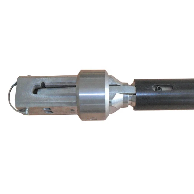
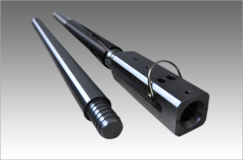
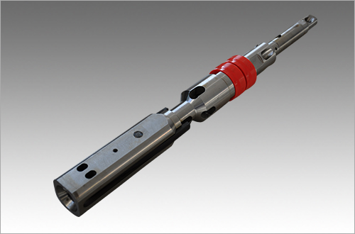
Overshots are a key component of wireline coring systems. To retrieve the core sample, the overshot is lowered into the hole on a wire cable until it comes in contact with the spearhead point on the head assembly. Positive latching lifting dogs securely attach, and the inner tube assembly is pulled from the hole to retrieve the core. V-lock Overshots Hole Products" V-lock overshots are safe, reliable, fast, and easy to use. The automatic safety feature is designed to reduce the chance of an accidental release. When the inner tube assembly is attached and lifted, the lifting dogs automatically retract into position. No extra manual steps are required to activate the safety feature, thus reducing the potential for human error. Standard Overshots Hole Products" standard overshots feature a manual safety lock pin. Once the core filled inner tube is hoisted above the top of the drill rods the safety lock pin can be inserted through the overshot head and under the spearhead point. This will allow the operator to hoist and remove the core sample from the inner tube.
* The above torque values are the maximum recommended torque values and are set at 50% of the calculated theoretical yield torque. These torques are not required for all fishing jobs and lower torque values will work with less wear and tear to the threads. It is assumed that the torque is applied evenly to the OD so as to not collapse the OD. The above tensile strengths are calculated theoretical tensile yield strengths and are considered accurate to ±20%. It should be noted that all strengths assume straight and steady pulling of a fully engaged round fish. Any tong marks, damage to the Bowl"s surface, or jarring can reduce the strength substantially. Makeup Torque w/ Bowl Tensile Yield w/ BowlO.D. in Part Numbers (ft-lbs)* (lbs)*Inches Assembly Top Sub Bowl Guide Top Sub Guide Top Sub Guide2 5/16 B8919 A8920 B8921 9404 600 80 78,800 9,5002 21/32 C10199 A10200 B10201 A10206 1,300 200 137,200 23,7003 1/8 9305 9311 9306 9312 2,000 400 191,200 34,4003 3/8 C4623 A5083 B5088 A5093 2,700 700 235,000 54,7003 5/8 C5080 A5081 B5082 A5087 2,700 900 218,700 71,9003 5/8 9270 9276 9271 9275 2,500 500 210,000 40,3003 3/4 37585 37586 37587 37592 2,600 500 208,500 42,0003 15/16 C5101 A5102 B5103 A3598 1,900 900 141,000 64,7003 7/8 C1835 A1842 B1836 A1841 2,400 800 195,600 55,4004 1/8 9105 9106 9107 1746 3,500 1,000 264,100 69,8003 7/8 21300 21301 21302 21307 1,700 400 137,600 27,8004 3/8 C4619 A4620 B4621 A4622 4,400 1,300 286,100 80,0004 9/16 C5151 A5152 B5153 A4341 5,500 1,600 347,400 97,5004 11/16 9109 9110 9111 6667 3,400 1,300 225,300 81,1004 5/8 C5129 B5130 B5131 A5135 5,700 1,200 361,600 73,3004 11/16 9120 9110 9121 9125 3,400 1,000 225,300 63,8004 7/8 C5154 A5155 B5156 A5161 6,200 1,100 368,000 67,6005 9/16 5896 5897 5898 187 9,000 2,600 496,900 137,0005 1/2 C4969 A4970 B4971 M1138 7,800 1,700 404,200 89,3005 5/8 5698 5699 5700 1143 7,100 1,700 370,800 91,2005 5/8 C5168 A5169 B5170 B2203 6,900 1,900 350,700 98,7005 3/4 8975 8976 8977 6121 8,100 1,600 414,400 84,4005 29/32 C5171 A5172 B5173 B4371 8,200 2,200 409,100 105,3006 1/8 7787 7789 7788 5946 9,000 2,400 425,700 119,4005 3/4 C11823 A11824 B11825 A11830 5,500 1,600 266,500 74,9006 3/8 6655 6656 4503 4504 10,400 3,400 473,400 151,7006 1/2 4773 4774 9205 4775 8,400 2,900 395,200 132,5006 5/8 8625 8626 8617 8621 9,500 3,300 415,800 141,7007 3/8 9692 9693 9694 9691 13,500 3,700 560,100 152,6007 5/8 8741 8742 1641 5525 16,000 4,700 619,500 187,5007 7/8 C2108 B2106 B2109 A2072 31,100 6,400 1,171,100 236,9007 5/8 9860 9861 9862 9867 12,100 4,000 485,600 158,4008 1/8 C5342 A5343 B3711 A2376 22,900 6,800 809,500 240,0007 3/4 4785 9133 9134 9139 13,200 4,200 521,300 161,3008 1/4 C3032 A3033 B3034 A1818 18,200 7,000 642,100 246,6007 7/8 C5222 A5223 B5224 A5229 11,300 4,400 409,200 159,2008 1/8 9217 9218 9219 9226 17,300 4,600 648,700 170,7008 3/8 C5354 A5355 B5356 A5361 14,500 5,200 496,800 175,6009 5/8 264 265 266 240 26,400 10,200 805,600 303,2009 1/2 4834 9063 9062 9059 20,300 6,200 649,500 197,20010 1/8 8960 8961 8962 8959 32,500 10,200 969,300 302,60010 5/8 C5321 A5322 B5323 A5328 37,200 13,100 1,009,900 350,40011 1/4 C12822 A12823 B12824 A12829 39,500 15,700 995,350 394,70011 3/4 5329 5330 5331 5336 52,200 16,100 1,277,400 387,60012 3/4 15800 15801 15802 15806 51,700 16,100 1,214,900 376,90013 3/4 33006 33007 33008 33012 70,500 17,600 1,541,100 385,30016 68028 68029 68030 68035 111,200 34,670 1,972,600 614,80016 3/4 64553 64554 64555 64560 107,500 26,670 1,932,900 479,700

A core barrel inner tube assembly that is propellable under fluid pressure to the bit end of a drill string and provide an open bypass channel for inward flow therethrough only after the latch has moved to its latch seated position.
In U.S. Pat. No. 3,120,283 to Braun there is disclosed a core barrel inner tube assembly having an overshot coupling portion retained in a position by the latches in their retracted position to prevent fluid bypass until the latches move to their seated position and thence under gravity or inward fluid pressure move to permit fluid bypass and prevent the latches moving to their retracted position until the coupling portion is retracted; and a fluidly propellable overshot assembly. Also it is old to provide a core barrel inner tube assembly that is similar to that of the second embodiment of U.S. Pat. No. 3,333,647 to Karich except that the spearpoint plug has an annular fluid seal member with a bypass channel that includes an outer port opening outwardly of the seal member and an inner port that is blocked by the latch release tube when the plug is in its inner position relative to the tube, and resilient means to urge the release tube inwardly relative to the latch body to the release position. The plug is mechanically forced to its bypass open position when the release tube moves inwardly.
U.S. Pat. No. 3,266,835 to Hall discloses a core barrel inner tube assembly fluidly propellable in any direction and includes a valve assembly connected to a spearhead and resiliently urged to a position to block fluid flow. When the inner tube assembly moves to its inner position, water pressure forces the spearhead assembly to move to open a bypass channel and allow the latches to move to a latch seated position. If the latches do not seat properly a valve is not opened and bypass is blocked. French Patent No. 2,014,485 discloses a first embodiment of a latch that has an axial outer hook portion for couplingly engaging an overshot assembly and an inner hook portion extending transversely in the opposite direction from that of the hook portion for coupling engaging a latch seat while the second embodiment has an outer hook portion for couplingly engaging an overshot assembly and an outer portion for engaging a latch seat, both of which are outwardly of the latch pivot. U.S. Pat. No. 3,701,389 to Egnelov et al also discloses some of the same structure as disclosed in the French patent. U.S. Pat. No. 1,427,268 to Dodd discloses outer latches to block outer movement of the core barrel inner tube assembly and inner latches to block inward movement when in the core collecting position.
A core barrel inner tube assembly that includes a latch body portion pivotally mounting a latch for movement between a retracted position and a latch seated position, an axially elongated portion extending axially relative to the latch body portion for defining a fluid bypass channel, valving mechanism extending within the channel that is movable between a first position substantially blocking inward flow through the channel and a second position providing a fully open fluid channel, valve control mechanism that is movable relative to the latch body and elongated portion for moving the valving mechanism from the valving mechanism second position after the latch has moved from its retracted position to its latch seated position with the assembly at the bit end of a drill string and inward fluid pressure has been significantly decreased from that previously applied. In one embodiment the valving mechanism is at least in part retained in its first position by the valve control moving mechanism which in turn is prevented from moving the valving mechanism by abutting against the latch in the latch retracted position. In another embodiment the valving mechanism and the elongated portion are of a construction that the valving mechanism is moved inwardly from a fluid channel open position to the valving mechanism blocking position by inward fluid flow when the bore hole extends upwardly in an inward direction. Advantageously the last mentioned embodiment has a latch with an overshot hooking portion and a foot on the opposite axial side of a latch pivot to extend transversely outwardly in the same direction with the foot being abuttable against the valve control mechanism to prevent the valve control mechanism moving the valving mechanism to its second position until the latch moves from its retracted position to the latch seated position.
One of the objects of this invention is to provide a new and novel core barrel inner tube assembly that requires its latch moving to its latch seated position and a substantial decrease of inward fluid pressure applied to the assembly before a fluid bypass channel fully opens for inward bypass fluid flow. In furtherance of the above object, it is another object of this invention to provide an assembly that is fluidly propellable inwardly regardless of the direction of extension of the bore hole. Another object of this invention is to provide in a core barrel assembly new and novel means for blocking inward fluid bypass until the assembly latch means moves to its latch seated position and retains the latch means in the latch means seated position until the assembly is retracted by an overshot device.
A different object of this invention is to provide new and novel positive latch means in a core barrel inner tube apparatus that will provide and maintain a high pressure signal at the sur face until after the apparatus latch has moved to its seated position and the pump-in pressure is significantly decreased. Still a different object of this invention is to provide a new and novel latch for a core barrel inner tube assembly.
For purposes of facilitating the description of the invention the term "inner" refers to that portion of the drill string, or of the assembly, or an element of the assembly being described which in its position "for use" in, or on, the drill string is located closer to the drill bit on the drill string or bottom of the hole being drilled) than any other portion of the apparatus being described, except where the term clearly refers to a transverse circumferential, direction, or diameter of the drill string or other apparatus being described. The term "outer" refers to that portion of the drill string, or of the assembly, or an element being described which in its position of "for use" in or on the drill string is located axially more remote from the bit on the drill string than any other portion of the apparatus being described, except where the term clearly refers to a transverse circumferential, direction or diameter of the apparatus being described.
FIGS. 1-4 when arranged with their axial center lines aligned and lines A--A of FIGS. 1, 2 aligned; lines B--B of FIGS. 2, 3 aligned; and lines C--C of FIGS. 3, 4 aligned, form a composite longitudinal view through the first embodiment of the core barrel inner tube assembly of this invention with portions of the drill string and longitudinal spaced portions of FIG. 4 being broken away, said view showing the inner tube assembly in its latched core drilling position and being generally taken along the line and in the direction of the arrows 1--1 of FIG. 10;
FIGS. 5 and 6 when arranged with their axial center lines aligned and lines D--D aligned form a composite longitudinal view through an overshot assembly and the outer end portion of the core barrel inner tube assembly of FIG. 1 other than the inner tube assembly is shown in its retrieval position just after the latches have been retracted;
FIGS. 8 and 9 when arranged with their axial center lines aligned and lines E--E aligned form a composite longitudinal view through the axial outer end portion of the core barrel inner tube assembly is shown in its landing position with its latches in their fully extended latching position and the valving mechanism in its innermost position relative to the latch body;
FIGS. 13-16 when arranged with their center lines aligned and lines F--F of FIGS. 13, 14 aligned., lines G--G of FIGS. 14, 15 aligned; and lines H--H of FIGS. 15, 16 aligned, form a composite longitudinal sectional view through the outer portion of the second embodiment of the core barrel inner tube assembly of this invention with portions of the drill string broken away, said view showing said assembly at the bit end portion of the drill string with the valving mechanism in its fluid channel blocking position, the inner latches in their latch seated position, the outer latches just prior to their moving to their latcth seated position and the latch release tube adjacent to its latch retracted position; the cam slot being shown as taken along the line and in the direction of the arrows 13--13 of FIG. 13 and the adjacent release tube slot being shown as if aligned with the entire cam slot;
FIG. 18 is a fragmentary side view of the second embodiment of the core barrel inner tube assembly rolled out flat with the guide pin in the 13 position;
FIGS. 20 and 21 when arranged with their center lines aligned and lines J--J of FIGS. 20, 21 aligned, form a composite longitudinal view of the second embodiment in the assembly retrieval position with various axial intermediate portions broken away and the cam slot being shown as taken along the line and in the direction of the arrows 20--20 of FIG. 13; and
The inner end portion of the drill string is commonly referred to as a corr barrel outer tube assembly, generally designated 12; the core barrel outer tube assembly being provided for receiving and retaining the core barrel inner tube assembly, generally 15. Details of the construction of the core barrel outer tube assembly of the general nature used in this invention may be such as that disclosed in U.S. Pat. Nos. 3,120,282 and 3,120,283. The core barrel outer tube assembly 12 is composed of a core barrel outer tube 18, a reaming shell 19 threadedly connected to the inner end of the tube 18 and an annular drill bit 11 for drilling into the earth formation from which the core sample is taken, said bit being threadedly connected to the inner end of the reaming shell. The outer end of the assembly 12 includes a locking coupling 20 which connects the assembly 12 to the adjacent pipe section of the drill string. At the opposite end of the coupling 20 from the above mentioned pipe section, an adaptor coupling 21 is connected. The inner end of the locking coupling in conjunction with the annular recess 21a of the coupling 21 form a seat inside of the surface of the adaptor couping against which the outer latches (detent members) 16a, 16b of the core barrel inner tube assembly are seated for removably retaining the assembly 15 adjacent to the core bit. The inner end portion of the locking coupling may have a projection flange to bear against the face of a latch to cause the latches and other portions of the core barrel inner tube assembly to rotate with the drill string when the latches are in a latch seated position such as indicated in FIG. 1.
The core barrel inner tube assembly 15 includes a latch body made up of an outer latch body portion 26a that at its inner end is threadedly connected to the latch body inner portion 26b, and has the latches 16a, 16b mounted to portion 26a in the latch body slot 27 by pivot pins 31. The slot 27 extend radially through the latch body and is defined by the inner parts 28 of the outer portion 26a, parallel, axially elongated, generally plate shaped, axial intermediate parts 29, axial outer parts 30 extending outwardly of parts 29 and a head 30a joined to the outer ends of parts 30. The axial intermediate parts 39 of the latches 16a, 16b are pivotally mounted in opposite faced relationship by pins to the latch body parts 29 and have opposite ends of a coil spring 32 seated in radial hole outwardly of the pins to resiliently urge the latches outer end portions 35, 36 to their extended latch seated position. The pivotal movement of the latches in their latch seated position is limited by the latch feet abutting against a limit pin 33 which is mounted by latch body portion 26a. The latches have inner portions 37, 38 that include the latch feet 37 which are inclined axially inwardly in a radially outwardly direction and elongated inner portion outer parts 38 that connect the feet to the latch intermediate portions 39.
The latch axially elongated outer parts 38 are integrally joined to feet 37 which extend further radially outwardly relative the central axis M-M of the inner tube assembly than the axially adjacent parts of parts 38. The parts 38 are integrally joined to axially elongated latch intermediate portion to form radial outward, downwardly facing shoulders 40. Integrally joined to the outer ends of portions 39 are radially narrow neck parts 36 of latch outer portions 35, 36 that are of radial dimensions substantially smaller radial dimensions than portions 39 whereby portions 39 have radial and axial outer corner portions seatable in the recess 21a in abutting relationship to the inner edge of the lock coupling. Latch outer end portions 35, 36 include overshot engagable end (hook) parts 35 that are integrally joined to the outer ends of parts 36 and are of grater radial dimensions than parts 36 to form radial outer, inwardly facing shoulders 43. Parts 35 have axial beveled edges 35a that radially diverge in an axial inward direction. Parts 35 are located in the outer end portion of slots 27 and extend further radially outwardly of the central axis M--M than parts 36. Hardsurface parts 29b are provided on parts 29.
As may be seen from FIGS. 1 and 12, the outer portion of head 30a has an outer frustoconcial part which has an inner major base that is of at least substantially the same dimension as the minimum spacing of edges 35a when the latches are in an extended positon to facilitate the overshot assembly, generally designated 44 (FIGS. 1, 5 and 6) couplingly engaging the latches when the overshot assembly is moved inwardly relative to the latches and the latches are in their latch seated position.
The tubular member main body 55a also has diametrically opposed, axially elongated slots 62 adjacent to the outer end of the main body. The latch feet 37 are extended into the slots during the time the inner tube assembly is being retracted, while when the latches are in their latch seated extended position and the inner tube assembly is in its drilling position the feet are located within the tube and inwardly of the slots 62 to abut against the main body 55a to prevent the latches being retracted out of the latch recess until after the tubular member 55 is moved inwardly relative to the latch body. Further the tubular member 55 has an axially elongated slot 48 opening for a grease fitting (not shown) on the latch body for piston portion 51b.
The tubular member also includes a pair of diametric opposed legs 55b extending outwardly of the main body 55a that are of the same inner and outer diameters as the main body to form outwardly opening slots to have the latches extend transversely outwardly therethrough. The legs are of axial lengths that when the inner tube assembly is in its core drilling position with the bypass channel open, their axial outer treminal edges are located a short distance outwardly of the latches in their latch seated position.
A landing body 63 at its outer end is threadly mounted by the inner end of the latch body (see FIG. 2). The landing body has an axial intermediate maximum diameter portion providing an annular axially inwardly facing shoulder 64 which is seatable on a landing ring 65 that is mounted in the annular recess 66 of the drill string to limit inward movement of the inner tube assembly. Recess 66 is defined by the adaptor coupling 21 and core barrel outer lube 18.
The landing body also has a bore 68 extending axially therethrough to open to bore 47. Further the landing body has a plurality of ports 69 that open to bore 68 and that, when the landing shoulder is seated on the landing ring, open to the annular clearance space radially between the outer tube 18 and the landing body and axially inwardly of the landing ring. The inner end of bore 68 is closed by having the spindle 71a of the spindle assembly 71 threadedly mounted by the landing body and extended into bore 68. The slots 49 and ports 54 open to the clearance space axially outwardly of the landing body maximum diameter portion to in conjunction with bores 46, 68 and ports 67 form a fluid bypass channel.
Referring to FIGS. 3 and 4, the inner tube assembly includes an inner tube cap 72, an inner tube 73, a valve assembly 74, a replaceable core lifter case 75 and a core lifter 76 such as disclosed in my copending application Ser. No. 125,016, filed Nov. 24, 1987. Since these members are of a similar construction and function in the same manner as disclosed in said copending application, they will not be described herein. A stabilizer ring 77 is mounted in an annular recess provided by the core barrel outer tube 18 and reaming member 19 to function as described in U.S. Pat. No. 3,340,939.
Referring to FIGS. 5 and 6, the overshot assembly, generally 81, that may be used to retract the first embodiment of the inner tube assemble, includes a swivel subassembly 82 to which the wire line cable 80 is attached. The subassembly is threadedly mounted by the outer end of the overshot body 83, the intermediate portion of which has an axially elongated bore 84 that at one end opens through ports 85 exterior of the body 83 and at the inner end opens through inner ports 86 exterior of the reduced diameter, inner end portion of the body. A resilient shut off valve 87 is retained in abutting relationship to an axially inwardly facing shoulder of body 83 by adjusting nuts 88 threaded on the body reduced diameter portion. The shut off valve forms a close fit with the inner peripheral wall of the drill string with ports 85, 86 and bore 84 forming a bypass channel that opens on axially opposite sides of the shut off valve and nuts 88. O-rings 89 are mounted in annular grooves on axially opposite sides of ports 86.
The overshot body is provided with axially elongated slots 90 inwardly of ports 86 into which a transverse pin 93 is slidably extended. A latch coupling tube 98 is slidably extended over the reduced diameter inner end portion of the overshot body, the tube mounting the pin 93 in a fixed position relative thereto. A compression spring 94 has one end abutting against pin 93 and an opposite end abutting against a set screw 95 threaded into the inner end of bore 96 to, through pin 93, resiliently urge the coupling tube outwardly relative to the overshot body. The axial movement of the coupling tube relative to the overshot body in one direction is limited to a position ports 86 are unblocked by the pin 83 abutting against the inner ends of slots 90, and in the opposite direction to a position ports 86 are blocked by the coupling tube with the pin abutting against the opposite ends of the slots. The coupling tube has an internal flange 98a providing an outwardly facing shoulder 100 and a bore 98b that opens to bore 98c and of a diameter that is sufficiently great to have the latch body part 30a pass therethrough.
In using the first embodiment of the invention, the core barrel inner tube assembly is inserted into the outer end of the drill string (see FIG. 7). Edge portions of the latch intermediate portions 39 are prevented from abutting against the drill string inner peripherial wall due to the latch feet abutting against the beveled outer terminal transverse edge of the main body portion 55a, the latch feet extending further radially apart than the inner diameter of the tubuler member main body portion 55a to abut against the outer transverse edges thereof which extend arcuately between legs 55b. The outer transverse edges of the main body are resiliently retained in abutting relationship with the feet by coil spring 56 to limit the axial outward movement of the tubular member relative to the latch body and also to prevent the latches moving to their latch seated positions until the tubular member is moved inwardly out of engagement with the latch feet.
Even upon the inner tube assembly moving inwardly to have the landing shoulder 64 seating on the landing ring, the latches are prevented from moving to their latch seated position due to the angles of inclination of the abuttable edges of the latches and the tubular member main body. Thus if the assembly is pumped inwardly a high pressure signal is provided at the drilling rig surface when the assembly seats on the landing ring or becomes jammed in the drill string. Similarly if the assembly is allowed to free fall under gravity to the bit end of the drill string, the valving mechanism moves outwardly relative to the latch body to open the bypass channel and upon the stopping of the inward movement of the assembly the valving mechanism closes to block the fluid bypass channel, and after sufficient time has elapsed for the assembly to seat on the landing ring, fluid is pumped in and a high pressure signal is provided at the surface.
After the assembly 15 has seated on the landing ring either upon the combination of pumping in fluid under pressure and gravity fall or initial pumping in, and with pin 50 abutting against the inner end of the tubular member slots 60, the pressurized fluid acting on the valving mechanism moves the tubular member inwardly against the action of spring 56 until pin 50 abuts against the inner end of slots 49. Now the main body 55a is moved out of engagement with the latch feet and the latches are resiliently pivoted to their latch seated position in the latch recess. In the latch seated position the maximum spacing of the latch feet is less than the inner diameter of the tubular member. Further if only one of the latches does not move to be abuttable against the inner terminal edge of the latch coupling 20 and the other one does, the tubular member is precluded from moving axial outwardly of a position that the tubular member main body terminal edges extending between the legs 55a abuts against the nonfully extended latch; and accordingly the bypass channel remains closed.
Also if the inner tube assembly free falls to its landing position, after the valve member falls to block the bypass channel and if both of the outer latches do not move to their latch seated position, at least one of the latch feet abuts against the outer edge of the main body of the tubular member to prevent the tubular member moving outwardly to in turn move the pin 50 whereby the fluid bypass channel is at least partially opened. Thus in the event the inner tube assembly stops in the drill string above its landing ring stopping position, the channel to bypass the landing ring does not open and accordingly a positive high pressure signal is obtained to indicate the inner tube assembly is not in condition for taking core after the pumping in of fluid is stopped and then restarted.
When the inner tube is filled with core the shut off member 71b is squeezed to expand radially to provide a high pressure signal at the surface as is conventional, member 71b being a part of the spindle assembly 71. The overshot assembly 44 or another appropriate overshot assembly is inserted into the drill string and pumped inwardly. As the overshot assembly is pumped inward the spring 94 retains the coupling tube 98 relative to the overshot body to block ports 86 and in conjunction with valve member 87 prevents any significant inward fluid flow past the overshot assembly. Of course if the drilling direction is downwardly, a non-fluidly propellable overshot assembly having an inner end such as shown in FIG. 6 can be used.
Due to the inner diameter of the tubular member legs 55b being greater than the maximum diameter of the overshot bore portion 96a and less than the outer diameter of the coupling member, as the flange 98 passes inwardly of latch body head part 30a, the flange abuts against the legs to move the tubular member 55 inwardly relative to the latch body and against the resilient force of spring 56 sufficiently the latch feet are movable into the slots 62. Thereafter the flange abuts against the beveled surface 44a of the latches to move the latches from their latch seated position. Upon the flange moving inwardly of latch portions 35, the outer ends of the latches are spring urged away from one another such that shoulders 43 are at least in part directly axially outwardly of annular shoulder 100 of the flange. The inward movement of the overshot assembly is limited by the flange 98a abutting against the outer, generally transverse edges of latch parts 39. While the tubular member is moved inwardly and the latch portions are moved toward one another, the latch feet 37 move into slots 62.
Now upon retracting the overshot assembly the overshot body is moved relative to the coupling tube to open the overshot bypass channel. Thence the coupling tube is retracted, the latch body being retracted therewith. The feet in extending into slots 62 prevent the tubular member moving inwardly relative to the latch sufficiently to permit the valving mechanism moving to fully block the bypass channel of the inner tube assembly.
Referring to FIGS. 13-19, the second embodiment of the invention inwardly of FIG. 16 is of substantially the same construction as that inwardly of the spindle assembly 71 of the first embodiment. The drill string may be the same as that of the first embodiment other than the location of the latch recess 141 and the length thereof The second embodiment includes a core barrel inner tube assembly, generally designated 140, having an axially elongated latch body 142 that at its inner end portion has the intermediate diamter, outer end portion 143a of the spindle 143 threadedly extended into the central bore 144 of the body 142 (see FIG. 15). A lock nut 145 on portion 143a abuts against the latch body.
Inwardly of the lock nut, portion 143a is joined to the axial intermediate portion 143b of the spindle to form an outwardly facing annular transverse shoulder to have the resilient seal member 147 abut thereagainst and substantially form a fluid seal with the radial adjacent port of the radial inner peripheral wall portion of the drill string (except when radially adjacent to the latch recess). A nut 148 is threaded on portion 143a for adjustably varying the compression of seal member 147. The inner ports 149 are provided in spindle portion 143b to open to the clearance space between the drill string and the spindle inwardly of the seal member 147. Ports 149 open to the central bore 150 which at its outer end opens to the annular shut off valve 153 in the latch body bore 142a. A spring 154 abuts against the outer closed end of bore 142 and valve 152 to resiliently retain the valve in abutting relationship to the spindle. Ports 156 open to the interior of the drill string outwardly of the seal member 147. The valve 153 includes an inner orifice 153b and is of a construction that in conjunction with the outer end of the spindle provide a fully open bypass channel 149, 150, 142a, 156 when fluid flow is inwardly but will move outwardly under outward fluid pressure to block ports 156 to prevent an outward flow rate sufficiently great to move the spearpoint subassembly R to its latch retracting position. The subassembly R will be described hereinafter. The reduced diameter portion 143c of the spindle extends inwardly of spindle portion 143b and mounts the shut-off valve assembly 158 which is conventional.
Outwardly of the ports 156 the latch body has an axially elongated slot 160 that extends radially therethrough. A transverse pin 161 is mounted by the latch body 142 to pivotally mount a pair of inner latches 162a, 162b in the inner end of slot 160. A spring 165 urges the latches to pivot in opposite directions to their latch seated position of FIG. 15, the movement of the latches in said opposite directions being limited by a stop pin 164 when not limited by the drill string. The inner latches in their latch seated position in the latch recess abut against the landing ring 166 in the latch recess to limit the inward movement of the inner tube assembly and are shaped to have beveled edges 162c for moving the latches to their retracted position by the drill string as the latches are moved outwardly of the latch recess.
Also pivotally mounted in the latch body slot 160 to be outwardly of the latches 162a, 162b by a transverse pin 168 which is mounted by the latch body are a pair of outer latches 169a, 169b. A coil spring 171 urges the latches 169a, 169b to their latch seated position wherein the latches block outward movement of the core barrel inner tube assembly. The outer, annular head portion 142a of the latch body is axially movably extended into an axially intermediate part of the latch release tube 172 which forms a part of the valve control mechanism
For retracting the latch release tube and permitting the core barrel inner tube assembly being fluidly propelled axially upwardly, there is provided the spearhead (spearpoint) subassembly R that has an axially elongated cylinder tube 188 having an inner end that may be moved to abut against the portion 183b and have its cylinder bore 191 opening to portion 183b. A transverse pin 189 is mounted by the inner end portion of the cylinder tube in a fixed axial position relative thereto and extends into axially elongated slots 190 of the latch release tube, the slots being axially outwardly of flange 172b and even when the cylinder tube abuts against latch body portion 183b, for the most part, extends axially outwardly of portion 183b.
The spearpoint subassembly R also includes a spearpoint plug 207 that has an axially extending bore 208 that is closed at its outer end and at its inner end portion is threaded on the outer end of the cylinder tube Inwardly of the plug an adjustment nut 209 is threaded on the cylinder tube to abut against the resilient annular fluid seal member 210 which in turn abuts against the enlarged diametric flange 188a of the cylinder tube. The nut threaded to compress the seal member to substantially form a fluid seal with the drill string outwardly of the latch seat. The plug and adjustment nut 209 are of diameters to provide an annular clearance space with the drill string outwardly of the seal member member 210.
The structure of the second embodiment of the invention having been described, the use thereof will now be set forth. When the inner tube assembly is outside of the drill string and the outer latches are in their extended (latch seated) position, a suitable tool, for example a rod with a hole in one end to have the pin to extend thereinto, is forced inwardly and circumferentially into slot legs 200, provided the pin is not located in leg 200. The piston is then retained in such a position by spring 205 which exerts a spring force greater than that of spring 208. At this time the piston and spring 214 act to retain the valve ball outwardly of bore portion 191a to block fluid flow axially inwardly of the ball and thus the fluid bypass channel 211, 191, 217 is blocked.
As the inner tube assembly is moved into the drill string the inner latches 162a, 162b are moved to their retracted position and thence the latch release tube is manually moved to its latch retract position against the action of the coil spring 184 to retract the outer latches. This moves the stop portion 183 against the cylinder tube and as the outer latches are moved into the drill string, the drill string retains the outer latches in their retracted position. With the outer latches in their retracted position the outer latches inner end portions prevent the transverse pin 177 and thereby the latch release tube moving inwardly relative to the latch body. Further the latch release tube in being moved to its latch retract position, the release tube slots 201 move axially sufficiently that the latch release tube prevents the cam pin moving out of the cam slot legs 200 due to the pin abutting against the tube wall portions that define the the outwardly opening slots 201. As a result the piston can not move out of the pump-in, outer fluid channel inward fluid flow blocking position shown in solid lines in FIG. 13.
In the event the core barrel inner tube assembly is allowed to move under gravity toward the bit end of the drill string (or moves downwardly faster than the column of fluid in the drill string) the outward fluid pressure inwardly of the spearpoint assembly fluid seal member 210 results in the valve ball moving outwardly of bore 191 against the action of spring 208 to a position opening the bypass channel 211, 191, 217 (dotted line position of FIG. 13). However normally the pressure is not so great to cause shut off valve 153 moving to block the inner fluid bypass channel. Of course if there is sufficient outward pressure to maintain valve 153 closed, than the inner tube assembly has to be pumped in.
When the core barrel inner tube assembly has moved inwardly to a position the inner latches 162a, 162b are radially adjacent to the drill string latch seat, the inner latches move to their latch seated position and upon abutting against the landing ring a high pressure signal is provided at the drilling surface. When in the last mentioned position, the outer latches are free to and are resiliently moved to their latch seat position, it being noted that when the pin 171 abuts against inner end portion 175 of the latches the inner wall portions that in part defining the slots 174 are located to permit the outer latches so moving. When both of the outer latches are in their latch seated position, the blocking pin 177 is free to move axially inwardly relative to the latch body between edges 175a and as a result of the action of spring 184 the release tube does move inwardly relative to the latch body. The inward movement of the latch release tube permits the cam pin 195 to move inwardly into the inner end of cam legs 197 and if the assembly is pumped in the fluid pressure on the valving mechanism is valving to move the piston and thereby the pin inwardly into the inner end of the legs 197, the ball 215 moves into bore portion 191a and allows a low rate of fluid bypass which will reduce the pressure at the surface. However the pressure signal does not reduce anywhere near the reduction that would take place if the fluid channel were fully open. In the event the inner tube assembly is allowed to free fall to the bit end of the bore hole, pin 195 does not move to the inner end of the cam slots until fluid is pumped into the drill string.
After the core receiving tube is filled and the shut-off valve 158 is compressed to provide a pressure signal at the surface, a conventional wire line overshot assembly is pump-in or allowed to free fall, depending on the drilling direction and the drilling conditions. Upon the overshot assembly coupling onto spearpoint plug portion 207a, the initial retraction of the spearpoint plug through the cylinder tube retracts pin 189 to abut against the outer edges of the slots 190. Further retraction moves the latch release tube and thereby pin 177 to be axially inwardly of the outer latch portions 175. Thereupon the inner beveled edges that in part define slots 174 abut against the beveled edges of the outer portions of the outer latches to pivot the outer latches to their retracted position. After the outer latches have been retracted and pin 177 abuts against the outer ends of the latch body slots 178, further retraction of the overshot assembly results in pin 177 moving the latch body outwardly, and upon the outer diagonal edges 162c abutting against the axial outer edge of the latch seat, the latches 162a, 162b are pivoted to their retracted position. The outward movement of the latch body retracts the structure attached thereto and extending inwardly thereof.
During the time the overshot assembly moves toward the spearpoint subassembly and as it retracts the spearpoint subassembly the valve ball remains in the dotted line position of FIG. 13 so that the bypass channel remains open.
Even though the above two embodiments of the invention have been described with reference to a core receiving tube, core lifter and core lifter case, it is to be understood that in place thereof there may be provided on the inner end of the core barrel inner tube assembly, another type of tool, for example a plug bit or other type of drill bit in the event it was not desired to collect a core sample.
With reference to exception 2, and also to the first embodiment if the fluid seal member 58 is of a size to form little frictional contact or is radially adjustable in diameter by varying the axial threaded positions of nuts to the appropriate axial position), the inner tube assembly can be dropped in the drill string and fall through the moving or unmoving column of water in the drill string. The piston will moves outwardly relative to the latch body to allow the inner tube assembly to descend faster than if the were blocking the fluid bypass channel.
If for some reason the piston of the first embodiment would not move under fluid pressure to its channel blocking position, for example because of insufficient pump-in pressure or pump-in flow rates, other than the inner tube assembly is moving inwardly faster than the column of fluid in the drill string, the third embodiment may be used.
With both embodiments the valve control mechanism (50, 55, 56 and 172, 177, 195, 205 respectively) has to move relative to the latches from the position it was in during the time the inner tube assembly moves inwardly to the inner end of the bit hole after the inner tube assembly has moved to its latch seated position, before the valving mechanism is moved to its fluid channel inward fluid flow fully open position. Further the application of fluid under pressure has to be continued until after the valve control mechanism tubular memember has been moved inwardly relative to the latch body from the relative position that it was in prior to the inner tube assembly moving to the bit end of the drill string, or if the said assembly has free fallen to the bit end of the drill string fluid pump-in has been started; in either event, the pumping in has to be stopped or the pump-in pressure substantially reduced before the valving mechanism is moved to the fluid channel fully open position. The amount of reduction required would depend upon the spring force of the relevant ones of springs 56, 214, 205, 256. Additionally both of the latches that prevented outward movement of the inner tube assembly have to be in their latch seated position before the valving mechanism moves to the fluid channel fully open position after the said assembly is at the bit end of the drill string. Thus with this invention a high pressure signal is provided and maintained after the inner tube assembly is at the drill string bit end until the operator takes a positive step to reduce the pump-in pressure and then operates the pump controls (not shown) to increase the inward flow rate or restart the pumping of fluid if it had been completely stop to decrease the inward fluid flow.
Volkswagen Passat B6 - Drive shaft, servicing Стр. 1 из 41 40-7 Drive shaft, servicing Drive shafts, overview I - Assembly overview: Drive axle with CV joint VL100 40-7, Drive axle with CV joint VL100,
34 Manual Transmission - Controls, Assembly (Page GR-34) 02A 5-speed Gearshift cable/lever installing Gearshift housing repairing Gearshift lever repairing lever/relay lever, installing Gearshift mechanism
Range Road RR Series Semi-Automatic Firewood Processor Crated Unit Assembly Manual 1 1) Undo 8-18mm x 19mm Nuts and bolts, 2 on each leg of top frame 2) Lift top of Metal crate off and move out of work
OWNER S MANUAL Model MH1230 Important Safety Instructions Assembly Instructions Parts and Hardware Identification Pallet Jack CAUTION: Read, understand and follow ALL instructions before using this product
Contents Description Page Description Page Auger Housing Assembly 1 Muffler 18 Handle and Control Assembly 3 Fuel Tank r Assembly 19 Engine and Drive Assembly 5 Clutch Retarder 20 Cylinder Head 7 Retarder
Section M POWER LIFTS December 2009 1M Index 1. 53-520244-000 Poly V Idler Assembly 2. 53-520205-000 N.A. Mounting Bracket 3. 53-520212-000 Cable Assembly 4. 53-600149-000 Wire Harness Assembly 5. 53-860322-010
CANNON STANDARD Seite 1 von 17 CAI- Connector with universal Endbell Shell size 10 to 36 with APK contact / Trident T2P - contact Illustration and assembly exemplary of CAI Layout 20-0306 with APK / Trident
PAGE 1 OF 6 BASE ASSEMBLY 00 0 EXAMPLE: Component Parts (Small #) Are Included When Ordering The Assembly (Large #). SPECIFY CATALOG NO. AND NO. WHEN ORDERING PARTS 1 02-80-0050 Thrust Bearing (1) 2 05-80-0510
MODEL NO. 284974xxx 1 of 8 Control Code A ªIMI Cornelius Co., 1987-95 22 5 6 2 3 7 4 1 26 32 19 28 33 29 27 11 15 18 16 17 14 9 31 30 34 24 20 23 8 10 21 13 FIGURE 1. ASSEMBLY ªIMI Cornelius Co., 1987-95
Page 1 of 6 HUB & WHEEL BEARINGS (WITH PULSE VACUUM HUBLOCK) DO NOT attempt to repair hub and wheel bearing assembly. Removal DO NOT remove hub lock assembly by prying on hub lock legs. This can crack
Table of Contents Overview 1 Pump Disassembly 2 Control Disassembly / Reassembly 7 Pump Reassembly 13 Adjustment Procedures DR Control 19 Adjustment Procedures DRG Control 20 Adjustment Procedures DFR
Fleck 4650 Service Manual TABLE OF CONTENTS JOB SPECIFICATION SHEET...1 INSTALLATION AND START-UP PROCEDURE...1 CONTROL VALVE DRIVE ASSEMBLY...2 CONTROL DRIVE ASSEMBLY FOR CLOCK...3 BYPASS VALVE ASSEMBLY...4
INDICATOR POST STYLE 2945 A TELESCOPING BARREL ASSEMBLY UL AND FM APPROVED Available in Sizes B C D E See Page 6 for Dimensions Kennedy Valve/Indicator Posts 17-1 INDICATOR POST STYLE 2945 A TELESCOPING
STAR Linear Bushings and Shafts Supplement RE 83 117/2001-08 Linear Motion and Assembly Technologies STAR Linear Motion Technology Ball Rail Systems Standard Ball Rail Systems Ball Rail Systems with Aluminum


 8613371530291