
overshot card punch free sample
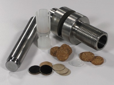
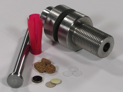
Place an overshot card on top of the shot charge just before crimping to improve overall crimp quality and seal in small shot and/or buffer. Excellent for use with BPI Roll Crimpers.
Our testing lab has proven that poor crimps can alter the performance of an otherwise good load. Overshot cards always produce better, more consistent crimps and this consistency is demonstrated in the standard deviation of loads in our lab. Our ballistic lab recommends overshot cards for better crimps in all loads.
Clear Overshot Disks(either plain or printed with shot size) are also offered for great roll crimping options. See pictures in Additional Images or click on this link.
Shotshell size selection: Use the same size gauge as your hull. Smaller diameter cards also work if your particular size is out of stock. For example, a 20ga overshot card works in a 16-gauge shotshell and so on.

While reloading shot shells and using roll crimps, overshot cards are placed on top of the shot/buffer media to keep everything in the shell. ...Why buy them when you can print them for about 2 cents each?
This is an overshot/wad card cutting die. Insert this die upside down inside your press using a L-N-L bushing adapter. I"ve made provisions for adding a metal washer or other insert to beef up the cutting area. Reem the metal insert to 18.67mm.
This one is an overshot waterwheel, printed as a flat pack then glued together. ...I have included 2 versions of the paddles a single piece on and a 3 piece on that can be printed flat
This one is an overshot waterwheel, printed as a flat pack then glued together. ...I have included 2 versions of the paddles a single piece on and a 3 piece on that can be printed flat
Overshot water wheels In an overshot water wheel the mill race brings the water to the top of the wheel, where it strikes the paddles or buckets and turns the wheel. This is more efficient because as well as the force of the flowing water, the...
12g (12 gauge) Template for cutting out Overshot Cards for Shotgun Rollcrimp Shot Shells If you like my models please consider supporting me on Patreon : https://www.patreon.com/bigmrtong
Friend wanted to know if I could make business cards for him. After some trial and error this what he got. ...Of corse scaled down to .3 so it will be about the size of your palm.
http://www.thingiverse.com/apps/customizer/run?thing_id=66327 Instructions Using the following options: bottom_text_rotation = 0 Move_Image_Left_Right = 30 card_type = 56 top_text_rotation = 0 build_plate_selector = 3 bottom_text_label =...
Sometimes what you do can"t be put on a business card. Maybe you design custom Oilfield Software for fluid management. Maybe you are a photographer or graphic design artist. Perhaps you write code or film porn. Any way it goes a few samples of your...
Wanted a case for business cards. ...Prints quickly on mk MK2s. Fusion 360. I suggest you slightly size the top up a hair so its a snugger fit. 85mmx55mm business card.
http://www.thingiverse.com/apps/customizer/run?thing_id=66327 Instructions Using the following options: Move_Bottom_Text_Up_Down = 43 build_plate_manual_y = 100 build_plate_manual_x = 100 card_type = 71.1 Move_Image_Up_Down = 40 card_count = 40...
Summary Sometimes what you do can"t be put on a business card. Maybe you design custom Oilfield Software for fluid management. Maybe you are a photographer or graphic design artist. Perhaps you write code or film porn. Any way it goes a few samples...
Sometimes what you do can"t be put on a business card. Maybe you design custom Oilfield Software for fluid management. Maybe you are a photographer or graphic design artist. Perhaps you write code or film porn. Any way it goes a few samples of your...
I`m also punching os cards from cereal boxes per your recommendation :thumbsup: I have some 12ga. felt wads that I could punch down to size but I thought the over powder cards we`re of a harder material, like thick cardboard or something along those lines. I also thought the over powder card was a gas seal. I`m thinking with felt being a porous material that moisture would be able to get through. Correct me if i`m wrong here, I may be on the wrong track :idunno:

I use them to cut multiple layers of flannel to make cleaning patches in the diameters I need - they would work for making punches as well. I use a belt sander/disc sander to remove the hardened teeth from the hole saw and then sharpen the hole saw - i.e. bevel the "outside edge" of the bottom which will form a sharp edge and maintain the inside diameter. These mount on an arbor which usually has a center drill bit that is removable - remove the drill bit. Chuck the altered hole saw in your drill press and use a piece of wood on the table - lay your material down and drill through it with the hole saw. The hole saws usually have slots on the side and it makes it easy to stop the drill press, take something like a scratch awl and reach through the slot and push the patches/wad out - then cut another. If you are lucky enough to find a hole saw with the ID that fits you purposes - you could easily stack up three or so layers of thicker cardboard and cut cards or if cutting wads, cut up some 1/2" insulated sheathing or use a celotex type ceiling tile and get a lot of wads. Much easier than hand punching but just be careful to keep material flat on wood on the table so the hole saw has a backer when it breaks through the material you are using. If you leave the teeth on and try it, you"ll end up with ragged edges -- the teeth removed and the edge bevel sharpened on the outside will slice right through.If you know the O.D.of the wad you need for your bore/shell/use - take a set of dial calipers with you when you go looking for the hole saw so you can easily check the I.D. of the hole saw. As an example - remember that a 3/4" holes is designed to cut a hole that is 3/4" hole (.750). The thickness of the side of the material making the hole saw will have to be doubled and subtracted from the O.D. So as an example - a 3/4" hole saw that has sides that are say, 1/8" thick - the two sides would equal 1/4" that would have to be removed from the O.D. of the hole saw to give you the I.D. of the holes - in this example the I.D. would be 3/4" - 1/4" (1/8" of the thickness of the hole saw sides doubled) = and I.D. of 1/2" - which would be the O.D of the wads it would cut. Simplified but you get the idea.

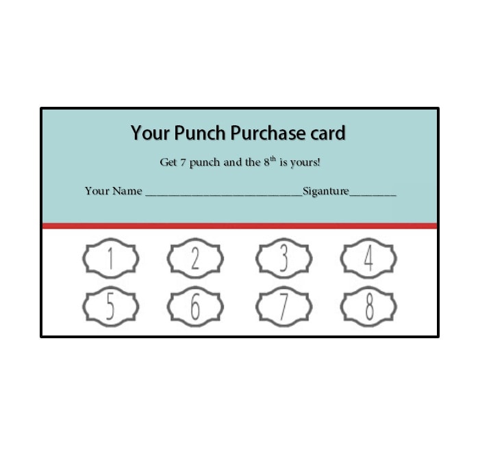
Punch card templates that is suitable for every business and every promotion. Increase your customer loyalty using our stunning punch card templates in word, pdf formats.
The braking system 18 used in the device 10 can be used in other applications and in particular to prevent loss of running tools and other downhole equipment in the event of failure or accidental release from an overshot and/or wireline. In addition, as previously mentioned, the braking system also assists in reducing the speed of a running tool when returning under the action of gravity within drill string or drill pipe in an uphole orientation. Moreover, as depicted in FIGS. 9 and 10, the braking system 18 can be incorporated into a head assembly 200 of any form of running tool or downhole device to hold the tool or device within a drill pipe 202. The head assembly 200 includes a conventional spearpoint 204 which is adapted for coupling to a conventional overshot 206 provided with overshot latch dogs 208. The interaction and operation of the spearpoint 204 and overshot 206 is well known to those skilled in the art and not described in any detail herein.
The braking system 18 also includes an automatically releasable brake lock 242 which acts to ordinarily hold the anchor balls 228 out of contact with the inner surface 240 to allow free running of an associated tool within the drill pipe 202 when attached to a overshot 206, but automatically deploys of the anchor bolts 228 to lock or brake the tool within the drill pipe 202 when the overshot 208 is released from the spearpoint 204.
The automatically releasable brake lock 242 includes an overshot extension sleeve 244, a cap 246, spring 248, locking sleeve 250, balls 252 and floating sleeve 256. The overshot extension sleeve 244 is threadingly coupled at one end to the overshot 206. The cap 246 is threadingly coupled to an opposite end of the extension sleeve 244. The cap 246 further slidably engages the locking sleeve 250, with the spring 248 being disposed about the spearpoint 204 between the end of the extension sleeve 244 coupled to the overshot 206 and the locking sleeve 250. The locking sleeve 250 is dimensioned so that it can extend over the balls 252. The balls 252 are retained about the surface 218 by the floating sleeve 256 which is provided with apertures 258 through which the balls 252 can extend. A further spring 260 is located within the floating sleeve 256 and acts between the spearpoint 204 and the balls 252 urging the balls 252 to roll to an end of the surface 228 with the smallest outer diameter.
When the overshot latch dogs 208 are engaged with the spearpoint 204, the spring 248 urges the locking sleeve 250 over the balls 252 preventing them extending radially outwardly from the apertures 258. In addition, the floating sleeve 256 is forced in a downhole direction bearing against the anchor ball sleeve 224 forcing the anchor balls 228 against the step 214 and thus disposed about a portion of the surface 212 with the smallest outer diameter allowing the balls 228 to be spaced from the surface 240. In this configuration, the tool to which the braking system 18′ is attached is able to run freely in any direction within the drive pipe 202.
However, if the latch dogs 208 become detached from the spearpoint 204 while within the drill pipe 202, the brake lock 242 is automatically released deploying of the anchor balls 228. This arises as follows. With the disengagement of the latch dogs 208, the extension sleeve 244 which is attached to the overshot 206 holds the locking sleeve 250 as the spearpoint 204 and remainder of the assembly 200 starts to fall dragging the locking sleeve 250 with it. Thus in effect the locking sleeve 250 is pulled away from the balls 252. The balls 252 are now free to move radially outwardly as they roll along the surface 218 toward the spearpoint 204 by action of the spring 232. In this regard, the spring 232 urges the anchor ball sleeve 242 and thus the floating sleeve 256 toward the spearpoint 204. With the locking sleeve 250 retracted, the floating sleeve 256 can then roll the balls along the surface 218 against the bias of the spring 260. Simultaneously, the spring 232 urges the anchor balls 228 to roll along the braking surface 212 which, due to its increasing outer diameter results in the balls 228 extending from the holes 226 and into contact with the surface 240.
Assuming for the time being that the drill pipe 202 is disposed in a downhole (as distinct from an uphole) the weight of the tool to which the braking system 18′ is attached together with the action of the spring 232 will effectively wedge the anchor balls 228 between the surfaces 212 and 240 to lock the tool to the drill pipe 202. Now, a fresh overshot 208 can be lowered into the hole to engage the spearpoint 204. As the overshot is now retrieved by a wireline, it pulls the spearpoint 204 and shaft 210 in an uphole direction causing it to slide relative to the anchor ball sleeve 224. As this occurs, the balls 228 are able to roll along the braking surface 212 toward the step 214 thereby releasing the balls 228 from engagement with the surface 240. Simultaneously, the floating sleeve 256 and locking sleeve 250 are caused to slide relative to the shaft 210 back to the configuration depicted in FIG. 7 so that the balls 252 effectively lock the anchor balls 228 from engagement with the surface 250.


 8613371530291