
overshot drilling tool free sample
This invention relates to overshot and safety apparatus for retracting a core barrel inner tube assembly and mechanism to decrease the chances of unintended movement of the inner tube assembly outwardly of the drill string which can result in injury to personnel during up-hole drilling (drilling is at a hole angle that is above the horizontal).
During up-hole drilling with wire line equipment, the inner tube assembly can unexpectly move to and through the outer end of the drill string and injure someone. For example, if the inner tube assembly is not properly maintained, it is possible the inner tube assembly can move to the outer end of the drill string in an uncontrolled manner. To stop such outward movement of an inner tube assembly or the like, it is necessary to consider connecting a device such as a “safety sub” at the outer end portion of the drill sting. A sub is usually a short coupling having male and female thread connections. Such a sub can have a closed end or have a minimum inner diameter portion that is of a small inner diameter than the maximum outer diameter of the outer end portion of the drilling tool that is used in the drill string, for example, a core barrel inner tube assembly or an overshot assembly.
A problem with such a safety sub is that it must be removed from the outer end of a drill string in order to insert a prior art overshot assembly in the drill string preparatory to retrieving a core barrel inner tube assembly when it is filled with core. In removing the sub from the drill string, in order to be able to insert a wire line overshot assembly, the operator is exposed to the open outer end of the drill string through which the drilling tool in the drill string may move outwardly in a dangerous manner whereby the operator is exposed to possible injury when the drilling direction is upwardly. After the overshot assembly is pumped to the inner end of the drill string and then attempting to unlatch (uncouple) the inner tube assembly from its latched condition in the drill string, it is possible to have a mistaken unlatched or a “hung-up” inner tube assembly whereby the overshot assembly is retracted without the inner tube assembly coupled thereto. Again, the operator is exposed to possible injury from the drilling tool if and when it unexpectly moves out of the outer end of the drill string.
In U.S. Pat. No. 3,120,283 to Braun there is disclosed an underground overshot assembly (see FIGS. 10 and 11) that is fluidly propellable to the bit end of the drill string regardless of the drilling direction. The overshot assembly includes a main body pivotally mounting pulling dogs and a valving subassembly that provides an open fluid bypass channel when being retracted though the drill string.
In order to make improvements in overshot and safety apparatus that is particularly usable in up-hole drilling (a drilling direction above the horizontal), this invention has been made.
The overshot assembly includes a main body mounting pulling dogs for movement between an inner tube assembly coupling position and a release position, an annular seal for forming a fluid seal with the interior of a drill string, an elongated overshot tube joined to the main body and valving mechanism resiliently urged to block axial outward flow through the overshot tube. A safety sub is removably mounted to the outer end portion of the drill string while an overshot adaptor is removably mounted to sub to prevent the overshot assembly moving inwardly of the sub and to retain overshot valving mechanism in an open condition. The overshot adaptor includes valving mechanism to permit fluid to be pumped inwardly through the overshot adaptor and the overshot tube and block fluid flow in the opposite direction, the combination of the overshot assembly and overshot adaptor being axially slidably movable a limited amount relative to the sub. When it is desired to retract an inner tube assembly or other drilling tool, the water swivel is removed from the drill string and a disconnect tool is used to pull the overshot adaptor to extend outwardly in the sub. Now the overshot adaptor is unthreaded from the overshot assembly. Then a wire line adaptor is threaded to the overshot tube to close the outer end thereof and a loading chamber is threaded to the sub and fluid under pressure is pumped into the sub for forcing the overshot assembly inwardly.
One of the objects of this invention is to provide new and novel overshot means for use in up-hole drilling apparatus that is usable in combination with a safety sub to minimize danger when a drill tool is in a drill string during up-hole drilling and the outer end of the drill string is opened. Another object of the invention is to provide new and novel overshot and safety apparatus that is retained at the outer end of a drill string while a bore hole is being drilled. In furtherance of the last mentioned object, it is another object of this invention to provide new and novel adaptor means to cooperate with a safety sub and a new and novel up-hole overshot assembly to retain the overshot assembly adjacent to the outer end of a drill string while permitting fluid under pressure being pumped through the overshot assembly when drilling with a core barrel inner tube assembly. An additional object is to provide new and novel overshot means that is fluidly propellable in a drill string in an upward direction when connected to wire line means and block axial outward fluid flow therethrough when disconnected from such wire line means and not mechanically retained in an unblocked fluid flow position.
FIGS. 1A and 1B, when arranged one above the other with their axial center lines aligned and lines A—A and B—B of FIGS. 1A and 1B aligned, other than for a part adjacent to the outer end, form a composite longitudinal section through the drilling apparatus of this invention with the safety sub and overshot adaptor retaining the overshot assembly at the outer end of the drill string and an axial intermediate portion is broken away;
FIG. 4 is an enlarged longitudinal cross sectional view of the outer end portion of the structure of FIG. 1A together with a disconnect tool shown in a position for being rotated and then pulling the combination of an overshot adaptor and an overshot assembly to extend outwardly of the safety sub;
FIG. 5 is a longitudinal cross sectional view showing the wire line adaptor threaded to the overshot assembly tube with the overshot assembly extending within the safety sub;
FIG. 6 is an enlarged longitudinal view of the inner end portion of the overshot assembly with the overshot adaptor removed therefrom and coupled to a wire line core barrel inner tube assembly, an axial intermediate part of the overshot assembly being broken away and only the axial opposite end portions of the core barrel inner tube assembly being shown;
FIG. 7 is a fragmentary transverse cross sectional view of the safety sub, the overshot adaptor and the overshot assembly, said view being generally taken along the line and in the direction of the arrows 7—7 of FIG. 2;
FIG. 8 is in part a fragmentary view of the safety sub and the outer end portion of the overshot assembly and overshot adaptor and in part a somewhat diagrammatic showing of a water swivel and drill rods extending axially outwardly of the safety sub, portions being shown in cross section and axial intermediate portions being broken away;
FIG. 9 is a fragmentary view generally taken along the line and in the direction of the arrows 9—9 of FIG. 4 other than the tool has been rotated 90 degrees; and
Referring now in particular to FIGS. 1A, 1B and 6, there is illustrated an overshot assembly, generally designated 10, in a hollow drill string 13 which is made up of a series of interconnected hollow drill rods (tubes). Even though the drilling direction is not shown as being upwardly, the drill string 13 is in an upwardly extending bore hole 12 drilled in rock or other types of earth formations by means of an annular core bit 11 which is at a higher elevation than the axial outer end of the drill string. The pump apparatus located at the drilling surface and indicated by block 85 pumps fluid under pressure through a conventional water swivel 88 and into a safety sub, generally designated 20, which is removably mounted to the outer end of the drill string 13. The bit in the bore hole 12 may be at a considerable elevation above the drilling surface but at a considerable depth below the earth surface.
The overshot assembly includes a pair of axially elongated pulling dogs 14 having their intermediate portions pivotally mounted in a slot in the overshot main body 16 by a pivot pin 15. The outer end portions 14B of the dogs are resiliently urged transversely away from one another by a spring 18 mounted on studs 17 that are joined to the dogs (see FIG. 6). The movement of the dog jaws 14A at the inner end portions of the dogs toward one another is limited by a pin 19 mounted to the main body and extending between the dogs inwardly of the pivot pin 15.
Referring in particular to FIG. 3, the enlarged inner and outer diameter inner end portion 23A of the axially elongated overshot tube 23 is extended into the tubular outer end portion 16B of the main body and secured thereto by a pin 24. The outer end portion 23B of the overshot tube is internally threaded at 23C to have the outer end portion of the reduced diameter tubular portion 27A of adaptor tube 27 of the overshot adaptor, generally designated 25, threaded thereto (see FIG. 2).
The adaptor tubular portion 27A has a plurality of ports 28 closely adjacent to its inner annular edge 27B which opens to the annular clearance space radially between the outer peripheral wall of the adaptor tubular portion 27A and the peripheral wall of the overshot tubular portion 23A. The overshot tubular portion 23 has ports 29 that open to the above mentioned clearance space axially outwardly of the main portion 23A. There is a valve member 30 having a head portion 30A that is resiliently urged by a spring 31 to a closed position to abut against the inner annular edge portion 27B of the adaptor tube 27 when threaded to the overshot tube, the spring acting between the head portion and the pin 24. Further, when the adaptor tube is not threaded to the overshot tube, spring 31 resiliently urges the valve member to a closed position abutting against valve seat 32 and permits the valve member being moved to an open position by fluid under pressure being exerted on the valve member in an inward direction.
The valve member has a valve stem 30B with an elongated slot 37 through which pin 24 extends to mount the valve member to the main body for limited relative axial movement. When the adaptor tube 27 is moved outwardly relative to the main body 16, the valve member is resiliently moved to have the head portion 30A abut against the valve seat 32 formed at the juncture of the bore portions of the enlarged diameter portion 23A and the reduced diameter portion 23B to block fluid flow between ports 29 and the adjacent part of reduced diameter tubular portion 23B and axially outwardly (see FIG. 6). A dog retainer 33 is mounted to the inner end portion of the valve stem to move therewith in the main body tubular portion 16B between a position extending between the outer ends of dogs to block the pulling dogs jaws spreading apart to a release position to allow the spear point 35A of an overshot coupling member 35 of a drilling tool, generally designated 40, move sufficiently axially inwardly between the jaws for being coupled to the overshot coupling member when the valve head abuts against the adaptor tube 27 and a position allowing the jaws spreading to allow the overshot assembly be coupled to the overshot coupling member when the valve member abuts against the valve seat 32 such as shown in FIG. 6. The tool may be any one of, for example, a core barrel inner tube, one having a plug bit, an earth sampling tube etc. The tool may be of a type fluidly propellable to the bit end of the drill string, for example the core barrel inner tube assembly of FIGS. 3A, 3B, 4A, 4B of U.S. Pat. No. 5,934,393 and FIG. 13 of U.S. Pat. No. 5,257,620.
The overshot assembly also includes an annular retainer 41 with the reduced diameter tubular portion 23B extended therethrough and abutting against the outwardly facing shoulder formed at the juncture of tubular portion 23B with enlarged diametric portion 23A of the overshot tube. The tubular portion 23B also extends through the annular, resilient fluid seal members 42. Each seal member has an outer peripheral cylindrical surface portion to at least substantially form a fluid sealing fit with the inner peripheral wall of the drill string as the overshot assembly moves axially inwardly in the drill string. Advantageously, each of the fluid seals 42 are of a construction the same as or similar to the seal member E of the inner tube assembly of U.S. Pat. No. 5,934,393 that forms a fluid seal with the drill string and thus will not be further described. The fluid seal members 42 block fluid flow bypassing the overshot assembly through the clearance space between the overshot tube 23 and the inner peripheral wall of the drill string. The seal members are retained between the annular member 41 and a seal nut 43 that is threaded on the tubular portion 23B while a retainer nut 44 is also threaded on the tubular portion 23A to abut against the annular member 41. The overshot tube 23 has an axial intermediate portion extended through a coil spring 45, the inner end of the spring 45 being mounted to the retainer nut to extend outwardly thereof.
Referring to FIG. 2, the safety sub 20 is tubular and has an axial intermediate, minimum diameter bore portion 47 of a diameter to have the reduced diameter overshot tube portion 23B slidably extended therethrough. The sub includes an axial inner male pin 48 for being threaded to the outer end of the drill string 13 and has an axial bore portion 49 that at its minimum diameter part is of a larger diameter than that of bore portion 47 and opens to bore portion 47 to provide an axial inner facing shoulder 50. The outer end of bore portion 47 opens to a larger diameter bore portion (valve chamber) 51 to provide an outwardly facing shoulder 52 while the opposite end of the bore portion 51 opens to a larger diameter box portion 54 to provide an outwardly facing shoulder. The male pin portion 55 of either a conventional water swivel 88 or the male pin portion 58 of a loading chamber 57 are threadedly connectable to the box portion 54.
The adaptor tube 27 includes an axial outer, annular head portion 27D having a bore 74 of a larger inner diameter than the inner diameter of the bore of tubular portion 27A of adaptor tube 27 and opens thereto to provide an outwardly facing shoulder 71 with a plurality of holes 72 opening to the shoulder and the bore portion of tubular portion 27A. The head portion has external threads for being threaded to the internally threaded inner end portion of the valve body 73, the outer diameter of each of the head portion and the valve body being greater than the diameter of sub bore portion 47 whereby the head portion and valve body are abuttable against shoulder 52 to limit the axial inward movement of the overshot adaptor relative to the sub. Further, the valve body is of a lesser axial length than the length of the chamber 51. Thus, when the valve body is abutting against shoulder 52, the outer transverse surface 73A of the valve body is a significant distance inwardly of the shoulder 58. Intermediate the valve seat 75 and surface 73A, a pin 84 is mounted to the valve body to extend diametrically across bore portion 78.
In order to facilitate moving the overshot adaptor outwardly of the box portion 54 sufficiently to provide easy access for separating the overshot adaptor from the overshot assembly, there is provided a disconnect tool T that has an axial outer handle portion 82 and a reduced diameter, axial inner rod portion 79 of a diameter to be extendable into the valve body bore portion 78. The axial inner part of the rod portion has a slot 81 that extends diametrically thereacross and opens through its inner transverse surface 79A. Further, the rod portion has diametrically opposite cutouts 92, 93 axially outward of the transverse surface and open to the rod peripheal surface and to the outer end of the slot 81 in the same angular direction whereby when the rod portion is moved axially inwardly to have the pin 84 abut against the outer end of the slot 81 the rod can be rotated about 90 degrees to have the axial inner transverse surfaces 92A, 93A of the cutouts abuttable against the pin 84. As a result, with the water swivel 85 or other structure extending outwardly of the box portion 55 separated from the safety sub, the tool rod portion 79 can be moved into bore portion 78 to have the pin 84 extend into the outer end of slot 81 (see FIG. 4) and then the tool rotated to have the pin located in the closed end portions of the cutouts 92, 93 that extend about 90 degrees relative to slot 81 (see FIG. 9). Now, upon moving the tool axially outwardly, the overshot adaptor, together with the overshot assembly, is moved sufficiently axially outwardly relative to the safety sub whereby the overshot adaptor can be separated from the overshot assembly.
In use, with the overshot adaptor separated from the overshot assembly and the safety sub, the outer end portion of the overshot tube 23 is extended through the sub bore portion 49 and into bore portion 47 to extend axially outwardly of the sub. The axial inner end of the adaptor tube is extended into the outer end portion of the overshot tube 23 and threaded to form a threaded connection at 23C. As the overshot adaptor is extended into and threadedly connected to the overshot assembly, the adaptor tube 27 forces the valve member 30 inwardly against the action of spring 31 whereby the dog retainer 33 is moved between the outer ends of the pulling dogs to prevent the jaws 14A spreading apart sufficiently to slip over the spear point 35A and couple to the overshot coupling member 35. Now, the axial inward movement of the threaded combination of the overshot adaptor and the overshot assembly relative to the safety sub is limited by the valve body abutting against the shoulder 52 while the axial outward movement is limited by spring 45 abutting against shoulder 50.
After the core barrel inner tube assembly 40 or similar drilling tool is inserted into the outer end of the drill string 13, the inner end portion of the combination of the overshot assembly and overshot adaptor is inserted into the drill string, pushing the drilling tool 40 inwardly and then the safety sub is threaded to the outer end of the drill string. Thence, the water swivel 88 is threaded to the safety sub to which a supply of fluid under pressure 85 is attached. In the event the drilling direction is upwardly, the drilling tool is of a conventional type that can be fluidly propelled in the drill string adjacent to the bit end 11. If the drilling tool is an underground wire line core barrel inner tube assembly, one example being that of FIGS. 3A and 3B U.S. Pat. No. 5,934,393, fluid under pressure forces the valve ball 80 off the valve seat to allow fluid to flow through a bypass channel, i.e. through tube 27 and through ports 28, 29 to the annular clearance space between the overshot main body and the drill string to bypass fluid seals 42 and force the inner tube assembly inward until its core lifter 34 is located adjacent to the bit opening through which the core being drilled extends.
After the inner tube assembly is at the bit end of the drill string, drill fluid is pumped into the drill string and the drill string rotated to drill a core. In the event the core barrel (not shown) of the inner tube assembly is of an extended type or the core barrel is longer than the drill rods being used, during the drilling operation, pumping of fluid under pressure is discontinued whereby the valve ball 80 is resiliently moved to prevent axial outward flow in the drill string, rotation of the drill string stopped, and then the water swivel removed. Now an additional drill rod(s) 89 may be threadedly connected to the box portion of the sub and thence the water swivel 88 threaded to the outer end of said additional drill rod(s). Thereafter, fluid under pressure is pumped into said additional drill rod which forces the valve ball 80 to move inwardly and the drill string rotated to continue the core taking operation.
When the core receiving tube (not shown) is filled, rotation of the drill string is stopped and the pumping in of fluid is discontinued together with removing the water swivel and removing drill rods, if any, extending outwardly of the safety sub. Since the valve ball 80 seats on the valve seat, fluid flow axially outwardly through the overshot adaptor overshot assembly is blocked. Using the disconnect tool T, the overshot adaptor overshot assembly combination is pulled outwardly in a manner previously indicated to have the outer end portion thereof extend outwardly of the sub box portion. Thence the overshot adaptor is unthreaded from the overshot assembly and withdrawn therefrom. As the overshot adaptor is unthreaded from the overshot assembly and moves axially outwardly relative thereto, the valve member 30 is resiliently moved outwardly to abut against the valve seat 32 to block fluid flow from inwardly of the seals 42 and then through the ports 29 and into tubular portion 23B, the valve member blocking axial outward flow through the bypass channel provided by the overshot tube and ports 29. Desirably, the axial length of the threaded connection 23C is sufficiently great that prior to the overshot adaptor being completely unthreaded from the overshot assembly, the valve member 30 seats against the valve seat 32. During the separation of the overshot adaptor from the overshot assembly, the axial outward movement of the overshot assembly relative to the sub is limited by the spring 45 abutting against shoulder 50. Accordingly, time is not lost in having to drain the drill string and insert an overshot assembly into the drill string since the overshot assembly is already extending within the drill string and water or other drilling fluid in the drill string is not drained from the drill string.
After the overshot adaptor is removed and while the overshot tube portion is extending outwardly of the sub box portion, the wire line swivel (wire line adaptor) 90 with a wire line 91 connected thereto is threadedly connected to the overshot tube threaded portion 23C. The male pin 58 of the loading chamber or stuffing box 57 is threadedly connected to the sub box portion 54 and fluid under pressure is connected to the loading chamber and pumped into the drill string to fluidly propel the overshot assembly to the drilling tool 40 and upon the pulling jaws encountering the spear point 35A, the jaws are pivoted to their release position to allow the spear point pass therebetween and then the pulling dogs are resiliently urged to their coupling position to couple to the overshot coupling member 35. It is noted that during the unthreading of the overshot adaptor from the overshot assembly, the dog retainer 33 moves axially outwardly of the pulling dogs and as a result the dogs may pivot to move axially inwardly of the spear point 35A to couple thereto.
After the overshot assembly has coupled to the drilling tool 40 and the discontinuance of the application of fluid under pressure to the drill string, the wire line is retracted whereby the drilling tool 40 is unlatched from the drill string, if latched thereto, and the drilling tool and overshot assembly are moved to have the coil spring abut against the shoulder 50. If the drilling tool is retracted with the overshot assembly, the spring 45 is further compressed and the overshot assembly extends further outwardly of the sub than the extent of protrusion after the overshot adaptor had been disconnected from the overshot assembly and no external force was applied to the overshot assembly. This can be seen upon removing the loading chamber from the sub. Only after the operator is certain that the drilling tool 40 has been retracted with the overshot assembly, the loading chamber 57 and then the safety sub can be safely removed from the drill string and thereafter the overshot assembly and the drilling tool removed from the drill string. In the event it does not appear that the overshot assembly has retracted the drilling tool and more than one attempt is made by pumping the overshot assembly inwardly in an attempt to retract the drilling tool, greater precautions have to be taken in removing the sub. The above assumes the drilling direction is upwardly.

Drilling tool fishing is probably every driller’s least favorite activity. But it happens. There are a huge number of tools available to fish almost anything out of the hole. For drill pipe and collars, there are overshots and spears — in many sizes for almost any job. But, when it comes to loose junk on the bottom of the hole, things get a little more interesting. It might be a loose bit, a wrench, a sledge hammer or tong dies. Anything that can fit in the hole will sooner or later end up on the bottom. I reckon it’s human nature, or Murphy’s law, but it happens.
Most commercial fishing tool companies have pretty sophisticated tools, such as reverse circulation junk baskets, and all kinds of well-engineered tools to do the job. But, sometimes, they are not quite what a customer needs. If the fish is large in relation to the hole size, such as a bit, a reverse basket will not pick it up because of the wall thickness. Something else is needed. Or, if the hole is just not worth the expense of using a commercial fishing company, a driller may opt to build his own fishing tool for the job.
This brings me to a tool that is often overlooked, but has been around forever and recovered a lot of junk in the hole: the poor-boy basket. Most fishing companies don’t push them because they are not fancy high-dollar tools that make great testimonials, but they work and can be built by the driller on location.
The layout and design of the fingers is very important to the operation of the tool and successful recovery of the fish. I have built these for years and pretty well have it down, so I thought I’d share with you how to lay out the leaves on a poor-boy basket for your best chance of recovery.
Once you’ve built your basket, here is the running procedure:Go in the hole at moderate speed, watching for ledges or doglegs. The basket is a delicate tool, and you need it intact when you get to the bottom.

The present disclosure is directed to a fluid operated fishing tool and more particularly to one which has a soft contact or a soft set tool. It is especially adapted for use in grasping and holding a fish (an item to be retrieved) which does not necessarily have an easily gripped upper end such as a drilling motor stem. It will be discussed in the context of retrieving a typical elongate cylindrical device that may have a smooth upper end, and particularly one which does not have a spear head, or indeed, a fish of any shape.
The fishing tool of the present disclosure is a type of retrieval tool or overshot which reaches around and grasps the fish. It is constructed with a soft set or soft touch mechanism. The soft set mechanism is especially desirable in light of the varied size and shape of the upper end of the fish. The shape of the fish may be known, but in some instances, it is completely unknown. Likely, it will be an elongate device having no particular anticipated shape. Whatever the case, the present device is constructed to reach over the fish and surround the upper end of the fish. The fish can be shredded, twisted, bent, or otherwise parted. It can just as easily be an elongate cylindrical member which simply has no shoulders, no threads, no undercut shoulder, no serrations or knurled surface, etc. It can be smooth metal or rough with no limit. This soft set structure reaches over the fish and conforms to the fish regardless of its shape. The fish is gripped by a surrounding resilient sleeve which is on the interior of the present overshot device. This sleeve fits around the fish with some clearance. The sleeve is on the interior of a cylindrical housing. By the proper actuation of the present device, fluid pressure is applied behind the sleeve so that the sleeve expands radially. It expands inwardly to grasp the fish which is enclosed within the sleeve. The upper end of the sleeve is free floating on a sealed surface of a stem which construction allows the sleeve to contract. The sleeve floats to enable it to conform to the fish. By having the top free floating, the sleeve material is in compressed when a pull is exerted. This allows for more strength in the tool. Also, the weight of the fish tends to help set the sleeve when coming out of the hole. While the present apparatus is able to transfer a tremendous amount of pulling force to the fish, there is the possibility that the fish will not break free. In that instance, it is then desirable that the fish be released. The present apparatus includes a mechanism by which release is accomplished. The soft set tool is set by pumping incompressible fluid behind the sleeve. That space is later evacuated of high pressure fluid and the pressure is released by dropping a ball to seat on a pinned sleeve. A predetermined pressure will shear the pins and move the sleeve downward to open access ports to the pressure chamber. The same movement opens ports to the annular area to eliminate the problems of pulling a wet string. This enables release of the fish and permits relaxation of the sleeve. In that instance, the sleeve will relax and expand radially outwardly for restoration to its original shape, and thereby release the fish. This makes retrieval of the fishing tool something easily done when the fish cannot be readily moved.
In very general terms, the tool of the present disclosure threads to a tubing string which enables the tool to be lowered in a well where a fishing job is to be conducted, and extend over the fish. The tool incorporates an elongate cylindrical upper end which has two internal sleeves which are selectively plugged by dropping a specifically sized ball in the tubing string. Dropping the smaller ball initiates seating on the lower sleeve, shutting off circulation thru the tool and allowing a predetermined pressure to be applied in the pressure chamber to set the soft set grapple. The same pressure will shear the sleeve pins. This allows the sleeve to move downwardly to open ports to the annular area, thereby establishing circulation. The setting pressure is retained in the setting chamber by back pressure valves. This ball stops flow axially of the tool and diverts the flow into a passage in the sidewall. This passage is ordinarily closed when flow is axially through the tool, closure being accomplished by a spring actuated check valve. When the check valve is overpowered, it delivers fluid under pressure controlled at the wellhead so that pressure build-up occurs in a chamber within the tool. The chamber is concentric around and coextensive along a resilient sleeve which is forced to shrink radially inwardly by the surrounding fluid pressure. This pressure causes the resilient material of the sleeve to conform against the surface of the fish and to grasp the fish so that it is held. As will be detailed substantially with the development of the present disclosure, the fish is held so that axial pulling can occur, hopefully retrieving the fish in the fashion of an overshot retrieval too. In the event that the procedure requires later release of the fish, a larger ball is dropped in the tubing string and lands on a larger bore seat at the upper end of the tool. By increasing pump pressure at the wellhead, this sphere in conjunction with a moveable sleeve is moved downwardly, breaking a set of shear pins. When it moves, the sleeve closes off or blocks the lateral passage by which fluid is introduced around the sleeve. Moreover, this enables a passage to be actuated which voids the chamber around the sleeve so that any build-up of pressure in that area is relieved. This permits the sleeve then to relax. Moreover, the downward movement opens a passage above the ball seat to establish circulation. This eliminates the necessity of pulling a wet string, reducing mud spillage. In this type of operation, the tool also has fill-up valves at the bottom of the tool and air release valves at the top. Both of these valves close when adequate pressure is achieved in the setting chamber.
FIG. 1 is an elongate sectional view of the elongate tool in three portions identified as FIGS. 1A, 1B, and 1C which collectively show a sectional view through the length of the tool from the top to the lower end with the tool in the relaxed state so that a fish shown in dotted line can be positioned within the resilient sleeve for grasping and subsequent retrieval;
FIG. 6 is a view of the tool similar to FIG. 5 but showing the sleeve forced downwardly by pressure fluid from the wellhead sufficiently to break a set of shear pins for moving the sleeve so that no fluid is behind the resilient sleeve and the annular ports are open.
Attention is directed to FIG. 1 of the drawings which will be described in detail proceeding from the top to the bottom. This description sets out particulars of the construction and operation of the embodiment 10 which is shown in three segmented views which are longitudinal sectional views of the elongate cylindrical device. The tool 10 is connected to a tubing string, and the top joint of the tubing string 11 is shown. A sub 12 is provided with conventional threads to locate a box end at the upper end of the tool 10. The sub threads to an elongate thick wall housing 13 by means of a threaded connection 14. An internal sleeve 15 is included at an internal shoulder within the housing 13, and one or more appropriate shear pins 16 are included. An externally connected passage 9 opens through the wall of the housing 13 and the short sleeve 15; the inner sleeve 18 closes the passage 9 which is controllably opened in FIG. 6. The shear pin 16 extends radially inwardly to fasten in an upward location a larger sleeve 18. The number of pins, diameter and hardness of metal determines the force required to shear the pins. The force is changed by modification of these variables. The sleeve 18 has an upper end shoulder 17 which is included to catch an support a large sphere as will be described with respect to FIGS. 5 and 6 jointly. The sleeve 18 is constructed with a radially directed passage 19 which connects to an external groove around the sleeve 18 which aligns with a high pressure passage 20. The passage 20, there being several such passages in the housing 13, extends downwardly to a pressure operated check valve 21. Flow upwardly is forbidden by the check valve cooperative with the valve seat. Flow downwardly does not occur until the force of its bias spring is overcome. Flow downwardly through the passage 20 is delivered into an annular chamber 22. The chamber 22 has two or three such check valves delivering flow into it, and it also communicates with bleed valves 23, two or three in number, preferably opening to the exterior by means of an air bleed passage 24 which vents to the exterior. One or several passages are used in the system. The passages 24 do not permit flow if the check valve 23 is raised by the flow and contacts against the seat above the check valve element. The check valve, however, is able to move downwardly. It moves downwardly where it rests on a crenalated support sleeve, this sleeve providing support so that air can flow past the check valve without raising it. When drilling mud is introduced into this annular chamber, the increase in fluid density of the mud raises the check valve element 23 and causes it to close. This drains the annular chamber 22 of air but limits the escape of drilling fluid.
The tool 10 has an axial central passage which is open to fluid flow. Fluid flow proceeds directly downwardly through the tubing string 11 and through the sleeve 18 in ordinary circumstances. However, fluid flow is also permitted to be diverted through the lateral passage 19 so that it enters the passage 20 and proceed downwardly in the housing as described. There is another lateral passage through the sleeve 18 at 25, but this passage does not align for lateral flow as shown in FIG. 1A. Later, it will move down to align with the annular chamber 22. That assures that the chamber 22 can drain into the sleeve 18 to reduce pressure in the chamber 22.
The sleeve 18 is pinned in the up position in FIG. 1A. There is a range of travel permitted for it so that it can move downwardly until it abuts against the shoulder 26. The shoulder 26 limits downward travel. Below the shoulder 26, there is a more narrowly defined passage in the movable sleeve 27. This particular sleeve again is pinned in location by one or more shear pins. Its passage is more narrow, and it therefore will not permit passage of a sphere 29 which is dropped in the tubing string for the purpose of starting operation. The ball or sphere lands on the sleeve 27 to plug that sleeve. On the increase of pressure applied to the tool string, the sleeve then is able to move. The sleeve 27 covers over a bleed passage 28 to the exterior of the tool 10 so that any standing well fluid captured above the ball 29 and sleeve 27 is permitted to bleed to the outside. This decreases the amount of spillage when the tool 10 is pulled from the well. The sleeve 27 is pinned to a surrounding cage 30 which incorporates a set of slots 31 at the lower end which extend along the cage 30. The shearing force required to move the sleeve 27 is correlated with the setting pressure necessary to set the soft grasp element so that when the selected pressure is reached, the sleeve 27 moves down. The pressure below the packoff sleeve 27 is relieved thru the pressure opened valve in the passage 32. This is necessary because the pressure fluid below will be contained or trapped between the sleeve 27 and the soft set grasping element to be described. The slots have a surrounding external groove registered with a lateral passage to the exterior of the tool, the passage 32 being incorporated to direct fluid flow from the axial passage to the tool exterior to assure that there is no relative pressure differential between the inside of the tool and the exterior. The axial passage through the sleeve 27 extends farther into the next set of structural components as will be described.
The housing is formed of multiple components. A threaded connection at 33 is located where disassembly can easily occur to construct and install the check valves illustrated in FIG. 1A; this threaded connection enables the housing 13 to be extended therebelow by the incorporation of the next housing section 34, and that extends downwardly to the next threaded connection at 35. This enables the next housing section to be attached which, at this juncture, has the form of internal and external concentric spaced apart structural elements which define an annular flow space. There is therefore an inner mandrel 36 with the threads 37 on the lower end of the housing piece 34. There is also an outer component 38 which is concentric thereabout and which makes the threaded connection 35. These two mandrels 36 and 38 define a gap 40 therebetween in FIG. 1B. This annular chamber 40 will be discussed in some detail hereinafter, it being noted that the chamber 40 is provided with fluid flow passages 39 at multiple locations in the housing section 34 thereabove. Moreover, these two concentric pieces which define the chamber 40 also continue to define the central flow passage 41 downwardly through the tool so that it extends as shown in FIG. 1B. The inner mandrel 36 is constructed with a shoulder 42 which supports a resilient sleeve alignment ring 43. The ring 43 is able to telescope on the mandrel 36. The mandrel 36 is provided with the downwardly facing shoulder 42 as mentioned and is able to guide and limit movement of the ring 43. The chamber 40 is on the exterior of the mandrel 36. The mandrel 36 terminates below the shoulder 42, and at the region, it incorporates a surface which permits sliding movement of the ring 43. The ring 43 provides stiffness and alignment for axial sliding movement of an expandable resilient sleeve 48. The sleeve 48 is stiffened by the ring 43 at the upper end, the ring joined by means of an anchor ring 44 recessed internally and bonded to the resilient material forming the sleeve. The ring 43 the sleeve 48 retain fluid pressure where they contact the mandrel 42. The sleeve 48 is preferably formed of resilient material having physical characteristics of rubber. The precise material can be varied depending on the degrees of flexibility required, the temperatures of the well during tool use, and other details relating to its operation.
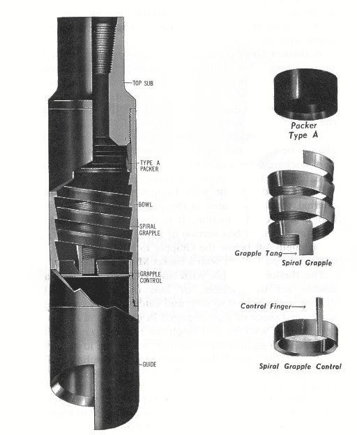
A fish is indicated in dotted line by the numeral 50. This is typical of the type of device retrieved through the use of the present invention. Moreover, it is illustrated with no underside shoulder which enables a grappling tool or overshot having a bowl wedging inwardly a set of collet fingers with serrations to grasp the fish. Also, the fish may or may not have a conventional cylindrical shape, and the fish may or may not be smooth. Here, it will simply be assumed that the fish is difficult to grasp because it is an elongate member such as a pipe without a cylindrical shape. The resilient sleeve 48 is positioned about the fish by stabbing the fish into the soft set overshot 10 of this disclosure. At the juncture, no particular grip has been accomplished. The stabbing action can occur while drilling fluid is circulated downwardly through the passage 41 shown in FIG. 1B and flows over the fish to assure easy nesting of the fish in the sleeve 48. As shown now in FIG. 1C, the sleeve 48 is the primary component which surrounds and grasps the fish. To be sure, the outer body 38 extends around and below the fish, but it does not engage the fish in the sense of grasping it. The outer body or mandrel 38 threads to a bowl 51 which has an inner tapered face or surface 52. This connects with an enlarged skirt 53 which enables the device to surround part or most of the fish. The fish is aligned in the bowl 51 and is forced upwardly so that it registers in the resilient sleeve 48. The fish is permitted to stab as deeply as possible into the soft set overshot until it shoulders against the downwardly facing shoulder 54, better shown in FIG. 1B as part of the inner mandrel 36.
The bowl 51 threads to the outer body 38 at a set of threads 55, and the bowl at its upper shoulder supports a ring 56. The ring 56 is drilled with a radial passage 57 which opens into a fill up valves assembly at 58. When drilling fluid is encountered in the bore while running the tool into the hole, the chamber 40 starts to fill from the bottom thru the fill up valve 58 in FIG. 1C. Air escapes through the bleed valves 23. Pressure is induced through the check valves 21. Fluid rises in the chamber until the chamber fills through the valves 58 and air release valves 21 are enclosed. This enables the chamber 40 to fill from the bottom, and forces evacuation of any air bubbles that might be in the chamber 40. The bubbles float upwardly and are evacuated as previously mentioned. The air bubbles are evacuated so that only incompressible fluid is then captured in the chamber 40. The incompressible fluid fills the chamber. It then is able to provide pressure against the sleeve 48 to force it radially inwardly. This chamber 40 is isolated at the lower end of the sleeve 48 by virtue of an anchor ring 60 integrally constructed with the ring 56. This assures that the sleeve does not leak at the lower end.
Attention is now directed to Fig. 2 of the drawings which shows a portion of the tool with a modified sleeve construction. This will be identified as the embodiment 70. It is similar in the upper portions. To this end, it also incorporates the inner mandrel 36 concentric within the same outer body 38 as previously mentioned. The annular flow space 40 again is incorporated but it is plugged as shown in FIG. 2 by means of a ring shaped plug 71. The plug is sealed on the interior and exterior cylindrical surfaces so that the plug does not permit fluid to flow therebelow. The cylindrical plug functions as a movable piston. Moreover, the plug connects with a modified form of resilient sleeve 72. The sleeve 72 has a greater wall thickness so that it expands radially inwardly when axially compressed by movement of the metal piston 71. The lower end of the plug is anchored in the same fashion as shown in FIG. 1C and hence that part of the structure differs only in the increased thickness of the sleeve 72. The lower end of the structure thus follows the same description applied to FIG. 1C with regard to that portion of the apparatus. The sleeve 72, when subjected to axial loading, expands radially outwardly and inwardly, but outward expansion is fairly well constrained by the close spacing of the resilient sleeve 72 within outer body 38. Because of this lack of space on the exterior, any expansion is directed inwardly to engage by gripping a fish which is caught within this particular embodiment 70. Operation of the structure 70 illustrated in FIG. 2 will be detailed with regard to FIG. 4 of the drawings.
Assume that a fish has been registered within the soft set overshot 10. Assume that fluid has been pumped through the tubing string from the surface and that the operator is then ready to retrieve the fish. The ball or sphere 29 is dropped in the mud flow and is delivered through the tubing string and ultimately lands as illustrated in FIG. 1A. Prior to that, fluid flow was down through the tool 10 so that the interior and exterior of the tool were at a common pressure. At that juncture, the tool is not set. When the sphere 29 lands at the illustrated location shown in FIG. 1A, continual pumping through the tubing string results in an increase in flow into the passage 20 shown in FIG. 1A, flowing downwardly past the check valve 21 and filling the annular chamber 22. It flows downwardly through the passages 39 to fill the annular chamber 40 shown in FIG. 1B. Any air that might have been captured in that area bubbles to the top and escapes through the bleed valve 23 provided for that purpose. When drilling fluid starts flowing in that area, the bleed valve element 23 closes, thereby capturing incompressible fluid in that chamber so that squeezing can occur. As the pressure at the wellhead is then increased, the increase in pressure is observed in the annular chamber 40 on the exterior of the resilient sleeve 48. Contrasting that sleeve in the relaxed state in FIG. 1B, it will be observed in FIG. 3 to expand, but the expansion forces the resilient material radially inwardly in response to pressure so that it grasps the fish and engages the fish 50 by taking on the shape of the fish. The setting pressure is sufficient to develop the force necessary to shear the pins and allow the sleeve 27 to move downward. The downward motion will expose the drain holes 28 to dump the fluid in the string so that the fish may be retrieved without pulling a wet string. Since the resilient sleeve will set around the fish, and the ball is in place atop the sleeve, the valve controlled passage 32 relieves the trapped pressure fluid caused by the downward travel of the sleeve 27. The fish is gripped around a very large portion of its area, and in particular that portion in registry with the sleeve so that the fish is firmly and tightly held. Moreover, the resilient sleeve, now in this gripping shape, is able to impart a lifting force to the fish. A pull is taken on the tubing string and the soft set overshot 10 is then raised, and this of course raises the fish 50 if it will break free. In the ordinary circumstance, it will break free and is retrieved, held snugly and firmly in the resilient sleeve as shown in FIG.3 of the drawings. Assuming this is successfully done, the tubing string is retrieved to the surface along with the soft set overshot 10 and the fish 50. The grip of the sleeve on the fish is enhanced by reaction of the resilient material holding tighter as it is pulled. The results from the tendency of the resilient sleeve to tighten around the fish when the tool 10 is pulled.
At this juncture, pressure differential across the resilient sleeve 48 is released and it is free to expand, restoring its original shape. This enables the fish 50 to be released by pulling on the tool. Also, when the sleeve 18 is moved downward, it opens ports 9 to the annular area to eliminate having to pull a wet string.
The present invention relates to an overshot tool having means for engaging and disengaging a latch in a core barrel head assembly used in core drilling operations and in particular although not exclusively to an overshot tool having an automated latching control mechanism to allow automated coupling and retrieval of the head assembly from within a bore hole. BACKGROUND ART
Diamond core drilling utilises an annular drill bit connected to a core barrel assembly. The core barrel is attached to the end of a number of tubular drill rods connected to form a drill string. The drilling progressively removes cylindrical cores of rock or material through which the drill and drill tube advance using a sequence of runs. This type of drilling utilises an inner tube assembly which has an inner tube connected to a head assembly to receive the core sample. The head assembly comprises a latch body connected to a valve housing which in turn is connected to a bearing housing which in turn is connected to an inner tube connector. The inner tube assembly connects to the inner tube connector and may comprise an inner tube, core lifter and core lift case. The inner tube assembly locates within a core barrel which comprises a combination of drill bit, reamer, outer tube, landing ring and locking coupling. The inner tube assembly can be retrieved from the surface when the inner tube is full. Empty inner tube assemblies can be delivered from the surface to the bottom of the drill string in order to recommence drilling.
The drill bit is advanced by rotating the drill string while applying downward pressure. In addition, drilling fluid such as water or drilling muds are pumped through the centre of the drill string, past the inner tube assembly and through the end of the drill bit in order to carry cuttings and other drilling debris to the surface via the annulus between the wall of the hole and the external surface of the drill string.
The hole being drilled may range from vertical, angled downwardly, horizontal, inclined upwardly or directly upwardly. The holes being drilled may be either normal or dry. In dry holes, the drilling fluid drains away or partially drains away naturally through crevasses or other openings in the rock strata through which the drill passes. In normal holes, the drilling fluid does not drain away.
Of course, in the case of horizontal or near horizontal holes, it is likely that drilling fluid would naturally drain away particularly when the inner tube assembly is being retrieved or after the inner tube assembly is pumped back into the end of the drill string.
With either locating an inner tube assembly within a drill string or retrieving an inner tube assembly, when the inner tube is full, it is most often the case that an overshot tool is used to either lower the inner tube assembly into place, be used to pump the inner tube assembly into place or be lowered by itself to retrieve the inner tube assembly. In the case of a dry hole, the overshot tool will hold the inner tube assembly and their combined weight will allow the inner tube assembly to be lowered into position. In the case of a wet hole, or where the hole is partially wet or where the hole is horizontal, inclined upwardly or upwardly vertical, then the overshot tool has a sealing section which is fluid tight and enables fluid pressure to push the overshot tool and the attached inner tube assembly along the drill tubing.
The overshot tool, when used to retrieve an inner tube assembly when the inner tube assembly is full, can either fall under gravity to latch with the core barrel assembly or again be pumped into place to latch with the core barrel assembly.
The overshot tool needs to cooperate with this latch so that the inner tube assembly can be held with respect to the overshot tool when it is being placed into position within the drill string and core barrel or alternatively must cooperate with the latch when the overshot tool is being used to retrieve the inner tube assembly.
In the case of retrieval, the overshot tool needs to engage the latch so that it releases the inner core assembly from the core barrel while at the same time the latch also needs to engage the overshot tool so that the overshot tool is held by the core barrel latch which allows for withdrawal of the inner tube assembly from the drill tube.
Various means exist for performing all of the above functions. However, it is the case that there are a number of different pieces of equipment that are used depending on the type of hole being drilled. The hole may be wet or dry and it may be vertically down or vertically up or any inclination in between. This means that the set of equipment, being the inner tube assembly and overshot tools differ in their configuration and operation depending on the type of hole being drilled.
It is an objective of the present invention to provide an overshot tool configured to cooperate with a latch mechanism of a head assembly via an automatic coupling/decoupling engagement such that the tool may be coupled to the head assembly and both components retrieved from the borehole quickly, conveniently and reliably. It is a further specific objective to provide an arrangement that provides both automated and manual decoupling of the tool from the head assembly to allow detachment by personnel at the surface and decoupling down the hole when the overshot tool is used to deliver the head assembly into the final latched position at the cutting end of the core barrel apparatus.
It is a further specific objective to provide an overshot tool that is sensitive to the method of delivery down the borehole so as to provide a feedback signal to an operator that the tool has reached its desired destination at the head assembly. It is a further specific objective to provide an overshot tool that is resistant to decoupling from the head assembly when used to deliver the head assembly into position should the assembly encounter obstructions during delivery.
The automated coupling and decoupling function of the present overshot tool is provided by primary and secondary engaging portions where at least one of the engaging portions is controlled by a latch control that is responsive to the environment in which the tool is placed and additionally the forces acting on the tool. Accordingly, the latch control is configured to control an axial and optionally a rotational movement of the primary and secondary engaging portions. The coupling and decoupling is achieved specifically via engagement by the primary engaging portion (to provide coupling) and the secondary engaging portion (to provide decoupling). The specific activation of the secondary engaging portion is controlled by the latch control and is responsive to forces acting on the tool at the cutting end of the borehole where the head assembly is maintained or released at its latched position against the inner surface of the core barrel. Additionally, the specific objectives are achieved by providing a latch control that is conveniently implemented as a pin and slot arrangement acted on by a bias member that is configured to provide from either an axially forward or rearward end.
According to a first aspect of the present invention there is provided an overshot tool for releasable connection to a head assembly of a core barrel drilling apparatus, the tool comprising: a primary engaging portion to engage a latch of a head assembly to provide an axial couple between the tool and the head assembly; a secondary engaging portion to temporarily engage the latch in addition to the engagement of the latch by the primary engaging portion; a retainer acting between the primary engaging portion and the secondary engaging portion; a housing having a region for engagement by the retainer, the primary engaging portion and the secondary engaging portion axially movable relative to the housing, the retainer configured i) to engage a first part of the region to releasably couple the primary and secondary engaging portions for combined axial movement and ii) to engage a second part of the region to allow at least partial independent axial movement of the secondary engaging portion relative to the primary engaging portion; a bias member acting between the housing and the secondary engaging portion to bias the secondary engaging portion axially relative to the primary engaging portion; wherein by adjustment of a position of the retainer between the first part and the second part of the housing the tool is adjustable between a first mode to allow axial coupling between the tool and the head assembly and a second mode to provide a decoupling of the tool from the head assembly.
Preferably, the primary engaging portion comprises an elongate shaft and the secondary engaging portion comprises a sleeve positioned around the shaft, the sleeve configured to slide axially over the shaft. The elongate shaft comprises an axially forwardmost end that represents an axially forwardmost part of the tool and is configured specifically to engage the latch of the head assembly.
Preferably, the housing comprises a slot in which the first and second parts of the housing comprise regions of the slot and the retainer is capable of movement within the slot between the first and second parts. Preferably, the bias member is configured to bias the secondary engaging portion rotatably relative to the primary engaging portion. Preferably, the bias member is a coil spring extending between the housing and the secondary engaging portion. Such an arrangement is advantageous to provide a reliable and robust configuration for the latch control mechanism that provides the automated or semi-automated latching of the secondary engaging portion and hence a coupling and decoupling action of the tool.
Preferably, the tool further comprises a cover member to accommodate the primary and the secondary engaging portions and the housing wherein the primary and secondary engaging portions and the housing are capable of sliding axially within the cover member. The cover member acts to protect the inner components of the tool and to allow the various components to slide axially and rotate circumferentially around the axis in use.
Optionally, the tool further comprises a temporary rotational lock having at least two locking positions to temporarily lock the housing at the cover member at two rotational positions. The rotational lock is configured to provide quantised default positions of the secondary engaging portion relative to the housing and the primary engaging portion. Accordingly, a degree of force is required to adjust the releasable lock between the two positions so as to change the state of the tool to be configured for latching or unlatching of the head assembly. Such force may be provided by the pressure of a supply fluid or the weight of a free fall delivery assembly acting on the overshot tool.
Preferably, the retainer is fixed to and projects radially from the shaft and through the slot in the housing wherein the bias member is configured to force rotational and axial movement of the retainer within the slot. Accordingly, the retainer forms a radially extending region of the shaft such that rotational and axial adjustment of the retainer provides a corresponding movement of the shaft relative to the other components of the tool. The relative position of the shaft is therefore determined by the relative position of the retainer within the various slots and channels of the present overshot tool.
Optionally, an engaging end of the primary engaging portion comprises a bayonet configuration at a leading end of the tool being engagable with the latch; and an engaging end of the secondary engaging portion comprises a bell portion to engage the bayonet configuration in touching or near touching contact and release the bayonet configuration from engagement with the latch. Such an arrangement is advantageous to engage a particular configuration of latch at the head assembly that may comprise resiliently biases latching arms having engaging ends movable radially inward and outward.
Preferably, the housing of the tool comprises a coupling portion at a trailing end of the tool to mate with a valve housing or a free fall overshot attachment, the coupling portion capable of sliding axially within the housing and independently of an axial movement of the primary engaging portion. The present tool therefore is configured to mate with an overshot attachment or a valve housing to allow the tool to be both delivered and extracted from the borehole when coupled or decoupled from the head assembly. The latch control of the tool is configured to be sensitive to the coupling state of the valve housing or overshot attachment at the tool to both provide a feedback signal to an operator at surface level and to change the coupling state of the tool to either couple or decouple at the head assembly.
According to a second aspect of the present invention there is provided a method of core drilling using a tool forming part of a core barrel drilling apparatus, the method comprising: transporting an overshot tool in an axially forward direction through a core barrel apparatus; engaging a latch of a head assembly via a primary engaging portion of the tool to decouple the head assembly from fixed axial position at the core barrel apparatus and to axially couple the tool to the head assembly; transporting the coupled tool and the head assembly in an axially rearward direction through the core barrel apparatus to retrieve the head assembly, wherein the tool comprises: a primary engaging portion to engage the latch of the head assembly to provide the axial couple between the tool and the head assembly; a second engaging portion to temporarily engage the latch in addition to the engagement of the latch by the primary engaging portion; a retainer acting between the primary engaging portion and the secondary engaging portion; a housing having a region for engagement by the retainer, the primary engaging portion and the secondary engaging portion axially movable relative to the housing and the retainer configured to engage a first part of the region to releasably couple the primary and secondary engaging portions for combined axial movement and the retainer configured to engage a second part of the region to allow at least partial independent axial movement of the secondary engaging portion relative to the primary engaging portion; a bias member acting between the housing and the secondary engaging portion to bias the secondary engaging portion axially relative to the primary engaging portion; wherein by adjustment of a position of the retainer between the first part and the second part of the housing the tool is adjustable between a first mode to allow axial coupling between the tool and the head assembly and a second mode to provide a decoupling of the tool from the head assembly.
Optionally, the method may further comprise a release of the axial couple between the tool and the head assembly by moving axially the secondary engaging portion to contact the latc


 8613371530291