
overshot drilling tool pricelist

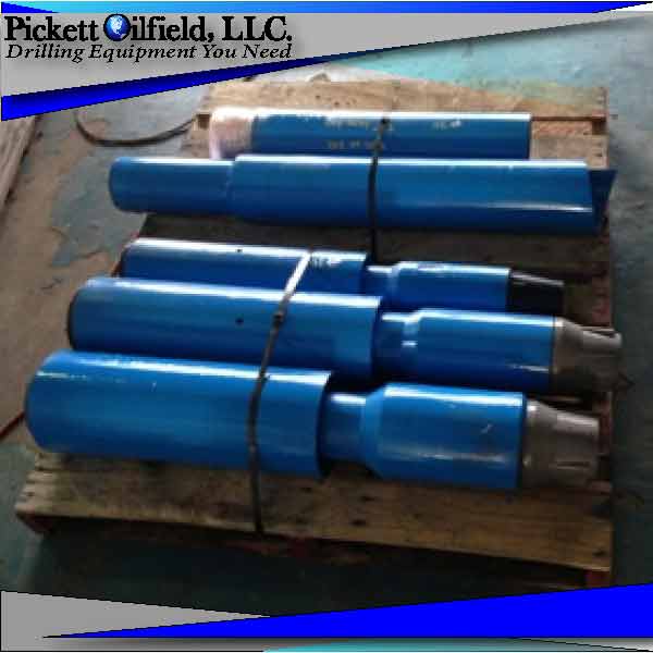
You are viewing Bowen or Logan Overshots for sale by Pickett Oilfield, LLC. We have an extensive range of good used or rebuilt Overshots along with the accessories. Call us for your fishing tool needs. For more information contact us by phone at sales@pickettoilfield.com.
PickettOilfield.com offers prospective buyers an extensive selection of quality new, used, and refurbished Oilfield Equipment at competitive prices, including Overshots.
Overshots are a tool used on the downhole process during the fishing operations. It engages the tube or tool on the outside surface. A Grapple or other piece of equipment that is similar attaches onto the overshot and grabs the fish.
Explore the various drilling overshot products available for wholesale at Alibaba.com. Get a drilling overshot for drilling water wells, water exploration holes, geological exploration, coal mines, and other kinds of mining. Some drilling overshot options use caterpillar tread to move. Others use rubber tires, while others require a separate means of transport. Caterpillar tread propulsion can climb up to 25 degrees inclination. Some products in the range are capable of drilling over 200 meters, while others are only used for open-pit mining with depths of around 3 meters. Drilling can be done vertically downwards, horizontally, or in a slanting direction. Drilling speed depends on the power of the machine and the general hardness of the surface. The hole diameter can vary from 90mm to 200mm.
drilling overshot options also include an air compressor, a mud pump, drilling rods of various sizes, connectors, and a drilling tower. Drilling is done using drill bits of various shapes, sizes, and compositions. You can choose between diamond bits, alloy ring-shaped bits, 3-wing alloy bits, PDC bits, and hammer bits. Each drill bit uses different drilling methods, including rotary, percussion, blast hole, and core drilling.
Smaller products have a lifting power of around 25 kilonewtons and weigh about 2,500kgs. They’re ideal for small-scale drillings such as farms and homes. Larger ones are faster with more power, making them ideal for commercial use. Browse through Alibaba.com and find a drilling overshot that’s ideal for your work scope. Buy mine drilling rigs for your wholesale business at competitive prices. Chinese wholesalers provide you with customization options and great after-sales services.
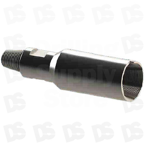
This drilling tool is an Over shot fishing tool. To construct this part it we manufacture in a similar fashion to the fishing spear. The over shot is precision CNC machined from hardened high alloy steel. And has a sharp internal thread profile. This fishing tool latches to the outside diameter of the broken down hole drilling tool. The hard sharpened threads are designed to latch and thread into the part.
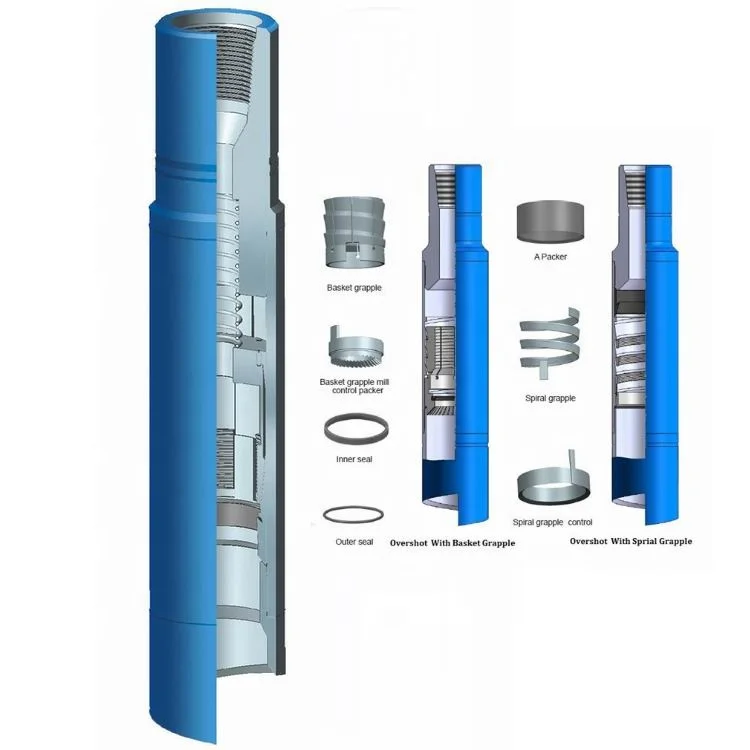
The slip overshot is an unreleased tool designed to externally engage a fish .It not only can engage every kinds of oil tube, drill pipe, weight rod, long plumb but also can reverse the stuck pipe string by giving torque to the stuck pipe string
PARVEEN Wireline Overshots are used retrieve a fish lost in the well that does not have a conventional fishing neck or a damaged fishing neck on it. The tool is operated by applying the weight of the tool string on to the fish. This will allow the slips to expand around the fish when the tool string is picked up, the slip will engage the fish. These are non releasable type overshots.
And I know about this "Honey I dropped the Pump" problem too, and haven"t added a full article on retrieving stuff from water wells at InspectAPedia because of lack of photos of the array of in-well-stuff grabbing tools, and also because I don"t think most homeowners will have much luck retrieving stuff that has fallen into their well on their own.
Augers are drill-type devices designed to retrieve drill components from a borehole by drilling into a verical (dropped) pipe or by wrapping around it.
Magnets or junk magnets, are sometimes used to retrieve smaller metal objects that have fallen into a well; it"s doubtful that a magnet could pull a steel well pipe however. In the oil and gas industry junk magnets are run into a well ahead of a diamond drilling tool in order to remove metal junk that can damage the drilling bit.
Overshoots or Overshots are fishing devices that fit over the exterior of the well pipe and then grab onto the well pipe exterior to enable lifting the pipe.
Logan Oil Tools calls these "external catch" devices. [12] The overshot may be a metal mesh device, or a spiral device, one or more round or oval loops, or similar devices that grab on to the pipe exterior. The overshot was invented by Bowen in 1935.
Logan Oil Tools calls devices of this sort "internal catch" devices.[12] Releasing spears include design features that can when appropriate release the "caught" pipe or component. Spearing tools are used to retrieve piping from a well when it cannot be grasped with an external catch tool.
See WELL FISH TOOL & CAMERA SOURCES at the end of this article for manufacturers of well retrieval tools, well pipe retrievers, well pump retrievers, specialty well repair tools, and for patented designs that suggest home made well pipe retrieval tools.
Basket types, other: Core-type junk baskets retrieve junk from the bottom of a well by literally drilling a hole into the debris so that it can be removed.
Boot baskets are used in oil and gas drilling to catch debris below the bit that are too heavy to be circulated out of the bore hole during the drilling procedure.
Jars or bumper tools are designed to impact stuck pipes, spears or other components stuck in a well by hydraulically jarring the stuck component upwards or downwards.
Box Tap / Die Collar, used to retrieve tubular fish tools that can"t be rotated. This is a special type of overshoot used to connect to the top of tubing or piing. See Overshoots below. Produced by Schlaumberger and others.
Casing Swage is a tapered tool used to restore dented or collapsed well casings to approximate its original shape. Note that these tools will not repair a casing that has been broken or corroded through. Well sleeves or casing section replacement is needed in those cases. Speaking strictly this is a casing repair tool not a well retrieval / fishing tool.
I"m doubtful this tool is able to grab a round well pipe (the maximum length is about six feet and the end looks like suction cups) but the company may have tool ends that can be adapted for that purpose.
Pipes in oil and gas drilling become stuck in wells differently from what happens in a drilled water-well or borehole well, but some of the tools developed for the oil and gas industry may also benefit the water well drilling and well retrival tool industry.
The traditional freepoint tool is an electromechanical tool designed to measure the amount of torque or stretch of a given length of tubing, drill pipe, or casing. The traditional freepoint tool uses either bow springs or magnets to anchor itself inside the pipe.
After obtaining an estimate of the free point by using the pipe stretch estimate technique, the traditional freepoint tool is run in the hole to 1000 feet above the estimated stuck point. The tool is anchored in place. Stretch and or torque is then applied to the pipe.
The tool is then run roughly 500 feet past the estimated stuck point. Stretch and torque are applied, and readings are taken. If the tool indicates that the pipe is stuck at that point the tool is pulled uphole and readings are taken again.
The Halliburton Freepoint Tool is based around the magnetorestrictive property of steel. This principle states that when torque or stretch is applied to free pipe, the magnetization will change. Stuck pipe will have no change in magnetization. There is a magnet on the bottom of the tool that creates a small magnetic field.
There are four co-planar orthogonal multi-axis high sensitivity magnetometers located above the magnet. The magnetometers measure the change in the magnetization of the pipe. The pipe is set at neutral weight, then the tool is run downhole logging the entire pipe string. Once it is at the bottom of the string, torque or stretch is applied to the pipe.
The tool is then pulled uphole logging the entire string. The tool will detect differences in the magnetization of the pipe, thereby indicating free and stuck sections of pipe. - Wikipedia, retrieved 2016/05/31, original source: https://en.wikipedia.org/wiki/Pipe_recovery_operations
Pull slowly and smoothly and as soon as you can mechanically grab the end of the lost pipe as it emerges from the well, do so. The pipe tongs shown below, provided by Hole Products (cited below) are used to grip pipe for hoisting; this tool will automatically release the pipe when tension is released on the lift line.
Hydraulic Fishing Jars are tools lowered into a well that grasp onto the stuck pipe, fish, or component to permit freeing a stuck component by jarring it upwards or in some applications downwards or in either direction. (Schlumberger) Fishing jars are also referred to as fishing accelerators.
Magnets for use in a well bore: Hole Products and other well service companies produce powerful magnets that can be lowered into a well to retrieve tools or metal pieces of irregular shape that have fallen into a well and that can"t be grabbed by other tools shown here.
Shown below, a well magnet fishing tool set provided by Hole Products Company whose contact information is given below in this article. Depending on the magnet size these devices can lift 100 to 400 pounds. The largest magnet shown below is 5 1/2" in diameter so may fit inside a 6" well casing.
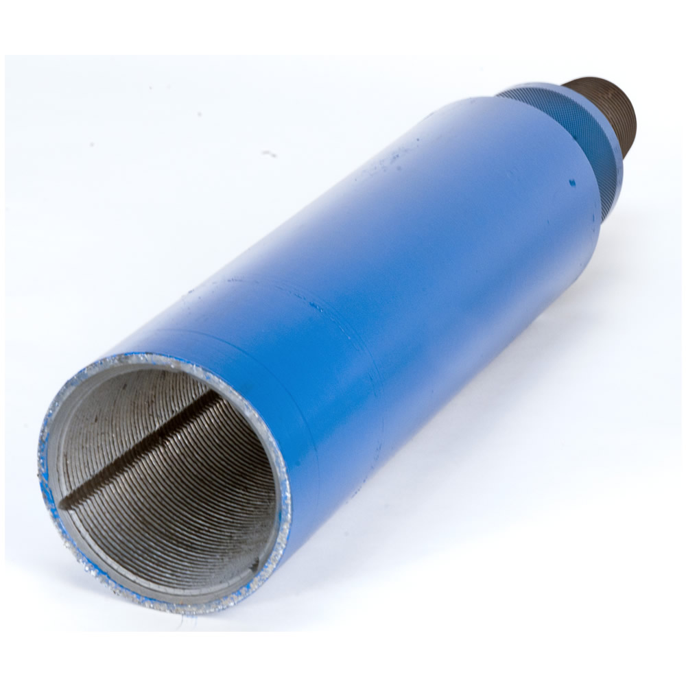
Overshot mesh well pipe or item retrievers for fishing stuff out of a well: the most effective tools we know about for pulling lost well pipes out of a drilled well are various versions of overshots. Overshots, an "overshoot" type tool, are a bit easier to get over the outside of a well pipe than spear type tools are to get into the well pipe, unless the upper end of the pipe is near the top of the well.
Some supplies use the term "recovery bell" for overshots. The overshot is a cylindrical or conical shaped (bell shaped) device lowered over the upper end of a pipe to be retrieved from a well. Some companies (Schlumberger) produce a releasing overshot or overshots used for jarring or stuck material backoff operations.
The overshot is lowered over the end of the pipe in the well. If there is enough friction around the object the braided sleeve will contract and grab the object when the line is pulled up - like that braided rush "chinese finger trap" trick we played with as kids.
The overshot is attached to the end of a drilling rod or in the water well industry to the end of a section of well piping that is lowerd into the bore hole.
Some overshots include hardened self-cutting threads that will grab onto the upper end of a well pipe that has been dropped into the well borehole, thus allowing the pipe to be retrieved.
Pin Tap / Screw-In Sub taps are used to retrieve a tubular fishing tool or pipe from a well when it is cannot be rotated. Basically this is similar to a "screw extractor" that is reverse-threaded to be turned into a seized bolt, screw, or in this case pipe or fishing tubular tool that cannot be turned or rotated in its normal direction. Produced by Schlumberger and perhaps others. Also see Taper Tap.
PVC Well Casing Elevators: a special clamp-on elevator tool is required to lift a PVC casing or casing liner without breaking it. The tool shown below is provided by Hole Products whose contact information is given below in this article.
Releasing spear well retrieval tools: a releasing spear is a well pipe or tubing retrieval tool that includes an internal catch that retrieves pipes or tubing from a well bore. The releasing spear is lowered into the well where it "spears" the interior of the pipe to be retrieved. Bowen® Itco is a producer of releasing spears.
Taper Taps are produced by Produced by Schlumberger (shown above), Hole Products, and perhaps others. Hole Products also supply sonic taper taps sued to retrieve lost sonic tooling. Contact information for these companies is given below. Similar tools include packer milling and retrieving tools designed to drill through plugs in a well bore.
Washover shoes, (shown above) strictly speaking are not retrieval tools but rather devices that are used to free pipe that has been stuck or lodged in a well bore due to fallen debris or other obstructions.
Watch out: when buying or fabricating a tool to pull a dropped well pipe or something else out of a well, be careful not to drop your new tool into the well alongside what"s already in there. Test your device above ground first and also be sure it"s strong enough and long enough to do the job.
Note that the primary producers of well retrieval and fishing tools are companies serving oil and gas drilling industry companies. However many of these also serve the water well drilling industry too.
Check with your local well driller as those folks will have more experience, retrieval tools, and probably safer procedures than a normal property owner. The savings in time and money by hiring a professional may be more than you first guess.
Bowen Itco, owned by NOV since 2000, produces well fishing tools, devices, equipment including the Bowen™ Itco-Type Releasing Spear . The company"s website provides no street address but includes a contact page, Website: http://www.nov.com/bowen/default.aspx
Belle Plaine, KS 67013 USA, Dapalco produces the Fetch well pipe retrieving tool. Website: http://www.dapalco.net/ or www.thefetch.net Tel: 866-397-7347 Email: aprinter@sktc.net
This pipe fishing tool uses a jaw with two tips and a center slot. One leg of the jaw slips into the upper end of a cut-off pipe inside the well and jaw teeth grip the pipe wall to permit lifting it. Lifting capacity: 250 lbs. U.S. Patent No. 7,665,785
A catch tool for retrieval of a well column pipe having a pipe wall, the catch tool incorporating a fork having a pair of spaced tines; and a pair of clamping pivot arms connected operatively to the fork, the clamping arms being adapted for, upon the receipt by the tines of the pipe wall, grasping the pipe wall;
Gotco Corp., 11410 Spring Cypress Rd., Tomball TX 77377 USA, Tel: 1-800-OVERSHOT, produces the Gotco Grapple Releasing Spear. Except from the company"s website:
Schlumberger Fishing Tools and Services, 3750 Briarpark Dr., WG-3 Level-2, Houston TX 77042, produces a wide range of oil and gas drilling tools and equipment and opeates world-wide. North American Contact: Schlumberger Technology Corporation
Stuckey"s Specialty Tools, Fishing Tools & Specialized Equipment, 2511 Lauder Road, Houston, Texas 77039, E-Mail: stusptl@yahoo.com Website: http://www.stuckeyspecialtytools.com/ producing an Itco type releasing spear
EvCam provides a variety of downwell and well bore inspection cameras that can help identify well obstructions and dropped objects to combine with a wellbore fish tool to retrieve dropped materials from a well.
You"re quite right that the first business in providing water from a deep well is to drill the well - that"s not something that a person can do; it requires drilling equipment;
I don"t have comment to you because is my first time to see some of fishing tools and the quality are good but my humble request is how can a pump machine like me who can"t afford to get or buy can manage to have it.
Century Foundation Company that posted before we are one in the same. If interested in seeing this tool it is for sale call number or email centuryfoundationcompany@gmail.com
I have a tool I made in my machine shop that will go get ANYTHING in a water well or oil well no difference not like the stuff shown here. Drop a pipe wrench in the hole I will have it back in 5 minuets guarantee. 93sixsevenone 8 one three two 5
You are welcome to post a photo of your tool here and if you use the page top CONTACT link we can look at your info for addition to sources of well pipe grabbing tools in this article series.
. It will go any distance bring back anything. It will retrieve and bring it back in about 10 minutes. There is only one of theses tools in the world and I made it. I can make one for any size Id pipe. If you need one contact me. Century Foundation Company magnolia Texas is on net.
When you lower a well cam you can see if there is a rope or pipe that"s likely to be able to be grabbed by one of the retrieval tools we illustrate; you basically have to match the tool to the space available, to what"s in the well, and to the position of the fallen materials.
Aside from the dropped well pump or pipe tools shown in our article above, I"ve read that some well pump retrieval projects had success by trying a piton or crevice clamp (mountaineering equipment) or even a simple small grappling hook that snagged a dropped well rope.
finally got to the bottom and the water pump wasn"t at the end of the pipe.... the wires had somehow been severed and I"m not sure how or why it happened but I need advise on tools that I could use or make to use to grab onto the piece of pipe and pump that is still sitting at the bottom of our deep well.
I lost a section of pipe and a tool in my well trying to pull out what was dropped in by a previous well company. The pull line broke. Can I just leave it there?
It"s probably possible to retrieve the ring, though it"ll be some trouble. Check with your well driller to see what small-object retrieval tools they have on hand. There are two approaches:
3. a jet-venturi system used in oil drilling rigs and possibly some well operations can also retrieve small objects but I"d be careful about using this approach as if the bottom of your well has inches thick sediment we don"t want to risk pushing the ring deeper into the sediment.
Fair question, Tina but prices are all over the place depending on the particular pipe grabber tool and its appilcation, from $10. to $1000 or more. The "Fetch" pipe spear described in the article above retails for about $500. U.S.
Other readers: Mr. Myers reference to a "slip tooth" probably refers to an anchoring mechanism for a well tool that allows for movement in directions other than straight vertical.
The most expert deep well drillers in the world come from the oil and gas fields. One of their approaches for tool jams such as the one you describe, if a grabbing tool can"t remove the fallen object, is to drill through it.
I got an old shallow well and my inner pipe is a inch and a quarter inside the case and the top three threads broke off when was trying to pull it out what kind of tool do I need to get that inner pipe out and where can I find it
While I like a pipe spear for the situation you describe, most of the well pipe grabbers described in the article above or a home-made version of one of them ought to work; to save time and trouble give your local well drilling contarctor a call as they probably have several of these tools at hand plus the lift or winch needed.
WELL RETRIEVAL TOOLS at InspectApedia.com - online encyclopedia of building & environmental inspection, testing, diagnosis, repair, & problem prevention advice.
[11] "Overshot Definition", OilGasGlossary.com. Oil & Gas Field Technical Terms Glossary, Web Search 04/21/2012, original source: http://oilgasglossary.com/overshot.html

There are a number of problems that can occur while drilling a well. Whether a drillstring breaks and falls to the bottom of the wellbore or a bit breaks, accidents happen. Even pipe or a tool can fall from the rig floor into the bottom of the well.
In order to perform fishing on a well, drilling must be shelved and special fishing tools employed. Each tool is specially crafted to perform a specific function, or retrieve a certain type of fish. Most fishing tools are screwed into the end of a fishing string, similar to drillpipe, and lowered into the well.
There are two options to recover lost pipe. The first is a spear, which fits within the pipe and then grips the pipe from the inside. On the other hand, an overshoot may be employed, and this tool surrounds the pipe and grips it from the outside to carry it up the wellbore.
When a fish is difficult to grip, a washover pipe or washpipe is used. Made of large-diameter pipe with a cutting surface at the tip, washpipe is run in the well and then the cutting edge grinds the fish to a smooth surface. Then drilling fluids are pumped into the well to remove debris, and another tool is used to retrieve the remaining fish.
Sometimes, a junk mill and boot basket are used to retrieve fish from the wellbore. In this instance, a junk mill is lowered into the well and rotated to grind the fish into smaller pieces. A boot basket, also known as a junk basket, is then lowered into the well. Drilling fluid is pumped into the well, and the ground parts of the fish are raised into the basket and then to the surface by the boot basket.
In order to recover casing that has collapsed within the well or irregularly shaped fish, a tapered mill reamer can be used. Permanent and magnetic magnets are employed to reclaim magnetic fish, and a wireline spear uses hooks and barb to clasp broken wireline. Additionally, an explosive might be detonated within the well to break the fish up into smaller pieces, and then a tool such as a junk bucket is used to retrieve the smaller items.
When a fishing professional is unable to determine which fishing tool might work best to retrieve the fish, an impression block is used to get an impression of the fish and allow the professional to know with what exactly he or she is dealing.
Fishing a well may take days to complete, and during this time, drilling cannot occur, although the operator is still responsible for drilling fees. Some drilling contractors offer fishing insurance, making operators not responsible for rig fees during fishing operations.
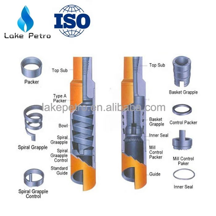
Mar032016OILWELL SUPPLIES: BASKET GRAPPLE FOR 4 9/16OD SLIM HOLE RH OVERSHOT 3-1/8 (4 NOS) 2-7/8 (4 NOS) 3-1/16 (2 NOS) 2-3/8United StatesBombay SeaUNT12525,12543,760
Mar032016OILWELL SUPPLIES: BASKET GRAPPLE FOR 4 9/16OD SLIM HOLE LH OVERSHOT 3-1/8 (5 NOS) 2-7/8 (5 NOS) 3-1/16 (3 NOS) 2-3/8United StatesBombay SeaUNT16841,79952,612
It’s the simplest fishing tool available for engaging a fish internally to catch drill pipes or drill collars. TO ENGAGE THE FISHIt is necessary only to run the taper tap in the hole to the top of the fish, apply less than one point of weight and rotate sufficiently to embed the tapered threads of […]
This is the simplest fishing tool for engaging a fish externally. TO ENGAGE THE FISHYou must ony run the die collar in the hole to the top of the fish, apply less than one point of weight and rotate sufficiently to embed the tapered threads of the die collar into the fish, cease rotation and […]
It’s the strongest tool available to externally engage, pack off and pull fish. During the engaging operation, the overshot is rotated to the right and upward pull is exerted. If the fish doesn’t come, circulating pumps may be started and drilling fluid forced through the fish. How to order-Specify:1) Hole size; 2) Size O.D. of […]
The TKM Casing Spear is a simple and effective tool used to recover pipes or screens in a well or to set a liner or screen at a certain depth. It is made up of heavy duty system needed to engage the inside o a pipe or screen, actriveted thru use of high pressure. The […]
The AD-CASING CUTTER is an hydraulic cutting tool for single casing operations at precise depth.The tool features 3 steel knives with TC HardColoy, positioned at 120°, that during the string lowering into the well are contained inside the recess in the cutter body. As soon as the depth is reached, the knives are pushed in […]
These tools dressed with hardcoloy, are used to mill objects lost inside the hole not retreviable with conventional methods. The milling tools may be redressed with Hardcoloy once they are worne out. How to order-Specify:1) Intended service; 2) Hole size; 3) Top connection
with Fishing Tool Manager for guidance. Consult with a EOFR Fishing Manager when requirements do not fall within the guide line shown; Bottom Hole Assemblies (BHA) also should be considered
Overshot Type* Grapple Maximum Catch Spiral Maximum Catch Basket Bowl Load Cap. at Yield Point (lbs)
Overshot Type* Grapple Maximum Catch Spiral Maximum Catch Basket Bowl Load Cap. at Yield Point (lbs)
Overshot Type* Grapple Maximum Catch Spiral Maximum Catch Basket Bowl Load Cap. at Yield Point (lbs)
Overshot Type* Grapple Maximum Catch Spiral Maximum Catch Basket Bowl Load Cap. at Yield Point (lbs)
Overshot Type* Grapple Maximum Catch Spiral Maximum Catch Basket Bowl Load Cap. at Yield Point (lbs)
Overshot O.D. .955 1-1/8 1.290 1-9/16 1.43 1-21/32 1-21/32 1-21/32 1-25/32 1-25/32 1-25/32 1-29/32 1 29/32 1-29/32 1-29/32 1-29/32
Overshot O.D. 2-5/16 2-5/16 2-5/16 1-27/32 1-27/32 1-27/32 2-1/16 2-1/8 2-5/16 2-5/16 2-5/16 2-1/4 2-1/4 2-1/4 2-5/16
Overshot O.D. 1-1/4 1-3/8 1-1/2 1-5/8 1-3/4 1-3/4 1-27/32 1 15/16
Overshot O.D. 1-27/32 1-29/32 2-5/16 2-1/4 2-5/16 2-5/16 2-25/32 2-7/8 2-7/8 3-1/8 3-1/4 3-3/8
WARNING! All jarring and pulling loads shown in the manual assume that the force is acting alone and is essentially along with major axis of the tool. If
Users of jars and bumper subs should be aware that milling or drilling operations may develop stresses in these tools that are more complex than the simple torsional and tensile values
Weatherford Fishing Tool Manual 83
Tool Joint 1-1/4 Reg. 2-3/8 Reg. 2-3/6 EUE 2-3/8 I.F. 2-7/8 I.F. 3-1/2 I.F. 3-1/2 I.F. 4-1/2 FH 4-1/2 FH 5-1/2 Reg. 6-5/8 Reg.
Tool length (ft) 9-1/2 9-1/2 9-1/2 9 9 10 10 9-1/2 12 11 12
MAXIMUM TOOL I.D. 1 1-9/16 1-15/16 2-1/2 2-3/16 2-15/16 3-1/2 3-1/2 4-1/2 4-1/2 5-1/2
OVERSHOT O.D. 3-1/8 3-3/4 4 4 4-1/2 4-1/2 4-1/2
OVERSHOT O.D. 4-1/2 5 4-11/16 5-1/2 5-1/2 5-1/2 6-1/8

Tianhe Oil Group Co. Ltd. is a global group. We are specialized in the production of drilling tools, including R&D, production, selling, leasing, maintenance and services. Tianhe has 5 main businesses spread across the globe in more than 50 countries in the world.

In U.S. Pat. No. 3,120,283 to Braun there is disclosed a core barrel inner tube assembly having an overshot coupling portion retained in a position by the latches in their retracted position to prevent fluid bypass until the latches move to their seated position and thence under gravity or inward fluid pressure move to permit fluid bypass and prevent the latches moving to their retracted position until the coupling portion is retracted; and a fluidly propellable overshot assembly. Also it is old to provide a core barrel inner tube assembly that is similar to that of the second embodiment of U.S. Pat. No. 3,333,647 to Karich except that the spearpoint plug has an annular fluid seal member with a bypass channel that includes an outer port opening outwardly of the seal member and an inner port that is blocked by the latch release tube when the plug is in its inner position relative to the tube, and resilient means to urge the release tube inwardly relative to the latch body to the release position. The plug is mechanically forced to its bypass open position when the release tube moves inwardly.
U.S. Pat. No. 3,266,835 to Hall discloses a core barrel inner tube assembly fluidly propellable in any direction and includes a valve assembly connected to a spearhead and resiliently urged to a position to block fluid flow. When the inner tube assembly moves to its inner position, water pressure forces the spearhead assembly to move to open a bypass channel and allow the latches to move to a latch seated position. If the latches do not seat properly a valve is not opened and bypass is blocked. French Patent No. 2,014,485 discloses a first embodiment of a latch that has an axial outer hook portion for couplingly engaging an overshot assembly and an inner hook portion extending transversely in the opposite direction from that of the hook portion for coupling engaging a latch seat while the second embodiment has an outer hook portion for couplingly engaging an overshot assembly and an outer portion for engaging a latch seat, both of which are outwardly of the latch pivot. U.S. Pat. No. 3,701,389 to Egnelov et al also discloses some of the same structure as disclosed in the French patent. U.S. Pat. No. 1,427,268 to Dodd discloses outer latches to block outer movement of the core barrel inner tube assembly and inner latches to block inward movement when in the core collecting position.
A core barrel inner tube assembly that includes a latch body portion pivotally mounting a latch for movement between a retracted position and a latch seated position, an axially elongated portion extending axially relative to the latch body portion for defining a fluid bypass channel, valving mechanism extending within the channel that is movable between a first position substantially blocking inward flow through the channel and a second position providing a fully open fluid channel, valve control mechanism that is movable relative to the latch body and elongated portion for moving the valving mechanism from the valving mechanism second position after the latch has moved from its retracted position to its latch seated position with the assembly at the bit end of a drill string and inward fluid pressure has been significantly decreased from that previously applied. In one embodiment the valving mechanism is at least in part retained in its first position by the valve control moving mechanism which in turn is prevented from moving the valving mechanism by abutting against the latch in the latch retracted position. In another embodiment the valving mechanism and the elongated portion are of a construction that the valving mechanism is moved inwardly from a fluid channel open position to the valving mechanism blocking position by inward fluid flow when the bore hole extends upwardly in an inward direction. Advantageously the last mentioned embodiment has a latch with an overshot hooking portion and a foot on the opposite axial side of a latch pivot to extend transversely outwardly in the same direction with the foot being abuttable against the valve control mechanism to prevent the valve control mechanism moving the valving mechanism to its second position until the latch moves from its retracted position to the latch seated position.
One of the objects of this invention is to provide a new and novel core barrel inner tube assembly that requires its latch moving to its latch seated position and a substantial decrease of inward fluid pressure applied to the assembly before a fluid bypass channel fully opens for inward bypass fluid flow. In furtherance of the above object, it is another object of this invention to provide an assembly that is fluidly propellable inwardly regardless of the direction of extension of the bore hole. Another object of this invention is to provide in a core barrel assembly new and novel means for blocking inward fluid bypass until the assembly latch means moves to its latch seated position and retains the latch means in the latch means seated position until the assembly is retracted by an overshot device.
FIGS. 1-4 when arranged with their axial center lines aligned and lines A--A of FIGS. 1, 2 aligned; lines B--B of FIGS. 2, 3 aligned; and lines C--C of FIGS. 3, 4 aligned, form a composite longitudinal view through the first embodiment of the core barrel inner tube assembly of this invention with portions of the drill string and longitudinal spaced portions of FIG. 4 being broken away, said view showing the inner tube assembly in its latched core drilling position and being generally taken along the line and in the direction of the arrows 1--1 of FIG. 10;
FIGS. 5 and 6 when arranged with their axial center lines aligned and lines D--D aligned form a composite longitudinal view through an overshot assembly and the outer end portion of the core barrel inner tube assembly of FIG. 1 other than the inner tube assembly is shown in its retrieval position just after the latches have been retracted;
The inner end portion of the drill string is commonly referred to as a corr barrel outer tube assembly, generally designated 12; the core barrel outer tube assembly being provided for receiving and retaining the core barrel inner tube assembly, generally 15. Details of the construction of the core barrel outer tube assembly of the general nature used in this invention may be such as that disclosed in U.S. Pat. Nos. 3,120,282 and 3,120,283. The core barrel outer tube assembly 12 is composed of a core barrel outer tube 18, a reaming shell 19 threadedly connected to the inner end of the tube 18 and an annular drill bit 11 for drilling into the earth formation from which the core sample is taken, said bit being threadedly connected to the inner end of the reaming shell. The outer end of the assembly 12 includes a locking coupling 20 which connects the assembly 12 to the adjacent pipe section of the drill string. At the opposite end of the coupling 20 from the above mentioned pipe section, an adaptor coupling 21 is connected. The inner end of the locking coupling in conjunction with the annular recess 21a of the coupling 21 form a seat inside of the surface of the adaptor couping against which the outer latches (detent members) 16a, 16b of the core barrel inner tube assembly are seated for removably retaining the assembly 15 adjacent to the core bit. The inner end portion of the locking coupling may have a projection flange to bear against the face of a latch to cause the latches and other portions of the core barrel inner tube assembly to rotate with the drill string when the latches are in a latch seated position such as indicated in FIG. 1.
The latch axially elongated outer parts 38 are integrally joined to feet 37 which extend further radially outwardly relative the central axis M-M of the inner tube assembly than the axially adjacent parts of parts 38. The parts 38 are integrally joined to axially elongated latch intermediate portion to form radial outward, downwardly facing shoulders 40. Integrally joined to the outer ends of portions 39 are radially narrow neck parts 36 of latch outer portions 35, 36 that are of radial dimensions substantially smaller radial dimensions than portions 39 whereby portions 39 have radial and axial outer corner portions seatable in the recess 21a in abutting relationship to the inner edge of the lock coupling. Latch outer end portions 35, 36 include overshot engagable end (hook) parts 35 that are integrally joined to the outer ends of parts 36 and are of grater radial dimensions than parts 36 to form radial outer, inwardly facing shoulders 43. Parts 35 have axial beveled edges 35a that radially diverge in an axial inward direction. Parts 35 are located in the outer end portion of slots 27 and extend further radially outwardly of the central axis M--M than parts 36. Hardsurface parts 29b are provided on parts 29.
As may be seen from FIGS. 1 and 12, the outer portion of head 30a has an outer frustoconcial part which has an inner major base that is of at least substantially the same dimension as the minimum spacing of edges 35a when the latches are in an extended positon to facilitate the overshot assembly, generally designated 44 (FIGS. 1, 5 and 6) couplingly engaging the latches when the overshot assembly is moved inwardly relative to the latches and the latches are in their latch seated position.
The tubular member main body 55a also has diametrically opposed, axially elongated slots 62 adjacent to the outer end of the main body. The latch feet 37 are extended into the slots during the time the inner tube assembly is being retracted, while when the latches are in their latch seated extended position and the inner tube assembly is in its drilling position the feet are located within the tube and inwardly of the slots 62 to abut against the main body 55a to prevent the latches being retracted out of the latch recess until after the tubular member 55 is moved inwardly relative to the latch body. Further the tubular member 55 has an axially elongated slot 48 opening for a grease fitting (not shown) on the latch body for piston portion 51b.
The tubular member also includes a pair of diametric opposed legs 55b extending outwardly of the main body 55a that are of the same inner and outer diameters as the main body to form outwardly opening slots to have the latches extend transversely outwardly therethrough. The legs are of axial lengths that when the inner tube assembly is in its core drilling position with the bypass channel open, their axial outer treminal edges are located a short distance outwardly of the latches in their latch seated position.
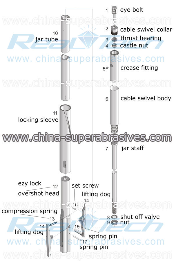
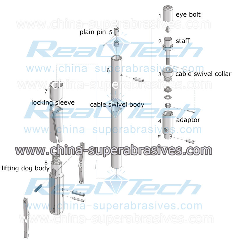
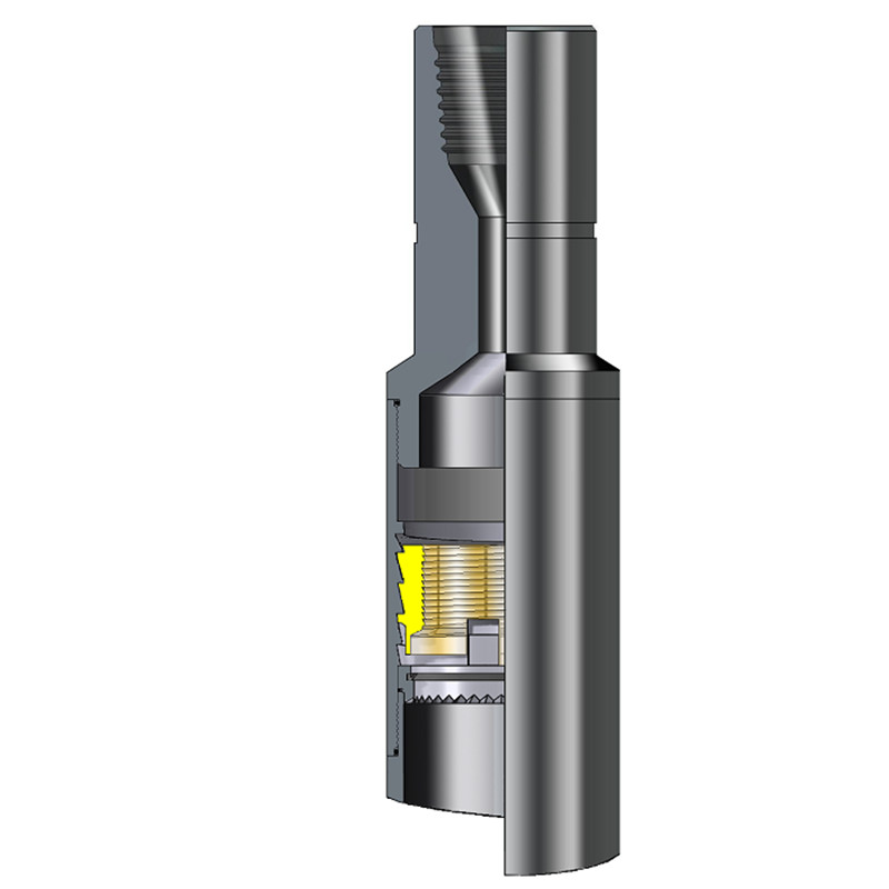
Referring to FIGS. 5 and 6, the overshot assembly, generally 81, that may be used to retract the first embodiment of the inner tube assemble, includes a swivel subassembly 82 to which the wire line cable 80 is attached. The subassembly is threadedly mounted by the outer end of the overshot body 83, the intermediate portion of which has an axially elongated bore 84 that at one end opens through ports 85 exterior of the body 83 and at the inner end opens through inner ports 86 exterior of the reduced diameter, inner end portion of the body. A resilient shut off valve 87 is retained in abutting relationship to an axially inwardly facing shoulder of body 83 by adjusting nuts 88 threaded on the body reduced diameter portion. The shut off valve forms a close fit with the inner peripheral wall of the drill string with ports 85, 86 and bore 84 forming a bypass channel that opens on axially opposite sides of the shut off valve and nuts 88. O-rings 89 are mounted in annular grooves on axially opposite sides of ports 86.
The overshot body is provided with axially elongated slots 90 inwardly of ports 86 into which a transverse pin 93 is slidably extended. A latch coupling tube 98 is slidably extended over the reduced diameter inner end portion of the overshot body, the tube mounting the pin 93 in a fixed position relative thereto. A compression spring 94 has one end abutting against pin 93 and an opposite end abutting against a set screw 95 threaded into the inner end of bore 96 to, through pin 93, resiliently urge the coupling tube outwardly relative to the overshot body. The axial movement of the coupling tube relative to the overshot body in one direction is limited to a position ports 86 are unblocked by the pin 83 abutting against the inner ends of slots 90, and in the opposite direction to a position ports 86 are blocked by the coupling tube with the pin abutting against the opposite ends of the slots. The coupling tube has an internal flange 98a providing an outwardly facing shoulder 100 and a bore 98b that opens to bore 98c and of a diameter that is sufficiently great to have the latch body part 30a pass therethrough.
If the valving mechanism is located such that it is in a fluid channel fully open position with the pin abutting against the outer ends of slots 49, upon pumping fluid under pressure into the drill string, pressurized fluid enters through the latch body slot 27 and acts against the outer end of the valve portion 51a and fluid flowing through the clearance space 61 and slots 49 to act against the inner terminal end of valve portion 51b and through passage 52, 53 to act against the annular surface at the juncture of valve portions 51a, 51b provides a pressure differential to move the valve member 51 inwardly to block the bypass channel 49, 54, 47, 68, 69, or if the drilling direction is downwardly can move under gravity to block the bypass channel. The inward movement of the valving mechanism is limited by the pin 50 abutting against the inner ends of slots 60.
Even upon the inner tube assembly moving inwardly to have the landing shoulder 64 seating on the landing ring, the latches are prevented from moving to their latch seated position due to the angles of inclination of the abuttable edges of the latches and the tubular member main body. Thus if the assembly is pumped inwardly a high pressure signal is provided at the drilling rig surface when the assembly seats on the landing ring or becomes jammed in the drill string. Similarly if the assembly is allowed to free fall under gravity to the bit end of the drill string, the valving mechanism moves outwardly relative to the latch body to open the bypass channel and upon the stopping of the inward movement of the assembly the valving mechanism closes to block the fluid bypass channel, and after sufficient time has elapsed for the assembly to seat on the landing ring, fluid is pumped in and a high pressure signal is provided at the surface.
When the inner tube is filled with core the shut off member 71b is squeezed to expand radially to provide a high pressure signal at the surface as is conventional, member 71b being a part of the spindle assembly 71. The overshot assembly 44 or another appropriate overshot assembly is inserted into the drill string and pumped inwardly. As the overshot assembly is pumped inward the spring 94 retains the coupling tube 98 relative to the overshot body to block ports 86 and in conjunction with valve member 87 prevents any significant inward fluid flow past the overshot assembly. Of course if the drilling direction is downwardly, a non-fluidly propellable overshot assembly having an inner end such as shown in FIG. 6 can be used.
Due to the inner diameter of the tubular member legs 55b being greater than the maximum diameter of the overshot bore portion 96a and less than the outer diameter of the coupling member, as the flange 98 passes inwardly of latch body head part 30a, the flange abuts against the legs to move the tubular member 55 inwardly relative to the latch body and against the resilient force of spring 56 sufficiently the latch feet are movable into the slots 62. Thereafter the flange abuts against the beveled surface 44a of the latches to move the latches from their latch seated position. Upon the flange moving inwardly of latch portions 35, the outer ends of the latches are spring urged away from one another such that shoulders 43 are at least in part directly axially outwardly of annular shoulder 100 of the flange. The inward movement of the overshot assembly is limited by the flange 98a abutting against the outer, generally transverse edges of latch parts 39. While the tubular member is moved inwardly and the latch portions are moved toward one another, the latch feet 37 move into slots 62.
Now upon retracting the overshot assembly the overshot body is moved relative to the coupling tube to open the overshot bypass channel. Thence the coupling tube is retracted, the latch body being retracted therewith. The feet in extending into slots 62 prevent the tubular member moving inwardly relative to the latch sufficiently to permit the valving mechanism moving to fully block the bypass channel of the inner tube assembly.
The structure of the second embodiment of the invention having been described, the use thereof will now be set forth. When the inner tube assembly is outside of the drill string and the outer latches are in their extended (latch seated) position, a suitable tool, for example a rod with a hole in one end to have the pin to extend thereinto, is forced inwardly and circumferentially into slot legs 200, provided the pin is not located in leg 200. The piston is then retained in such a position by spring 205 which exerts a spring force greater than that of spring 208. At this time the piston and spring 214 act to retain the valve ball outwardly of bore portion 191a to block fluid flow axially inwardly of the ball and thus the fluid bypass channel 211, 191, 217 is blocked.
When the core barrel inner tube assembly has moved inwardly to a position the inner latches 162a, 162b are radially adjacent to the drill string latch seat, the inner latches move to their latch seated position and upon abutting against the landing ring a high pressure signal is provided at the drilling surface. When in the last mentioned position, the outer latches are free to and are resiliently moved to their latch seat position, it being noted that when the pin 171 abuts against inner end portion 175 of the latches the inner wall portions that in part defining the slots 174 are located to permit the outer latches so moving. When both of the outer latches are in their latch seated position, the blocking pin 177 is free to move axially inwardly relative to the latch body between edges 175a and as a result of the action of spring 184 the release tube does move inwardly relative to the latch body. The inward movement of the latch release tube permits the cam pin 195 to move inwardly into the inner end of cam legs 197 and if the assembly is pumped in the fluid pressure on the valving mechanism is valving to move the piston and thereby the pin inwardly into the inner end of the legs 197, the ball 215 moves into bore portion 191a and allows a low rate of fluid bypass which will reduce the pressure at the surface. However the pressure signal does not reduce anywhere near the reduction that would take place if the fluid channel were fully open. In the event the inner tube assembly is allowed to free fall to the bit end of the bore hole, pin 195 does not move to the inner end of the cam slots until fluid is pumped into the drill string.
In the event the second embodiment should become jammed in the drill string outwardly of its core collecting position, or if one or both of the outer latches does not pivot sufficiently to abut against the inwardly facing shoulder that in part defines the latch seat, the latch release tube is prevented from moving inwardly relative to the latch body by the pin 177 abutting against the inner end portions 175 of the outer latches and accordingly the outer bypass channel remains blocked for inward fluid flow and a high pressure signal is provided at the drilling surface.
After the core receiving tube is filled and the shut-off valve 158 is compressed to provide a pressure signal at the surface, a conventional wire line overshot assembly is pump-in or allowed to free fall, depending on the drilling direction and the drilling conditions. Upon the overshot assembly coupling onto spearpoint plug portion 207a, the initial retraction of the spearpoint plug through the cylinder tube retracts pin 189 to abut against the outer edges of the slots 190. Further retraction moves the latch release tube and thereby pin 177 to be axially inwardly of the outer latch portions 175. Thereupon the inner beveled edges that in part define slots 174 abut against the beveled edges of the outer portions of the outer latches to pivot the outer latches to their retracted position. After the outer latches have been retracted and pin 177 abuts against the outer ends of the latch body slots 178, further retraction of the overshot assembly results in pin 177 moving the latch body outwardly, and upon the outer diagonal edges 162c abutting against the axial outer edge of the latch seat, the latches 162a, 162b are pivoted to their retracted position. The outward movement of the latch body retracts the structure attached thereto and extending inwardly thereof.
During the time the overshot assembly moves toward the spearpoint subassembly and as it retracts the spearpoint subassembly the valve ball remains in the dotted line position of FIG. 13 so that the bypass channel remains open.
Even though the above two embodiments of the invention have been described with reference to a core receiving tube, core lifter and core lifter case, it is to be understood that in place thereof there may be provided on the inner end of the core barrel inner tube assembly, another type of tool, for example a plug bit or other type of drill bit in the event it was not desired to collect a core sample.
The piston spring 236 gives a force great enough to move the the piston inwardly to its fluid channel blocking position regardless of the pump-in pressure or pump-in flow rares and the drilling direction except for one of the conditions as follows:


 8613371530291