
overshot loader manufacturer

The Rocker Shovel Loader 12B provided a significant boost to underground mining productivity by emulating the movements of the human "mucker," the laborer who removed rubble, or "muck," from underground mines, particularly in and narrow mine tunnels. Designed in the late 1930s by Edwin Burt Royle and John Spence Finlay, employees of the Anaconda Mining Company, the first working machine was called an "overshot loader." Both men worked for the North Lilly Mine in Ureka, Utah, in the 1920s and early 1930s. Apparently prior to 1931, their machine had a heavy bucket attached to a rail car by two moveable rocker arms, and the car had air-motor powered wheels to push it into the rubble. In 1931, Joseph Rosenblatt of EIMCO, Salt Lake City, met Royle and Findlay, and shortly thereafter, Royle joined EIMCO as a consultant and designer. Where the first machine had been constructed from discarded Model T parts, EIMCO then developed it into the Model 12B that sold thousands.
The loader was operated by a worker at the side of the machine who could manipulate two controls, one for the wheels and the other for bucket travel. It was run entirely by compressed air. As the machine moved forward, the bucket (with an operating capacity of four to six cubic feet) was capable of removing up to 30 cubic feet of rubble per minute. When the bucket was full, an operator would actuate the bucket drive motor that would move the rubble upward and rearward into a mine car for removal.
Manufacturing rights were licensed to companies in Great Britain, India, South Africa and Japan. Sales expanded beyond the United States into Australia, Canada, Chile, France, Mexico, Spain, and Zambia. By 1969, 29,000 loaders had been sold. The loader in Park City is the same model used in the mine tunnels under Park City, some 1,200 miles (1931 kilometers) approximately. EIMCO Mining Machinery Intenational was sold around 1980 to the Sandvik Group (Sandvik AB), headquartered in Sandviken, Sweden under the name of Tamrock Loaders.

Overshot loaders, also known as overhead loaders, differ from conventional loading machines in that a work implement, typically a bucket, loads material from one end of the machine, e.g., the front, lifts the material over the top of the machine, and dumps the material from the other end of the machine, e.g., the rear.
Numerous examples can be found in the patent literature of overshot loaders, particularly during the 1940s, 1950s and 1960s. As a few examples, in U.S. Pat. No. 3,203,564, Brekelbaum et al. disclose a wheel loader which incorporates the overshot concept. Pueschner et al., in U.S. Pat. No. 2,936,086, disclose an overhead loader based on a tracked loading machine. Hoover elaborates on various features of overshot loaders in U.S. Pat. Nos. 2,427,968 and 2,529,338.
Overshot loaders during the above-mentioned period of time required human operators on board the machines. Thus, in virtually all cases, the load of material passing over the top of the machine also passed over the operator. As a consequence, overshot loaders never became popular in spite of the potential increase in productivity resulting from more efficient handling of the material being loaded and dumped. In fact, from the 1970s to the present, patent literature on overshot loaders have virtually disappeared, as well as the use or consideration of use of overshot loaders at all.
An overshot loader designed to operate autonomously, or at most by remote control, may be built without the constraints imposed by manual operation. Placement of the power and drive train, and function of the work linkages and work implement, may be designed for optimal productivity and efficiency. Thus, an overshot loader designed and built for non-manual operation has the potential for productivity rivaling much more expensive and massive machines, such as front shovels and large excavators.
In one aspect of the present invention an overshot loader is disclosed. The overshot loader includes a set of ground engaging members, a frame attached to the set of ground engaging members, and a linkage assembly movably connected to the frame and located within a longitudinal center portion of the frame.
In another aspect of the present invention a linkage assembly for an overshot loader is disclosed. The linkage assembly includes a boom having a first end pivotally connected to a frame and oriented substantially centered with and parallel to a longitudinal center portion of the frame, a stick having a first end pivotally connected to a second end of the boom, and a work implement pivotally connected to a second end of the stick.
In yet another aspect of the present invention an overshot loader is disclosed. The overshot loader includes a set of ground engaging members, a frame attached to the set of ground engaging members, a boom having a first end pivotally connected to the frame and oriented substantially centered with and parallel to a longitudinal center portion of the frame, a stick having a first end pivotally connected to a second end of the boom, a work implement pivotally connected to a second end of the stick, and at least one control link having a first end pivotally connected to the frame and a second end pivotally connected to the stick, wherein the frame defines a ground link of a first four bar linkage, the boom defines a power link of the first four bar linkage, a portion of the stick from a boom-to-stick connection point to a control link-to-stick connection point defines a coupler link of the first four bar linkage, and the control link defines a control link of the first four bar linkage.
The following paragraphs and the accompanying drawings and claims describe an overshot loader 100 for autonomous operation. It is noted that autonomous operation refers to unmanned operation; that is, the loader 100 is configured to operate without the direct interaction of a human operator. However, autonomous operation in the present context may also refer to remote operation by a human operator. For example, a human operator may control operations of the loader 100 from a remote location.
Referring to the drawings, in particular FIGS. 1-3, the overshot loader 100 includes a set of ground engaging members 102, for example a set of tires 318. It is noted, however, that other types of ground engaging members 102 may be used as well, for example tracks or a track-tire combination. A frame 104 is attached to the set of ground engaging members 102.
Referring to FIG. 5, the first four bar linkage enables the linkage assembly 106 to lift vertically through a pile of material and then carry a load low over the top of the overshot loader 100, thus providing controllability, stability, and energy savings during a dig cycle.
Referring once again to FIG. 5, the second four bar linkage provides for automatic uncurling of the work implement 120 as the linkage assembly 106 moves over the top of the overshot loader 100 from a dig position to a dump position. The uncurling is accomplished by the motion of the stick 114 and the boom 110 and the effect of this motion on the work implement cylinder 406, which is connected to the boom 110. The built-in uncurling motion keeps the load in the work implement 120 from spilling.
Referring to FIG. 3, the boom 110 includes a main portion 202 centered with and extending parallel to the longitudinal center portion 108 of the frame 104. In addition, the first end 112 of the boom 110 has a width greater then the width of the main portion 202 of the boom 110. Preferably, the first end 112 of the boom 110 includes two end portions 302 pivotally connected to the frame 104 and a hollow center portion 304. The two end portions 302 and the hollow center portion 304 define a forked end. The greater width of the first end 112 of the boom 110 provides a wider attachment to the frame 104 which helps compensate for lateral bucket forces and bucket corner loading. The hollow center portion 304 also helps accommodate for placement of an engine in the loader 100.
The overshot loader 100 also includes a prime mover 308 located within the frame 104 to provide power and mobility for the loader 100. The prime mover 308 includes an engine 310 and a drive train 312 drivably connected to the engine 310. The drive train 312 is configured to drivably engage the set of ground engaging members 102.
A heat exchanger 314 for removing heat generated by the engine 310 is preferably located on one side of the frame 104 parallel to the longitudinal center portion 108 of the frame 104. The side location of the heat exchanger 314 allows the overshot loader 100 to be designed with a minimum length to minimize the required lift height of a load. Although not shown, the heat exchanger 314 is surrounded by a shroud to reduce dust and debris from the ground engaging members 102. In the preferred embodiment, the heat exchanger 314 is a radiator 316.
In FIG. 6 a, the overshot loader 100 is shown in a dig position; that is, the bucket 602 is lowered to the ground as the loader 100 approaches a pile 606 of material. The dig position is also shown in FIG. 5 by the bucket labeled DIG.
The overshot loader 100 then carries the bucket of material over the top of the loader 100 to perform a dump operation, as shown in FIG. 6 b. This position of the bucket 602 is also shown in FIG. 5 by the bucket labeled DUMP. After the dump is completed, the linkage assembly 106 then returns over the top of the loader 100 to the dig position to repeat the cycle.
The overshot loader 100 depicted in the drawings can complete an entire dig-dump cycle without turning around, thus saving time and increasing productivity and efficiency. Furthermore, the overshot loader 100 of the present invention is designed to minimize the work required during each dig-dump cycle, thus further increasing productivity.

Marv’s Jayhawk is an overshot hay stacker, a piece of horse-drawn farm equipment patented in 1915. Manufactured by the F. Wyatt Mfg. Co. (which evolved into what is today the Hesston Corp.) in Salina, Kan., the long and leggy Jayhawk is a clutch-driven creature that stumps almost every onlooker. Measuring 12 feet wide, 30 feet long and 12 feet high with an 80-inch rear axle, the Jayhawk has a “head” (or “sweep”) originally used to lift hay into bins or cribs. “The head trips like a trip bucket on a tractor,” Marv says. “When it gets up so high, there’s a lever that dumps the load.” The sweep could hold approximately 600 pounds of loose hay as it swept overhead.
Although the Jayhawk is a deceptively simple conglomeration of steel and cables, chains and wood, Marv invested nearly 40 hours in its restoration. He had to find new rear wheels because the original ones had been removed to allow a tractor to push the stacker. “When they converted it for use with a tractor, it was just a convenience,” he says. “I don’t know if they hooked it to a loader-type tractor or not. A mechanical lift on the front of a tractor is like a fifth wheel on a truck. That’s why they had to get rid of the rear wheels.”
Hay loaders and balers served farmers in a slightly different capacity than the Jayhawk. “The hay loader was the other thing that would’ve come after the hay stacker,” Marv says. “I’ve got a dump rake and the old side-delivery rake here, and the horse mower. I have a chain of command of haying pieces.” Several other restoration projects await, but for now, Marv is simply pleased to be able to display his haying equipment, including the flightless Jayhawk.

Elevating grader: 1917 Russell Township A. Pulled by stock, later by a tractor, the elevating grader scoops dirt onto an inclined conveyor that passes it across the loader’s direction of travel.
Elevating grader: 1917 Russell Township A. Pulled by stock, later by a tractor, the elevating grader scoops dirt onto an inclined conveyor that passes it across the loader’s direction of travel.
Belt Loader: 1959 Kolman 101. The material to be loaded is banked over the near end, and the conveyor transfers it to a deck screen at the other end. The screen sorts the material into two trucks.
Belt Loader: 1959 Kolman 101. The material to be loaded is banked over the near end, and the conveyor transfers it to a deck screen at the other end. The screen sorts the material into two trucks.
Force-feed Loader: 1962 Pettibone Speed-Loader. Introduced in the 1940s, the force-feed loader straddles a windrow, gathers it up onto a conveyor, and loads it into a truck following behind.
Force-feed Loader: 1962 Pettibone Speed-Loader. Introduced in the 1940s, the force-feed loader straddles a windrow, gathers it up onto a conveyor, and loads it into a truck following behind.
Belt loader: 1990s Holland 710. These huge loaders are designed to move dirt as efficiently as possible; its 9-foot-wide conveyor can load a 120-ton capacity truck in less than a minute.
Belt loader: 1990s Holland 710. These huge loaders are designed to move dirt as efficiently as possible; its 9-foot-wide conveyor can load a 120-ton capacity truck in less than a minute.
Bucket loader: Barber-Greene 543. Invented in the 1910s, the bucket loader used an inclined bucket elevator and a discharge chute or conveyor to load trucks. Wheel loaders replaced them in the 1960s.
Bucket loader: Barber-Greene 543. Invented in the 1910s, the bucket loader used an inclined bucket elevator and a discharge chute or conveyor to load trucks. Wheel loaders replaced them in the 1960s.
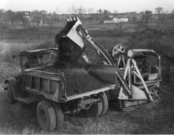
Crawler loader: 1948 Cat D2 with Trackson T2 Traxcavator. The first loaders were cable-operated attachments mounted to tractors. This design originated in the late 1920s and was phased out in 1952.
Crawler loader: 1948 Cat D2 with Trackson T2 Traxcavator. The first loaders were cable-operated attachments mounted to tractors. This design originated in the late 1920s and was phased out in 1952.
Crawler loader: 1957 Cat 977D. The all-hydraulic crawler loader attachment was perfected in 1946, and in 1954 Cat’s No. 6 Shovel was the first machine built from the ground up as a crawler loader.
Crawler loader: 1957 Cat 977D. The all-hydraulic crawler loader attachment was perfected in 1946, and in 1954 Cat’s No. 6 Shovel was the first machine built from the ground up as a crawler loader.
Multi-Terrain Loader: Since the 1980s, loaders and tractors have been made with wide tracks for use in soft or sensitive ground. The wider tracks leave less imprint by supporting the machine’s weight.
Multi-Terrain Loader: Since the 1980s, loaders and tractors have been made with wide tracks for use in soft or sensitive ground. The wider tracks leave less imprint by supporting the machine’s weight.
Overshot loader: For use in confined areas, some loaders from the 1930s through 1960s dumped by hoisting the bucket forward – or back – over the tractor to dump at the other end without turning.
Overshot loader: For use in confined areas, some loaders from the 1930s through 1960s dumped by hoisting the bucket forward – or back – over the tractor to dump at the other end without turning.
Wheel Loader: 1940s Scoopmobile B. Like the Trackson Traxcavator, the first wheel loaders operated by cable. The Scoopmobile was pulled behind a truck and steered from the handle over the seat.
Wheel Loader: 1940s Scoopmobile B. Like the Trackson Traxcavator, the first wheel loaders operated by cable. The Scoopmobile was pulled behind a truck and steered from the handle over the seat.
Industrial Wheel Loader: 1956 Hough HAC. From the 1940s until the skid-steer loader replaced them, these small loaders were used in warehouses, ship’s holds, boxcars and other industry applications.
Industrial Wheel Loader: 1956 Hough HAC. From the 1940s until the skid-steer loader replaced them, these small loaders were used in warehouses, ship’s holds, boxcars and other industry applications.
Industrial Wheel Loader: 1956 Hough HAC. From the 1940s until the skid-steer loader replaced them, these small loaders were used in warehouses, ship’s holds, boxcars and other industry applications.
Industrial Wheel Loader: 1956 Hough HAC. From the 1940s until the skid-steer loader replaced them, these small loaders were used in warehouses, ship’s holds, boxcars and other industry applications.
Skid-steer Loader: 1969 International 3200A. Developed in 1957, the skid-steer turns by stopping motion of one tire or another, rather than by angling the wheels.
Skid-steer Loader: 1969 International 3200A. Developed in 1957, the skid-steer turns by stopping motion of one tire or another, rather than by angling the wheels.
Wheel loader: 1976 Trojan 4000. Most modern wheel loaders steer from an articulation joint behind or ahead of the cab. Developed by Mixermobile Manufacturers in 1955, it became standard in the 1960s.
Wheel loader: 1976 Trojan 4000. Most modern wheel loaders steer from an articulation joint behind or ahead of the cab. Developed by Mixermobile Manufacturers in 1955, it became standard in the 1960s.
Swing loader: 1950s Mandt 78. Some wheel loaders are built with booms that swing left or right for work in confined areas. Such loaders are popular in railroad maintenance.
Swing loader: 1950s Mandt 78. Some wheel loaders are built with booms that swing left or right for work in confined areas. Such loaders are popular in railroad maintenance.
Log loader: Terex 72-31B. Wheel loaders and similar machines can be equipped with a wide variety of attachments. This example has forks for loading and handling logs.
Log loader: Terex 72-31B. Wheel loaders and similar machines can be equipped with a wide variety of attachments. This example has forks for loading and handling logs.
Loader/landscaper: Case 990. Combining a loader and a rear-mounted box scraper or blade results in a handy machine for site grading and light earthwork.
Loader/landscaper: Case 990. Combining a loader and a rear-mounted box scraper or blade results in a handy machine for site grading and light earthwork.
Loader/backhoe: 1967 Case 580. This very common machine combines the features and functions of a wheel loader and a hydraulic backhoe into a single, very versatile and highly mobile machine.
Loader/backhoe: 1967 Case 580. This very common machine combines the features and functions of a wheel loader and a hydraulic backhoe into a single, very versatile and highly mobile machine.
Overshot loader: For use in confined areas, some loaders from the 1930s through 1960s dumped by hoisting the bucket forward – or back – over the tractor to dump at the other end without turning.
8. EIMCO-FINLAY mechanical loader in operation in a drift above 19 level in Bunker Hill and Sullivan Mining and Concentrating Company"s mine at Kellogg, ID

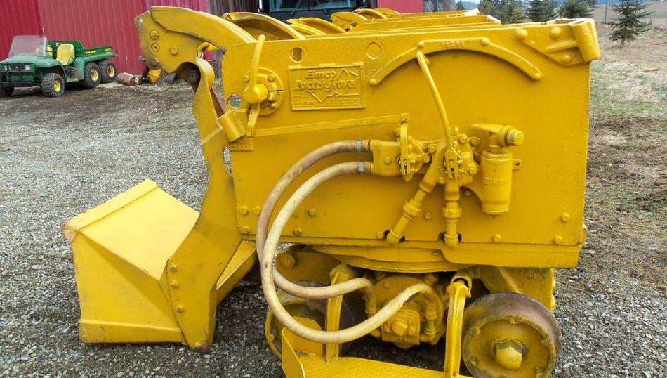
Heres a not so clear pic of a machine Im desperately trying to save. Its rare especially here. Its an old Eimco overshot loader or rocker loader. I dont have the specifics on the model or the year but it was used by Ballew and Roberts contracting later bought out by APAC. I met the owners of this machine several years ago buyin up some old Cat grader scarifier teeth he had for sale and to see his old DW21 scraper. I didnt know this machine was in back of his lot but found it when I was looking for him one day. I talked to my neighbor that had a company back then that worked with them and I was talking about Eimco over loaders and he told me of this one. When I realised it was the same machine he told me about watching it work in his hotmix plant loading hoppers. He told me that the Cat dealer came out with a new 922 trying to sell it to them for hopper loading.
He was out there seting up a deal for mix and the Cat dealer came out trying to getthe old Overloader retired. They set up a deal with Cat to get a loader man and run the 922 against the Eimco The aggregate piles were adjacent to the matching hoppers. When they started the 922 was right on there till the 3rd oad the Eimco was ahead all day.

A MACHINE IS INVENTEDThe manual removal of the rubblehad long been recognized as timeconsuming; back breaking; requiringmany laborers; and costly. Manyattempts to mechanize the laborer’smovements and work were unsuc-cessful until a revolutionary designwas conceived by Edwin Burt Royle.He and John Spence Finlay developeda machine initially called an “OvershotLoader”, that worked within the con-fines of low and narrow tunnels.The artist’s drawing at right showsJohn Spence Finlay and the machinethey produced.
The two men were employees ofAnaconda, a mining company. Both DRAWING BY BUCK O. DONNELL, 1967. It had the following written on it.Worked at the North Lilly Mine in “John Spence Finlay, Superintendent of the North Lilly Mine, Eureka, Utah revolutionized mining with the development of his Overshot Loader. Back inEureka, Utah in the 1920’s and 1931 he built and sold four of these units for $1,600 each.”Early 1930’s.
A nephew of Joe, Barney Rosen-blatt recalls going to Eureka inabout 1931 with the Rosenblattbrothers to see the OvershotLoader developed by Finlayand Royle. CAST BRONZE SHIELD WITH RELIEFS OF THE FOUR ROSENBLATTS
By 1934 the Rosenblatt family had committed itself to invest in developing the machine.Joseph Rosenblatt later recalled, “the 2, 134, 582EIMCO Finlay loader was actually the LOADING MACHINEbrainchild of Burt Royle, although Edwin B. Royle, Salt Lake City, Utah, Assignor toRoyle’s name was not identified with The Eimco Corporation, Salt Lake City, Utah Application May 28, 1937, Serial No. 145,281the loader (except on the patent). 6 Claims (Cl. 214-132)During the early 1930s Royle joinedEIMCO Corporation as a consultantand designer. Royle, a quiet unassum-ing man was considered by some askilled engineer, although he neverreceived any formal training.”
Mr. Rosenblatt also stated, “Developmentof the loader required much engineeringinput. It was not a simple machine. Anumber of patents were required as it 1. In a loading machine, the combination withwas constructed. Also, Burt Royle and a support, a horizontally oscillatableJohn Finlay had fashioned their first superstructure, a vertically swinging shovel mounted on the superstructure, andworking machine from discarded Model means for swinging the shovel, of aT Ford (automobile) parts; crude air central cam member mounted on the support,motors stripped from a worn out a rotary drum mounted transversely of thecompressor; the sprockets, chains, superstructure having a cam-edge, and power transmitting means between theand drive wheels from a motorcycle, shovel swinging means and said rotaryand small wheels from a mine haulage drum.car. Most important, it worked.” SOURCE: OFFICIAL GAZETTE U.S. PATENT OFFICE. SEP-OCT 1938.
The EIMCO Rocker Shovel Loader, Model 12Bwhen first introduced about 1938 appearedmuch the same as shown in a photograph onthe front page of an EIMCO Rocker ShovelLoader sales bulletin as seen at right.
The bucket, rocker arms, controls and oper-ating platform show clearly in the photograph. HISTORICAL SIGNIFICANCEThe EIMCO Rocker Shovel Loader provided the means for a significant boost in mineworkerproductivity. Its acceptance was instant. Its introduction to the market place was just prior to thestart of World War II, and it was in demand to help increase the production of war-related metals.Many mining companies purchased ten or more at a time. Russia ordered approximately eightymachines. In addition to yeoman duty in the mines, the loader was used in non-metal hard rockexcavations for bomb shelters and tunnels on Malta and Gibraltar, which significantly fortifiedAllied installations in the Mediterranean Sea during the war. In the 1950s the government of Francehonored Joseph Rosenblatt with a merit award for the role of the Eimco Rocker Shovel Loader in theadvancement of underground mining in that country.
The model 12B design with a bucket capacity of four to six cubic feet allowed loading of twenty tothirty cubic feet of rubble per minute, but it was evident that greater capacities would be required.The design concept was extended to larger bucket sizes. In all, EIMCO would develop five basicsizes of loader accommodating buckets of from four to thirty-five cubic feet capacity. Itsapplication expanded from underground mining to non-mining tunneling and other excavationrequirements. 21 Loader 128 Loader Bucket 7.5 – 10 Cu. ft. Bucket 4.5 – 6 cu. ft. (0.25-0.34 cu. m.) (0.13-0.17 cu. m.) Weight 7,200 Ibs. Weight 4,200 Ibs. (3,260 kg.) (1,905 kg.)
Park City Municipal Corporation decided to place this EIMCO Rocker Shovel Loader, Model 12B withits commemorative ASME plaque in Miner’s Plaza. Miner’s Plaza is a small park in historic old ParkCity that serves as a reminder of the major role the mines played in Park City history. There areapproximately 1200 miles (1931.2 kilometers) of mine tunnels under Park City. Most of thattunneling was mucked with a model 12B loader obtained by the mine in the 1940’s. This Loader isthe same model as the machine used for the tunneling.
The success of the Rocker Shovel Loader was a boost to Salt Lake City where in 1957 there werenineteen hundred employees at the EIMCO facilities. Manufacturing rights were licensed tocompanies in Great Britain, India, South Africa, and Japan. Sales and service offices outside theUnited States were located in Australia, Canada, Chile, France, Mexico, Spain and Zambia. By 1969,twenty-nine thousand Rocker Shovel Loaders had been sold.
EIMCO had expanded into other product lines, and the Loader Division eventually became EIMCOMining Machinery International. In approximately 1980, EIMCO Mining Machinery International wassold and it is now a part of The Sandvik Group (Sandvik AB) headquartered in Sandviken, Sweden,under the name of Tamrock Loaders. A large number of EIMCO Rocker Shovel Loaders are known tobe operating in South African gold mines and elsewhere in the world, and parts are occasionallyordered for them. Used Model 12B machines occasionally are advertised on the Internet.
Front view showing of bucket and rocker arms Drawing with major components identified. EIMCO Rocker Shovel Loader Model 12B
The above photograph and descriptive drawing will be used to describe function and operation ofthe EIMCO Rocker Shovel Loader. The photograph has been sized to approximately the same scaleas the drawing. In both the photograph and the drawing the bucket of the loader is shown in the“digging” position and resting on the rails. The bucket is also shown in the “discharge position” onthe drawing.
The model 12B machine weighs 4200 pounds. (1905 kg.) The required air pressure is 60-125pounds per square inch (413-861 kPa). Air consumption is 250 cubic feet (7.1 cu. m.) per minute.When the bucket is loaded with rubble, the operator actuates the bucket drive motor, whichexerts force on the rocker pull chain, which is attached near the outer end of the rocker arms, andthe rocker arms commence to roll toward the rear of the machine. The bucket is attached to therocker arms in a manner that provides maximum initial lift force on the bucket. As the arms roll,the geometry causes the bucket, with its contents, to travel upward and rearward. During thebucket travel, its vertical velocity decreases, and its horizontal velocity increases until the rockerarms strike shock absorbing stops on the frame. When the bucket stops, its contents continueto travel into a mine car attached to the Loader. The magnitude of the forces required to lift andthrow the contents is substantial, and the machine was designed to withstand them repeatedly.Cables are attached to the rocker arms and to the frames to prevent the rocker arms fromcoming out of the machine.
One set of the cables may be seen in the photograph below that shows a loader in operation in atypical small mine tunnel in which the machine was designed to operate. This photograph is seen from the front with the bucket in the discharge position.
HISTORIC MECHANICAL ENGINEERING LANDMARK EIMCO ROCKER SHOVEL LOADER, MODEL 12B PATENTED OCTOBER 25TH 1938
THIS MACHINE REPRESENTS THE FIRST SUCCESSFUL DEVICE TO REPLACE HUMAN LABOR IN REMOVING THE RUBBLE RESULTING FROM BLASTING IN UNDERGROUND HARD-ROCK MINES. IT IS OPERATED ENTIRELY BY COMPRESSED AIR. AS THE LOADER MOVED FORWARD ITS BUCKET DUG INTO THE RUBBLE. WHEN FULL. THE BUCKET LIFTED, AND WITH A SNAP, THREW THE RUBBLE REARWARD INTO A MINE CAR FOR REMOVAL.
THE LOADER, DESIGNED BY EDWIN BURT ROYLE AND JOHN SPENCE FINLAY, WAS DEVELOPED, MANUFACTURED, AND SOLD INTERNATIONALLY BY EIMCO ASME International CORPORATION, SALT LAKE CITY.
UNITED PARK CITY MINES COMPANY: Hank Rothwell, Chief Executive Officer, for the donation of theEIMCO Rocker Shovel Loader to Park City Municipal Corporation, and Richard Martinez, Sr. anemployee of United Park City Mines Company, who, years ago, was an operator of the Rocker ShovelLoader in the mines for his efforts in making possible the ASME designation and display of thatmachine.PARK CITY MUNICIPAL CORPORATION: Mayor Bradley Olch; Council members Fred Jones, Peg Bodell,Candace Erickson, Roger Harlan, and Shauna Kerr; as well as Denise Payne for coordination of thedesignation ceremony in conjunction with the annual Park City’s Miner’s Day activities.PARK CITY ROTARY CLUB for its efforts in furthering the success of the designation ceremony aspart of the Park City Minor’s Day activities.Wayne L. Dowdey, formerly Vice President of Sales for EIMCO and President of the AmericanInstitute Of Mining Engineers, 1978.Donald N. Rosenblatt and Barney Rosenblatt for product and family information.Lars Olavson, former EIMCO employee for assistance in obtaining historic information.Berne A. Schepman, President of EIMCO Corporation succeeding Joseph Rosenblatt, forinformation on operating Rocker Shovel Loaders at present.Randy Fridulin of Tamrock Loaders, Burlington, Ontario, Canada, for historic product information.Jewel M. Weston, formerly secretary for EIMCO Legal Services.Park City Historical Society, Sandra Morrison.Utah Section of ASME for sponsoring the Landmark designation.Donald L. King, brochure preparation.ASME International


 8613371530291