
overshot tool free sample

Drilling tool fishing is probably every driller’s least favorite activity. But it happens. There are a huge number of tools available to fish almost anything out of the hole. For drill pipe and collars, there are overshots and spears — in many sizes for almost any job. But, when it comes to loose junk on the bottom of the hole, things get a little more interesting. It might be a loose bit, a wrench, a sledge hammer or tong dies. Anything that can fit in the hole will sooner or later end up on the bottom. I reckon it’s human nature, or Murphy’s law, but it happens.
Most commercial fishing tool companies have pretty sophisticated tools, such as reverse circulation junk baskets, and all kinds of well-engineered tools to do the job. But, sometimes, they are not quite what a customer needs. If the fish is large in relation to the hole size, such as a bit, a reverse basket will not pick it up because of the wall thickness. Something else is needed. Or, if the hole is just not worth the expense of using a commercial fishing company, a driller may opt to build his own fishing tool for the job.
This brings me to a tool that is often overlooked, but has been around forever and recovered a lot of junk in the hole: the poor-boy basket. Most fishing companies don’t push them because they are not fancy high-dollar tools that make great testimonials, but they work and can be built by the driller on location.
The layout and design of the fingers is very important to the operation of the tool and successful recovery of the fish. I have built these for years and pretty well have it down, so I thought I’d share with you how to lay out the leaves on a poor-boy basket for your best chance of recovery.
Once you’ve built your basket, here is the running procedure:Go in the hole at moderate speed, watching for ledges or doglegs. The basket is a delicate tool, and you need it intact when you get to the bottom.

And I know about this "Honey I dropped the Pump" problem too, and haven"t added a full article on retrieving stuff from water wells at InspectAPedia because of lack of photos of the array of in-well-stuff grabbing tools, and also because I don"t think most homeowners will have much luck retrieving stuff that has fallen into their well on their own.
Magnets or junk magnets, are sometimes used to retrieve smaller metal objects that have fallen into a well; it"s doubtful that a magnet could pull a steel well pipe however. In the oil and gas industry junk magnets are run into a well ahead of a diamond drilling tool in order to remove metal junk that can damage the drilling bit.
Overshoots or Overshots are fishing devices that fit over the exterior of the well pipe and then grab onto the well pipe exterior to enable lifting the pipe.
Logan Oil Tools calls these "external catch" devices. [12] The overshot may be a metal mesh device, or a spiral device, one or more round or oval loops, or similar devices that grab on to the pipe exterior. The overshot was invented by Bowen in 1935.
Logan Oil Tools calls devices of this sort "internal catch" devices.[12] Releasing spears include design features that can when appropriate release the "caught" pipe or component. Spearing tools are used to retrieve piping from a well when it cannot be grasped with an external catch tool.
See WELL FISH TOOL & CAMERA SOURCES at the end of this article for manufacturers of well retrieval tools, well pipe retrievers, well pump retrievers, specialty well repair tools, and for patented designs that suggest home made well pipe retrieval tools.
Jars or bumper tools are designed to impact stuck pipes, spears or other components stuck in a well by hydraulically jarring the stuck component upwards or downwards.
Box Tap / Die Collar, used to retrieve tubular fish tools that can"t be rotated. This is a special type of overshoot used to connect to the top of tubing or piing. See Overshoots below. Produced by Schlaumberger and others.
Casing Swage is a tapered tool used to restore dented or collapsed well casings to approximate its original shape. Note that these tools will not repair a casing that has been broken or corroded through. Well sleeves or casing section replacement is needed in those cases. Speaking strictly this is a casing repair tool not a well retrieval / fishing tool.
I"m doubtful this tool is able to grab a round well pipe (the maximum length is about six feet and the end looks like suction cups) but the company may have tool ends that can be adapted for that purpose.
Pipes in oil and gas drilling become stuck in wells differently from what happens in a drilled water-well or borehole well, but some of the tools developed for the oil and gas industry may also benefit the water well drilling and well retrival tool industry.
The traditional freepoint tool is an electromechanical tool designed to measure the amount of torque or stretch of a given length of tubing, drill pipe, or casing. The traditional freepoint tool uses either bow springs or magnets to anchor itself inside the pipe.
After obtaining an estimate of the free point by using the pipe stretch estimate technique, the traditional freepoint tool is run in the hole to 1000 feet above the estimated stuck point. The tool is anchored in place. Stretch and or torque is then applied to the pipe.
The tool is then run roughly 500 feet past the estimated stuck point. Stretch and torque are applied, and readings are taken. If the tool indicates that the pipe is stuck at that point the tool is pulled uphole and readings are taken again.
The Halliburton Freepoint Tool is based around the magnetorestrictive property of steel. This principle states that when torque or stretch is applied to free pipe, the magnetization will change. Stuck pipe will have no change in magnetization. There is a magnet on the bottom of the tool that creates a small magnetic field.
There are four co-planar orthogonal multi-axis high sensitivity magnetometers located above the magnet. The magnetometers measure the change in the magnetization of the pipe. The pipe is set at neutral weight, then the tool is run downhole logging the entire pipe string. Once it is at the bottom of the string, torque or stretch is applied to the pipe.
The tool is then pulled uphole logging the entire string. The tool will detect differences in the magnetization of the pipe, thereby indicating free and stuck sections of pipe. - Wikipedia, retrieved 2016/05/31, original source: https://en.wikipedia.org/wiki/Pipe_recovery_operations
Pull slowly and smoothly and as soon as you can mechanically grab the end of the lost pipe as it emerges from the well, do so. The pipe tongs shown below, provided by Hole Products (cited below) are used to grip pipe for hoisting; this tool will automatically release the pipe when tension is released on the lift line.
Hydraulic Fishing Jars are tools lowered into a well that grasp onto the stuck pipe, fish, or component to permit freeing a stuck component by jarring it upwards or in some applications downwards or in either direction. (Schlumberger) Fishing jars are also referred to as fishing accelerators.
Magnets for use in a well bore: Hole Products and other well service companies produce powerful magnets that can be lowered into a well to retrieve tools or metal pieces of irregular shape that have fallen into a well and that can"t be grabbed by other tools shown here.
Shown below, a well magnet fishing tool set provided by Hole Products Company whose contact information is given below in this article. Depending on the magnet size these devices can lift 100 to 400 pounds. The largest magnet shown below is 5 1/2" in diameter so may fit inside a 6" well casing.
Overshot mesh well pipe or item retrievers for fishing stuff out of a well: the most effective tools we know about for pulling lost well pipes out of a drilled well are various versions of overshots. Overshots, an "overshoot" type tool, are a bit easier to get over the outside of a well pipe than spear type tools are to get into the well pipe, unless the upper end of the pipe is near the top of the well.
Some supplies use the term "recovery bell" for overshots. The overshot is a cylindrical or conical shaped (bell shaped) device lowered over the upper end of a pipe to be retrieved from a well. Some companies (Schlumberger) produce a releasing overshot or overshots used for jarring or stuck material backoff operations.
The overshot is lowered over the end of the pipe in the well. If there is enough friction around the object the braided sleeve will contract and grab the object when the line is pulled up - like that braided rush "chinese finger trap" trick we played with as kids.
The overshot is attached to the end of a drilling rod or in the water well industry to the end of a section of well piping that is lowerd into the bore hole.
Some overshots include hardened self-cutting threads that will grab onto the upper end of a well pipe that has been dropped into the well borehole, thus allowing the pipe to be retrieved.
Pin Tap / Screw-In Sub taps are used to retrieve a tubular fishing tool or pipe from a well when it is cannot be rotated. Basically this is similar to a "screw extractor" that is reverse-threaded to be turned into a seized bolt, screw, or in this case pipe or fishing tubular tool that cannot be turned or rotated in its normal direction. Produced by Schlumberger and perhaps others. Also see Taper Tap.
PVC Well Casing Elevators: a special clamp-on elevator tool is required to lift a PVC casing or casing liner without breaking it. The tool shown below is provided by Hole Products whose contact information is given below in this article.
Releasing spear well retrieval tools: a releasing spear is a well pipe or tubing retrieval tool that includes an internal catch that retrieves pipes or tubing from a well bore. The releasing spear is lowered into the well where it "spears" the interior of the pipe to be retrieved. Bowen® Itco is a producer of releasing spears.
Taper Taps are produced by Produced by Schlumberger (shown above), Hole Products, and perhaps others. Hole Products also supply sonic taper taps sued to retrieve lost sonic tooling. Contact information for these companies is given below. Similar tools include packer milling and retrieving tools designed to drill through plugs in a well bore.
Washover shoes, (shown above) strictly speaking are not retrieval tools but rather devices that are used to free pipe that has been stuck or lodged in a well bore due to fallen debris or other obstructions.
Watch out: when buying or fabricating a tool to pull a dropped well pipe or something else out of a well, be careful not to drop your new tool into the well alongside what"s already in there. Test your device above ground first and also be sure it"s strong enough and long enough to do the job.
Note that the primary producers of well retrieval and fishing tools are companies serving oil and gas drilling industry companies. However many of these also serve the water well drilling industry too.
Check with your local well driller as those folks will have more experience, retrieval tools, and probably safer procedures than a normal property owner. The savings in time and money by hiring a professional may be more than you first guess.
Bowen Itco, owned by NOV since 2000, produces well fishing tools, devices, equipment including the Bowen™ Itco-Type Releasing Spear . The company"s website provides no street address but includes a contact page, Website: http://www.nov.com/bowen/default.aspx
Belle Plaine, KS 67013 USA, Dapalco produces the Fetch well pipe retrieving tool. Website: http://www.dapalco.net/ or www.thefetch.net Tel: 866-397-7347 Email: aprinter@sktc.net
This pipe fishing tool uses a jaw with two tips and a center slot. One leg of the jaw slips into the upper end of a cut-off pipe inside the well and jaw teeth grip the pipe wall to permit lifting it. Lifting capacity: 250 lbs. U.S. Patent No. 7,665,785
A catch tool for retrieval of a well column pipe having a pipe wall, the catch tool incorporating a fork having a pair of spaced tines; and a pair of clamping pivot arms connected operatively to the fork, the clamping arms being adapted for, upon the receipt by the tines of the pipe wall, grasping the pipe wall;
Gotco Corp., 11410 Spring Cypress Rd., Tomball TX 77377 USA, Tel: 1-800-OVERSHOT, produces the Gotco Grapple Releasing Spear. Except from the company"s website:
Schlumberger Fishing Tools and Services, 3750 Briarpark Dr., WG-3 Level-2, Houston TX 77042, produces a wide range of oil and gas drilling tools and equipment and opeates world-wide. North American Contact: Schlumberger Technology Corporation
Stuckey"s Specialty Tools, Fishing Tools & Specialized Equipment, 2511 Lauder Road, Houston, Texas 77039, E-Mail: stusptl@yahoo.com Website: http://www.stuckeyspecialtytools.com/ producing an Itco type releasing spear
EvCam provides a variety of downwell and well bore inspection cameras that can help identify well obstructions and dropped objects to combine with a wellbore fish tool to retrieve dropped materials from a well.
I don"t have comment to you because is my first time to see some of fishing tools and the quality are good but my humble request is how can a pump machine like me who can"t afford to get or buy can manage to have it.
Century Foundation Company that posted before we are one in the same. If interested in seeing this tool it is for sale call number or email centuryfoundationcompany@gmail.com
I have a tool I made in my machine shop that will go get ANYTHING in a water well or oil well no difference not like the stuff shown here. Drop a pipe wrench in the hole I will have it back in 5 minuets guarantee. 93sixsevenone 8 one three two 5
You are welcome to post a photo of your tool here and if you use the page top CONTACT link we can look at your info for addition to sources of well pipe grabbing tools in this article series.
. It will go any distance bring back anything. It will retrieve and bring it back in about 10 minutes. There is only one of theses tools in the world and I made it. I can make one for any size Id pipe. If you need one contact me. Century Foundation Company magnolia Texas is on net.
When you lower a well cam you can see if there is a rope or pipe that"s likely to be able to be grabbed by one of the retrieval tools we illustrate; you basically have to match the tool to the space available, to what"s in the well, and to the position of the fallen materials.
Aside from the dropped well pump or pipe tools shown in our article above, I"ve read that some well pump retrieval projects had success by trying a piton or crevice clamp (mountaineering equipment) or even a simple small grappling hook that snagged a dropped well rope.
finally got to the bottom and the water pump wasn"t at the end of the pipe.... the wires had somehow been severed and I"m not sure how or why it happened but I need advise on tools that I could use or make to use to grab onto the piece of pipe and pump that is still sitting at the bottom of our deep well.
I lost a section of pipe and a tool in my well trying to pull out what was dropped in by a previous well company. The pull line broke. Can I just leave it there?
It"s probably possible to retrieve the ring, though it"ll be some trouble. Check with your well driller to see what small-object retrieval tools they have on hand. There are two approaches:
Fair question, Tina but prices are all over the place depending on the particular pipe grabber tool and its appilcation, from $10. to $1000 or more. The "Fetch" pipe spear described in the article above retails for about $500. U.S.
Other readers: Mr. Myers reference to a "slip tooth" probably refers to an anchoring mechanism for a well tool that allows for movement in directions other than straight vertical.
The most expert deep well drillers in the world come from the oil and gas fields. One of their approaches for tool jams such as the one you describe, if a grabbing tool can"t remove the fallen object, is to drill through it.
I got an old shallow well and my inner pipe is a inch and a quarter inside the case and the top three threads broke off when was trying to pull it out what kind of tool do I need to get that inner pipe out and where can I find it
While I like a pipe spear for the situation you describe, most of the well pipe grabbers described in the article above or a home-made version of one of them ought to work; to save time and trouble give your local well drilling contarctor a call as they probably have several of these tools at hand plus the lift or winch needed.
WELL RETRIEVAL TOOLS at InspectApedia.com - online encyclopedia of building & environmental inspection, testing, diagnosis, repair, & problem prevention advice.
[11] "Overshot Definition", OilGasGlossary.com. Oil & Gas Field Technical Terms Glossary, Web Search 04/21/2012, original source: http://oilgasglossary.com/overshot.html
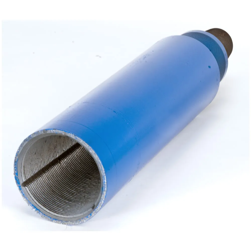
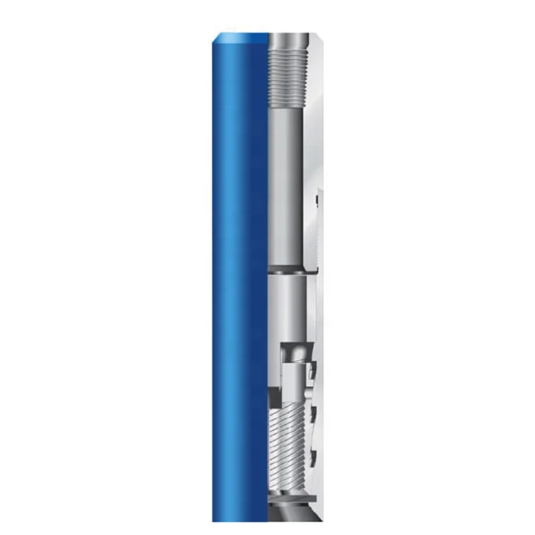
The present invention relates to an overshot tool having means for engaging and disengaging a latch in a core barrel head assembly used in core drilling operations and in particular although not exclusively to an overshot tool having an automated latching control mechanism to allow automated coupling and retrieval of the head assembly from within a bore hole. BACKGROUND ART
With either locating an inner tube assembly within a drill string or retrieving an inner tube assembly, when the inner tube is full, it is most often the case that an overshot tool is used to either lower the inner tube assembly into place, be used to pump the inner tube assembly into place or be lowered by itself to retrieve the inner tube assembly. In the case of a dry hole, the overshot tool will hold the inner tube assembly and their combined weight will allow the inner tube assembly to be lowered into position. In the case of a wet hole, or where the hole is partially wet or where the hole is horizontal, inclined upwardly or upwardly vertical, then the overshot tool has a sealing section which is fluid tight and enables fluid pressure to push the overshot tool and the attached inner tube assembly along the drill tubing.
The overshot tool, when used to retrieve an inner tube assembly when the inner tube assembly is full, can either fall under gravity to latch with the core barrel assembly or again be pumped into place to latch with the core barrel assembly.
The overshot tool needs to cooperate with this latch so that the inner tube assembly can be held with respect to the overshot tool when it is being placed into position within the drill string and core barrel or alternatively must cooperate with the latch when the overshot tool is being used to retrieve the inner tube assembly.
In the case of retrieval, the overshot tool needs to engage the latch so that it releases the inner core assembly from the core barrel while at the same time the latch also needs to engage the overshot tool so that the overshot tool is held by the core barrel latch which allows for withdrawal of the inner tube assembly from the drill tube.
Various means exist for performing all of the above functions. However, it is the case that there are a number of different pieces of equipment that are used depending on the type of hole being drilled. The hole may be wet or dry and it may be vertically down or vertically up or any inclination in between. This means that the set of equipment, being the inner tube assembly and overshot tools differ in their configuration and operation depending on the type of hole being drilled.
It is an objective of the present invention to provide an overshot tool configured to cooperate with a latch mechanism of a head assembly via an automatic coupling/decoupling engagement such that the tool may be coupled to the head assembly and both components retrieved from the borehole quickly, conveniently and reliably. It is a further specific objective to provide an arrangement that provides both automated and manual decoupling of the tool from the head assembly to allow detachment by personnel at the surface and decoupling down the hole when the overshot tool is used to deliver the head assembly into the final latched position at the cutting end of the core barrel apparatus.
It is a further specific objective to provide an overshot tool that is sensitive to the method of delivery down the borehole so as to provide a feedback signal to an operator that the tool has reached its desired destination at the head assembly. It is a further specific objective to provide an overshot tool that is resistant to decoupling from the head assembly when used to deliver the head assembly into position should the assembly encounter obstructions during delivery.
The automated coupling and decoupling function of the present overshot tool is provided by primary and secondary engaging portions where at least one of the engaging portions is controlled by a latch control that is responsive to the environment in which the tool is placed and additionally the forces acting on the tool. Accordingly, the latch control is configured to control an axial and optionally a rotational movement of the primary and secondary engaging portions. The coupling and decoupling is achieved specifically via engagement by the primary engaging portion (to provide coupling) and the secondary engaging portion (to provide decoupling). The specific activation of the secondary engaging portion is controlled by the latch control and is responsive to forces acting on the tool at the cutting end of the borehole where the head assembly is maintained or released at its latched position against the inner surface of the core barrel. Additionally, the specific objectives are achieved by providing a latch control that is conveniently implemented as a pin and slot arrangement acted on by a bias member that is configured to provide from either an axially forward or rearward end.
According to a first aspect of the present invention there is provided an overshot tool for releasable connection to a head assembly of a core barrel drilling apparatus, the tool comprising: a primary engaging portion to engage a latch of a head assembly to provide an axial couple between the tool and the head assembly; a secondary engaging portion to temporarily engage the latch in addition to the engagement of the latch by the primary engaging portion; a retainer acting between the primary engaging portion and the secondary engaging portion; a housing having a region for engagement by the retainer, the primary engaging portion and the secondary engaging portion axially movable relative to the housing, the retainer configured i) to engage a first part of the region to releasably couple the primary and secondary engaging portions for combined axial movement and ii) to engage a second part of the region to allow at least partial independent axial movement of the secondary engaging portion relative to the primary engaging portion; a bias member acting between the housing and the secondary engaging portion to bias the secondary engaging portion axially relative to the primary engaging portion; wherein by adjustment of a position of the retainer between the first part and the second part of the housing the tool is adjustable between a first mode to allow axial coupling between the tool and the head assembly and a second mode to provide a decoupling of the tool from the head assembly.
Preferably, the primary engaging portion comprises an elongate shaft and the secondary engaging portion comprises a sleeve positioned around the shaft, the sleeve configured to slide axially over the shaft. The elongate shaft comprises an axially forwardmost end that represents an axially forwardmost part of the tool and is configured specifically to engage the latch of the head assembly.
Preferably, the housing comprises a slot in which the first and second parts of the housing comprise regions of the slot and the retainer is capable of movement within the slot between the first and second parts. Preferably, the bias member is configured to bias the secondary engaging portion rotatably relative to the primary engaging portion. Preferably, the bias member is a coil spring extending between the housing and the secondary engaging portion. Such an arrangement is advantageous to provide a reliable and robust configuration for the latch control mechanism that provides the automated or semi-automated latching of the secondary engaging portion and hence a coupling and decoupling action of the tool.
Preferably, the tool further comprises a cover member to accommodate the primary and the secondary engaging portions and the housing wherein the primary and secondary engaging portions and the housing are capable of sliding axially within the cover member. The cover member acts to protect the inner components of the tool and to allow the various components to slide axially and rotate circumferentially around the axis in use.
Optionally, the tool further comprises a temporary rotational lock having at least two locking positions to temporarily lock the housing at the cover member at two rotational positions. The rotational lock is configured to provide quantised default positions of the secondary engaging portion relative to the housing and the primary engaging portion. Accordingly, a degree of force is required to adjust the releasable lock between the two positions so as to change the state of the tool to be configured for latching or unlatching of the head assembly. Such force may be provided by the pressure of a supply fluid or the weight of a free fall delivery assembly acting on the overshot tool.
Preferably, the retainer is fixed to and projects radially from the shaft and through the slot in the housing wherein the bias member is configured to force rotational and axial movement of the retainer within the slot. Accordingly, the retainer forms a radially extending region of the shaft such that rotational and axial adjustment of the retainer provides a corresponding movement of the shaft relative to the other components of the tool. The relative position of the shaft is therefore determined by the relative position of the retainer within the various slots and channels of the present overshot tool.
Optionally, an engaging end of the primary engaging portion comprises a bayonet configuration at a leading end of the tool being engagable with the latch; and an engaging end of the secondary engaging portion comprises a bell portion to engage the bayonet configuration in touching or near touching contact and release the bayonet configuration from engagement with the latch. Such an arrangement is advantageous to engage a particular configuration of latch at the head assembly that may comprise resiliently biases latching arms having engaging ends movable radially inward and outward.
Preferably, the housing of the tool comprises a coupling portion at a trailing end of the tool to mate with a valve housing or a free fall overshot attachment, the coupling portion capable of sliding axially within the housing and independently of an axial movement of the primary engaging portion. The present tool therefore is configured to mate with an overshot attachment or a valve housing to allow the tool to be both delivered and extracted from the borehole when coupled or decoupled from the head assembly. The latch control of the tool is configured to be sensitive to the coupling state of the valve housing or overshot attachment at the tool to both provide a feedback signal to an operator at surface level and to change the coupling state of the tool to either couple or decouple at the head assembly.
According to a second aspect of the present invention there is provided a method of core drilling using a tool forming part of a core barrel drilling apparatus, the method comprising: transporting an overshot tool in an axially forward direction through a core barrel apparatus; engaging a latch of a head assembly via a primary engaging portion of the tool to decouple the head assembly from fixed axial position at the core barrel apparatus and to axially couple the tool to the head assembly; transporting the coupled tool and the head assembly in an axially rearward direction through the core barrel apparatus to retrieve the head assembly, wherein the tool comprises: a primary engaging portion to engage the latch of the head assembly to provide the axial couple between the tool and the head assembly; a second engaging portion to temporarily engage the latch in addition to the engagement of the latch by the primary engaging portion; a retainer acting between the primary engaging portion and the secondary engaging portion; a housing having a region for engagement by the retainer, the primary engaging portion and the secondary engaging portion axially movable relative to the housing and the retainer configured to engage a first part of the region to releasably couple the primary and secondary engaging portions for combined axial movement and the retainer configured to engage a second part of the region to allow at least partial independent axial movement of the secondary engaging portion relative to the primary engaging portion; a bias member acting between the housing and the secondary engaging portion to bias the secondary engaging portion axially relative to the primary engaging portion; wherein by adjustment of a position of the retainer between the first part and the second part of the housing the tool is adjustable between a first mode to allow axial coupling between the tool and the head assembly and a second mode to provide a decoupling of the tool from the head assembly.
Optionally, the method may further comprise a release of the axial couple between the tool and the head assembly by moving axially the secondary engaging portion to contact the latch and releasing engagement between the primary engaging portion and the latch.
In one embodiment, the overshot tool has a first means for engaging a latch in a head assembly, the latch locking to the first means when engaged, and latch control means associated with the first means which is movable with respect of the first means wherein, in a first position, the latch control means allows the first means to engage the latch, and in a second position, the latch control means opens the latch to release the first means from the latch.
The first means on the overshot tool may comprise a number of different arrangements for connecting to the latch in the head assembly. Preferably the first means may comprise a spike which locates into and engages with the latch in the head assembly. Other arrangements may be suited to the first means and will depend on the type of latch used in the head assembly. For the sake of clarity, the first means will be described in the remainder of the specification as comprising a spike, however it will be realised that the invention is not to be restricted to this particular feature.
The spike preferably has a tip that is shaped to that it will pass through the centre of the latch assembly so that the latch moves to allow the tip portion to pass through and, once the tip portion has passed the ends of the latch, the latch arms then closed behind the tip portion to thereby retainably engage the spike. In this position, with the latch engaged on the spike, the upper ends of the latch arms are withdrawn inwardly towards the head assembly so that they will disengage from the locking coupling and allow the inner tube assembly to move within the drill tube. This therefore allows the overshot tool to either retrieve an inner tube assembly by unlocking the latch from the locking coupling or lower the inner tube assembly into the drill tube by having the upper ends of the latch arms withdrawn from their latching position.
In all cases, the latch control means operates to disengage the latch from the spike to thereby allow separation of the overshot tool from the inner tube assembly. In the case of when the overshot tool is delivering the inner tube assembly to the end of the drill string, this must be achieved remotely and at the surface, the manual disengagement must allow for easy and safe disengagement.
Preferably, the movement of the latch control means can be initiated remotely from the surface. When the overshot tool is returned to the surface it can be operated manually in a manner that is quick and convenient for an operator and does not involve any potential for injury to be caused or for any loss of or damage to the inner tube assembly.
FIGS. 6aand 6bshow cross-section views of an overshot tool and valve housing and show the overshot tool releasing from the latches of an inner tube assembly,
FIGS. 10aand 10bshow cross-section views of an overshot tool and valve housing assembly engaged with an inner tube assembly to locate the inner tube assembly in a drill string,
FIGS. 12aand 12bshow the overshot tool connected to an inner tube assembly in preparation for delivery of the inner tube assembly to the core barrel of a drill string,
FIG. 13cshows a part view of the release mechanism part way through the operation of the release mechanism, and FIGS. 13aand 13bshow the overshot tool as it relates to the position of the release member shown in FIG. 13c, and
FIG. 14cshows the release mechanism in the position where the overshot tool is released from the core barrel head and FIGS. 14aand 14bshow the overshot tool as it relates to the position of the release member shown in FIG. 14c. DETAILED DESCRIPTION OF PREFERRED EMBODIMENT OF THE INVENTION
FIG. 1 shows an overshot assembly which is an assembly of an overshot tool 10 and valve housing 11. The overshot tool 10 is used to retrieve an inner tube assembly. It can also be used to deliver an inner tube assembly to the end of a drill string. The valve housing 11 can be used to pump the overshot tool 10 through a drill string. This will normally be to retrieve the inner tube assembly. The valve housing 11 is provided with seals 12 which provide flexible fluid seals between the valve housing 11 and the inner wall of the drill tube. An indicator valve 13 is provided within the valve housing 11 to provide an indication to the driller when movement of the valve housing 11 ceases. The indicator valve 13 is shown in FIG. 1 in its open position and comprises a ball 14 and fluid flow ports 15. In its open position, the indicator valve allows fluid that is pumped in behind the valve housing 11 to flow through opening 16 and the fluid flow ports 15. In its closed position and in order to pump the valve housing 11 along drill tubing, the ball 14 is set behind valve seat 17 which prevents fluid flow through the valve housing 11 and therefore enables fluid pressure to move the valve housing 11 along the drill tube (as shown in FIG. 3a).
Upon the valve housing 11 becoming stationary as would be the case when the overshot tool 10 engages an inner tube assembly, an increase in fluid pressure will cause the ball 14 to move through the valve seat 17 from the position of FIG. 3ato its position of FIG. 1 so that the fluid ports 15 are now open and allow fluid to freely flow forward of the valve housing 11 and around the overshot tool 10. This change in pressure provides an indication at the surface to the drill operator that the overshot tool 10 has landed. The valve housing 11 has a wire rope connector 18 to which a retrieval wire rope is secured. This enables the overshot tool 10 and valve housing 11 combination to withdraw an inner tube assembly from the drill hole. The valve housing 11 is secured to the overshot tool 10 either threadably or by a pin or both. The overshot tool 10 comprises a spike 20 and a latch control means 21. The latch control means 21 has an axial bore through which a portion of the shaft of the spike 20 locates. The spike 20 and latch control means 21 are located within a housing 22 and the housing 22 is in turn located within a cover member 23.
Figure groups 4 to 7 show the engagement of the overshot tool 10 with an inner tube assembly. The Figures show a head assembly 47 and do not include the inner tube in which the sample is collected. The inner tube is threadably connected to an end of the head assembly 47. The head assembly 47 combined with the inner tube is referred to as the inner tube assembly.
FIGS. 4aand 4bshow the overshot tool 10 that has been pumped into a hole and has just engaged with the latches 48 of the head assembly. The latches 48 comprise a pair of arms 49 that are pivotally connected to the head assembly 47 via pivots 50. The inner ends 51 of the latch arms 49 locate behind the ledge 37 on the spike 20. An elastomeric o-ring 52 locates around the inner ends 51 and bias the inner ends 51 so that they engage against the head portion 44 of the spike 20. This holds the inner ends against the ledge 37 to thereby hold the latch 48 in a closed position with respect to the spike 20. The arms 49 have upper ends 53 which abut with the locking coupling of a drill string (not drawn) to hold the head assembly 47, in its drilling position where it is positioned to receive core sample as drilling progresses. In order for the upper ends 53 of the latch 48 to engage with locking coupling in the core barrel, the upper ends 53 need to project radially outward to a greater extent than what is shown in FIG. 4b. The diameter of the head portion 44 of the spike 20 is sized so that the inner end 51 are pushed outwardly against the O ring 52 to thereby retract the upper ends 53 to the position shown in FIG. 4b. This retracted position of the upper ends 53 provides clearance both with respect to the locking coupling and the inner wall of the drill tubing.
The example shown in FIGS. 4a, 4b, 4c, 5a, 5b, 5cand 5dare where the overshot tool 10 is required to be pumped into position which may be the case in respect of a wet hole where a column of water is maintained within the drill tube. It may also be the case in respect of a horizontal or upwardly inclined hole. Generally, it is required in a hole that is not sufficiently vertical (in the downward direction) to allow free fall of the inner tube assembly and associated overshot assembly.
FIG. 4cillustrates the setting of the cover member 23 for retrieval. FIGS. 4aand 4bshow the overshot tool 10 just as it connects to the head assembly 47 that is to be retrieved. The tip 35 of the spike 20 pushes through the inner ends 51 of the arms 49 to thereby unlatch the head assembly 47 from the locking coupling of the core barrel. The latch 48 is now engaged with the spike 20 with the inner ends 51 of the arms 49 located behind the ledge 37.
Prior to sending the overshot tool 10 into the drill tube to retrieve the head assembly 47 the latch control means 21 is positioned with respect to the housing 22 so that the retainer 24 is in the position shown in FIG. 4c. In addition, the cover member 23 is rotated so that a slot 61 in the cover member 23 is not aligned with the slot 60 of the control slot 29. This is a pre-loaded position so that the spring 32 holds the retainer 24 in this position. When the spike 20 engages with the latch 48 the fluid pressure continues to act on the valve housing 11 and there is simultaneous operation of both the indicator valve 13 and the retainer 24 associated with the latch control means 21. Both of these things occur substantially simultaneously.
In the case of the indicator valve 13, the pressure will be sufficient to force the ball 14 through the valve seat 17 to the position shown in 4a, 3band 3c. The valve seat 17 is a polymer and is sufficiently resilient to enable movement of the ball 14 at a predetermined pressure. This release of the ball 14 opens the fluid ports 15 which will enable fluid to flow through the valve housing 11. The valve arrangements within the head assembly 47 will be closed which will prevent fluid flow and allow the overshot tool 10 and valve housing 11 to be pumped through the drill string. Upon reaching a halt, the ball 14 moves through the valve seat 17 and causes a momentary pressure spike which provides an indication to the operator at the surface that the overshot tool 10 has landed.
The release of the indicator valve 13 provides an indication to the driller at the surface that the overshot tool 10 has engaged the head assembly 47. As the latch control means 21 will have operated automatically, then the combination of the overshot tool 10, valve housing 11 and inner tube assembly will be ready for removal. In order to release the overshot tool 10 from the head assembly 47 upon arrival of the combination of the overshot tool 10, valve housing 11 and inner tube assembly to the surface, the cover member 23 is rotated so that the slot 61 and the cover member 23 aligns with slot 60 in the housing 22. This results in spring 32 pushing the latch control means 21 fully forward to its second position where it disengages the spike 20 from the latch as previously described above. The rotation of the cover member 23 is illustrated in FIG. 6cand the release position is shown in FIGS. 6aand 6b.
This allows a very convenient and safe release of the overshot tool 10 from the head assembly 47. This release is illustrated progressively in FIGS. 7a, 7b, 7cand 7dwhere the bell portion 43 of the latch control means 21 locates over the head portion 44 of the spike 20 such that the end of the bell portion 43 abuts against the ledge 37. In this position, the outer surface of the bell portion 43 abuts against the inner surfaces of the latch arms 49 adjacent the inner ends 51 of the latch arms 49 so that the inner ends 51 move away from the head portion 44 and out of engagement with the ledge 37. Once the inner ends 51 of the arms 49 no longer engage the ledge 37 then as seen in FIGS. 7a, 7b, 7cand 7d, the overshot tool 10 can be withdrawn from the latch 48 and the end of the head assembly 47.
It may also be possible to use the overshot tool 10 and valve housing 11 to connect to an inner tube assembly at the surface and then pump this combination through the drill string. This is not necessary in general practice, but is possible with the overshot tool 10 connected to the head assembly 47 as shown in FIGS. 10aand 10bit would be possible to deliver an inner tube assembly to the end of the drill rods if required. The part conical portion 36 bears against a surface 54 within the head assembly 47. This enables the overshot tool 10 to push against the head assembly 47 while the latch 48 prevents release of the overshot tool 10. In this position, the overshot tool 10 combined with the valve housing 11 could be used to pump the inner tube assembly into the end of the drill string. This is generally not required, as the inner tube assembly itself would normally, in certain types of holes, be pumped into the drilling position. But as explained below, this invention is capable of being used in this way.
In this configuration, the combination of the inner tube assembly, overshot tool and valve housing 11 can be inserted within the upper end of the drill tube and then pumped into place. In this case a stuffing box is located on the end of the drill tube which enables fluid to be pumped into the drill tube behind the valve housing 11. The stuffing box is designed to allow a wire rope connected to the wire rope connector 18 to be fed into the drill tube as the combination advances to the end of the drill tube.
Once in the slot portion 60, the compressive force applied by spring 32 pushes the latch control means 21 forward and as the end 25 of the retainer 24 is in the longitudinal slot 26 and the head 30 locates within slot 61 of the cover member 23, then the latch control means 21 moves from its first position as shown in FIGS. 10aand 10bto a second position where the latch control means 21 acts to open the latch 48 to thereby release the spike 20 as previously described and with reference to FIGS. 7a, 7b, 7cand 7d. The overshot tool 10 and valve housing 11 are then free to be returned to the surface by winching in the wire which is connected to the wire rope connector 18. The core barrel assembly is now latched in position where the upper ends 53 of the arms 49 are now engaged with the locking coupling and thereby latch the inner tube assembly into place. With the overshot tool 10 released from the latch 48, then it is free to be returned to the surface.
The overshot tool 10 may also be used for lowering an inner tube assembly into a dry hole where there is no fluid within the length of the drill tube or where the drill tube may only be partially filled. In this case, instead of using a valve housing 11 a free fall attachment 65 is connected to the overshot tool 10. This is illustrated in FIG. 11. The free fall attachment 65 has a series of guide rollers 66 that assist movement of the combination through the drill tube. Importantly, the weight of the free fall attachment 65 is sufficient to compress the spring 32. Accordingly, when the inner tube assembly latches in place, the weight of the free fall attachment 65 will cause movement of the housing 22 and cover member 23 with respect to the latch control means 21 and spike 20. However, while the combination of the free fall attachment 65, overshot tool 10 and inner tube assembly is suspended from the winch wire (attached to wire rope connector 18) there will be no relative movement between the housing 22 and the latch control means 21.
Prior to inserting the inner tube assembly into the drill tube, the position of the latch control means 21 is pre-set to the extreme end of the control slot 29 as shown in FIG. 12c. This position provides a degree of safety as it will require two separate operations to release the overshot tool 10 from the head assembly 47. This prevents accidental release of the overshot tool 10 in the case where the progress of the inner tube assembly through the drill tube is interrupted. Clearance between the landing seal 56 and the inner surface of the drill tube is not great and all that may be required to jam the progress of the inner tube assembly would be some deposits on the inner surface of the drill tube or some damage to the inner surface of the drill tube. If this occurs, then the full weight of the free fall attachment 65 will be applied to the overshot tool 10 which will result in the latch control means 21 indexing through the first section of the control slot 29. The first application of the weight of the free fall attachment 65 will result in the housing 22 moving downwardly which in turn results in the retainer 24 moving to end 67 of the control slot 29 as seen in FIG. 12c. Once in this position, the torsional force applied by spring 32 will result in the latch control means 21 rotating and bearing against end 67 of the control slot 29 as seen in FIG. 12c. Once the cessation of movement of the inner core assembly is sensed at the surface, the cable is winched in and the weight of the free fall attachment 65 is removed from the overshot tool 10. However, the retainer 24 goes to the position shown in FIG. 4cand the overshot tool 10 is not released from the head assembly 47. This then allows the driller to again lower the core barrel assembly in attempt to bypass the obstruction. If it does bypass the obstruction, then it can continue to its landing position at the end of the drill rods. However, if it again jams, then the weight of the free fall attachment 65 will act to release the overshot tool 10 from connection to the head assembly 47. In this case at least the overshot tool 10 and free fall attachment 65 can be recovered and then an attempt can be made to retrieve the inner tube assembly.
It is also possible that the inner tube assembly may be released from the overshot tool upon reaching water in a partially water filled hole. As the inner tube assembly with the attached overshot tool and free fall attachment 65 are lowered into the water, the movement of all of these components will be impeded. This will be sensed at the surface by the winch cable becoming slack.
At the same time, the weight of the free fall attachment 65 and overshot tool will operate the latch control by indexing it through the first section of the control slot 29. The inner tube assembly could now be released by a further tensioning of the cable and a subsequent release of the cable which in turn will result in the weight of the overshot tool 10 and free fall attachment 65 which will then result in release of the overshot tool from the inner tube assembly. The inner tube assembly will then be free to float to its latched position within the core barrel and while this is occurring, which will take some time, the operator can retrieve the overshot tool 10 by winching it out of the hole. This will obviously save some time as the overshot tool 10 may be out of the drill tube by the time the inner tube assembly latches into the core barrel.
In a fully dry hole, the inner tube assembly will latch into drilling position with the latch control means 21 and retainer 24 in the position shown in FIG. 12c. Once in this position, then it will be necessary for the driller to lift the free fall attachment 65 and overshot tool 10 twice in order to release the overshot tool 10 from the latch 48 as the process of attachment will have resulted in the weight of the overshot tool 10 and free fall attachment 65 already indexing the retainer once as shown in FIG. 13c. This release is illustrated progressively in FIGS. 13a, 13band 13cwhere FIG. 13cshows the retainer 24 located at the end of both slot 60 and 61 which results in the latch control means 21 moving to its second position as shown in FIG. 13bwhere it releases the overshot tool from the head assembly 47. This then allows the overshot tool 10 and free fall attachment 65 to be retrieved to the surface.
The free fall attachment 65 combined with the overshot tool 10 can also be used to lower an inner core assembly fully into a hole which is partially wet. In this case, the combination of the overshot tool 10, free fall attachment 65 and inner tube assembly will be lowered via the winch cable until the combination contacts the water within the drill tube. At this point, movement of the combination may be retarded by the water however it will still continue to fall under its own weight with the overshot tool 10 and free fall attachment 65 connected. Similarly, the weight of the free fall attachment 65 will be sufficient to operate the latch control means 21 and retainer 24 in the matter described above when the inner tube assembly reaches the core barrel.
As will be appreciated from the above description, the invention provides useful means of controlling the operation of an overshot tool 10 to both retrieve and deliver an inner tube assembly into and out of a core barrel. Further, the set of tools described above can be used both in relation to wet and dry holes and can also be used either in relation to pumping in or lowering under gravity.
This will be a significant advantage to drillers who prior to this invention were required to carry multiple sets of tools for either circumstance. This invention provides a unified set of tools which can be used in both applications.
6 Claims. (Cl. 294-102) This invention relates to iishing tools for oil wells and more particularly, but not by way of limitation, to a mechanically operated overshot for retrieving lost objects in drilled wells or the like.
Various apparatuses are being used throughout the oil industry for recovering lost fish, such as broken off drill pipe, sticker rods, drilling tools and other objects that may he dropped in the drilled well which must be removed before the drilling operation can proceed. However, none of the present devices, as far as is known, can release and re-engage the overshot with the ish by continneus movement in a right hand rotation without pulling the overshot tool and the fishing string from the Well bore. Furthermore, it is apparent that certain present day overshot devices can engage and release from a fish, but then must be pulled from the well if it is desired to re-engage the overshot with the lost fish.
The present invention provides an overshot for retrieving lost fish in a well bore which is always turned in a right hand motion either for releasing or reengaging the lost fish. The right hand rotation is desirable because the iishing string or drill pipe is joined together with right hand threads and any operation requiring a left hand rotation may have sufficient torque to provide for an unthreading of the tool joint connections of the drill pipe fishing string, whereupon the lower portion Would fall into the well bore and necessitate a further fishing job therefor.
The present invention provides a combination overshot having a control head maintained in operating position by a coil spring wherein the control head is designed so that any rotation of the overshot in a right hand motion will continuously provide for successive engagement of slip members carried by the control head and disengagement by release of the slip members with a further rotation. The rotation of the overshot to provide the successive engagement and release of the slip members with the fish is provided by applying a prenited States atent O determined weight on the overshot at the top of the Well.
A certain amount of pre-determined weight is applied to the overshot string to cause a disengagement of the biting Contact of the slips against the lost fish, and with a onequarter right hand rotation thereof maintains the slips in a released condition. An application of predetermined weight of lesser amount permits a continued right hand rotation of the control lugs in the control head slots to a position to effect a re-engagement of the slips with the lost fish. It will thus be seen that the release of the slips and the re-engagement thereof is with a con tinuous right hand rotation of the control lugs with respect to the control head in the overshot. This is very effective in the case of accidental release of the slips from the fish, the driller can take a right hand rotation on the fishing string and the overshot to bring the overshot back ly rotated in a right hand direction to eiect a milling operation of the top jagged edges of the fish or to straighten the fish up in the body of the overshot.
it is an important object of this invention to provide an overshot shing tool which may engage a lost sh in the drilled well, yet be released from the lost fish, and caused to re-engage it by a continuous right hand motion of the overshot.
A further object of this invention is to provide an overshot lishing tool for the drilling of oil wells which has an easy and positive connection for release and reengagement with the lost fish in the well bore.
An additional object of this invention is to provide an overshot fishing tool for oil well bores having Working parts which are not likely to be damaged and are so arranged and constructed as to provide positive contact with the fish, as well as positive release thereof and positive re-engagement.
And still another object of this invention is to provide an overshot fishing tool for oil well bores which is etiiciently packed oil below the slips and which also provides for milling off the top of the fish and prevent injury or damage to the packer, thereby eliminating an extra trip into the well bore to replace the working parts of the overshot.
And still another object of this invention is to provide an overshot fishing tool which is simple and efiicient in operation and particularly provides for easy engagement and release of the slips with the fish and yet prevents any possibility of unjointing the threaded connections of the drill pipe string supporting the overshot in the well bore.
Referring to the drawings in detail, reference character 2, designates the overshot apparatus generally which provides an upper head member 3 secured to the shing string of drill pipe in any suitable manner, preferably threaded. The head is provided with a cylindrical exension member 5 threaded at 6 to a lower cylindrical body or bowl member "7 acting as a main housing for the over shot proper. A control head d is disposed within the body "7 and has the upper portion thereof extending into the sleeve for purposes as will be hereinafter set forth. The lower end of the sleeve 5 acts as shoulders for anchoring one end of a helical spring 9 encircling the control head, wherein the opposite lower end of the spring 9 is anchored on shoulders itl provided by the circular fiange portion of the control head ti. The lower portion of the control head al is provided with a recessed portion il forming a lower shoulder l2 for the reception of a circular fiange portion i3 acting as a lug on each of the plurality of slips i4 (preferably three or four) held in ICC p suspension thereby on the control head. 8.
The slips are provided with serrated teeth for purposes as will be hereinafter set forth. Furthermore, the lowerrnost portion of the outer circumference of the slips is provided with a downwardly extending tapered portion 16 adapted to cooperate with a tapered portion 17 provided on the inner periphery of the body member 7 as is clearly shown in Figs. l, 2 and 3. Immediately below the tapered portion- 17 an inner projecting shoulder portion 128 is provided in the bowl 7. A rubber packing ring is disposed below the shoulder 18, which acts to restrict any vertical upward movement of the packingy ring 1"9 therein. A retaining ring 20 for the packer 1"9 isV held in position in the bowl 7 by a mill holder body member 21 threadedly secured at 22 to the lower portion of the bowl 7. The top of the mill body 21 restricts any downward movement of the packer ring 20. The -millbody 21 is threadedly engaged at 23 with the lower" guide member 24 of the overshot.
The mill body s provided with a cut-away portion 25 providing shoulders 26. A mill insert 27 is disposed in the cut-away 25 and restricted in its upward movement by the shoulders 26. The lower guide member 24 is provided with shoulders 29 restricting downward movement *of the mill insert 27. The lower portion of the guide 24 is cut away at 30 to provide for easy access of the fish 31 in-to the overshot, as will be hereinafter set forth.
The-extension sleeve 5 is provided with a pair of kiixed "diametri"callyopposedi lug members 40 normally adapted Operation In Operation, the overshot is lowered into the well bore (not shown) on the drill pipe string 4 until it makes a contact with the lost"iish 31 in the well bore, such as a broken off drill pipe or the like, and the fish 31 is directed through the guide"24 into the body of the overshot. As the overshot makes a contact it is rotated in a right hand direction so that the cut away portion 30 will assist the entry of the iish 31 into the overshot. As the overshot 2 moves vertically downward over the iish 31, the jagged edges 42 of the broken off top portion will contact the mill teeth 43 of the mill. insert 27, which with rotation of the overshot 2` mill off the jagged edges thereof, and thereby prevent any damage or injury to the rubber packing ring, which would necessitate replacement thereof.
Continued lowering of the overshot 2 over the iish 31 will bring the top thereof vinto contact with the slips 14, and since the control head 8 is free to movevertically a limited` distance within the body member 7, the slips and control head are moved upwardly by the force of the contacted fish, thereby disengagingV the outer taper 16 from seating relation with the taper 17 `of the body. This upward movement will cause expansion of the slips outwardly so that the fish 31 might enter therein and pass upwardly in the body 7 until it makes Contact with the upper mill teeth 44 provided in the passageway 39 of the control head 8. Lower teeth 45 are provided at the lowermost portion of the control head 8 (Fig. 2) to assist the upper teeth in holding the iish against rotation by contacting the upper "edge thereof.
As the fish 31 makes contact with the mill teeth 44, the force of this contact is felt by the operator at the surface of the well, whereupon the overshot is raised upward to bring the taper 17 simultaneously upward into contact with the outer taper 16 of the slips 14 causing the slips to move inwardly into biting engagement with the fish in the position shown in Fig. 2.
It will be apparent that during the upward movement of the overshot 2 that the helical spring 9 maintains a downward thrust on the control head 8 and engagement of they mill teeth 44 against the top of the iish 31 so that any" simultaneous downward movement of the control head is precluded, and the taper 17 upon contacting the taper 16 will move the teeth 15 of the slips 14 into biting engagement with the outer periphery of the sh 31. In this operation the lugs 40 on the extension sleeve 5l are disposed in the vertical slots 34 permitting the. upward telescoping movement of the body 7 relative. to` the control head 8. With the slips 14 in biting engagement with the fish: 31, any continued upward movement of the overshot will carry the fish 31 therewith unless the fish is stuck sufficiently in the bore to resist removal thereof. In such an instance, it may be desired to release the overshot from the fish 31 in order to take another bite at it.
In order to prevent any retrograde or left hand rotation of the overshot proper for the release action, thereby subjecting the drill" pipe string to possible unthreading at any of the tool joint sections, the release action of the slips from the fish 31 is provided by a continued right hand motion of the overshot. This is done by application of a pre-determined weight on the overshot string which causes the diametrically opposite lugs 4"0 to move vertically downward in the diametrically opposed, slots 34 until `brought into contact with the bottom wall-47" (Figs. 1 and" 6) this downward movement of overshot 2 causes the tension from the spring `9 to act against the control head to force the teeth 44 into biting engagement with the topof the iish 31. The teeth 44 in contact with the fish 31 preclude a rotating movement by they controlV head 8, so that when a quarter right yhand turnv motion is made with the overshot 2, the lugs 40 are permittedy to move into the groove 36 of the stationary control head 8. In this position, a slight upward movement of the overshot will allow the lugs to move vertically upward Ainto the groove 37" and abut against the top wall 48 of the slots 35"and 37 (Fig. 5), thereby the overshot is in a released condition and can be removed from the well if desired".
`In the event that the slips 14V are desired to be reengaged` with the sh 31 from this position, a predetermined weight of lesser amount than the original pre-determined weight is applied to the fishing string thereby movingthe lugs 40- away from contact with the top wall-48 of the slots 3S, 37, and" in this position the tension of the spring 9 causes the teeth 44 to engage the topof the sh 31 preventing rotation of the control head 8 whereuponv a further one-quarter right hand `turn will move Ithe lugs l40 .into .the second diametrically opposed slot 34 whereupon the lugs 40 are permitted to move Avertically upward therein to cause engagement of the slips through4 seating of the tapers 17 and 16 of the bowl 7 and siips.1"4 respectively. The amount of weight necessary to eiect the last operation is only enough to overcome the ftictional resistance due to the engagement of the ylugs .40 with the. topY wall 48 of the control "head slot "37; It will be apparent that the considerable weight of the fishing string and the overshot apparatus is bearing against the lugs to provide considerable frictional resistance, and in order to efficiently effect a right hand rotation of the body 7, this pre-determined weight is placed on


 8613371530291