
overshot tool oil and gas free sample
This website is using a security service to protect itself from online attacks. The action you just performed triggered the security solution. There are several actions that could trigger this block including submitting a certain word or phrase, a SQL command or malformed data.

This website is using a security service to protect itself from online attacks. The action you just performed triggered the security solution. There are several actions that could trigger this block including submitting a certain word or phrase, a SQL command or malformed data.

Drilling tool fishing is probably every driller’s least favorite activity. But it happens. There are a huge number of tools available to fish almost anything out of the hole. For drill pipe and collars, there are overshots and spears — in many sizes for almost any job. But, when it comes to loose junk on the bottom of the hole, things get a little more interesting. It might be a loose bit, a wrench, a sledge hammer or tong dies. Anything that can fit in the hole will sooner or later end up on the bottom. I reckon it’s human nature, or Murphy’s law, but it happens.
Most commercial fishing tool companies have pretty sophisticated tools, such as reverse circulation junk baskets, and all kinds of well-engineered tools to do the job. But, sometimes, they are not quite what a customer needs. If the fish is large in relation to the hole size, such as a bit, a reverse basket will not pick it up because of the wall thickness. Something else is needed. Or, if the hole is just not worth the expense of using a commercial fishing company, a driller may opt to build his own fishing tool for the job.
This brings me to a tool that is often overlooked, but has been around forever and recovered a lot of junk in the hole: the poor-boy basket. Most fishing companies don’t push them because they are not fancy high-dollar tools that make great testimonials, but they work and can be built by the driller on location.
A poor-boy basket is basically a short piece of casing with fingers on the bottom that swallow the fish and close below it, making a successful recovery.
The layout and design of the fingers is very important to the operation of the tool and successful recovery of the fish. I have built these for years and pretty well have it down, so I thought I’d share with you how to lay out the leaves on a poor-boy basket for your best chance of recovery.
As I said, the diameter will be about as big as you think you can get into the hole. Measure the diameter of that casing, and make the basket about 25 percent longer than that number. It tapers into kind of a bullet shape. At one-third the length of the basket, it should taper to seven-eighths of the original diameter. At two-thirds the length of the basket, it should taper to one half of the original diameter. Cut the leaves so that they tend to close on right-hand rotation.
Once you’ve built your basket, here is the running procedure:Go in the hole at moderate speed, watching for ledges or doglegs. The basket is a delicate tool, and you need it intact when you get to the bottom.
Very slowly lower the string to drill over the fish. You should not see any weight loss on the indicator. The best way is to time drill. Lower the pipe about ½ inch every minute or two. Watch your pump pressure and torque.
If you are in soft formation, you will core into the formation, trapping the fish in the basket. In this case, you will see an increase in pump pressure when the leaves have passed the bottom of the hole, and torque will increase.
At this point, while still rotating, significantly increase the weight on the string, while watching your torque. This will close the leaves below the fish, and break any core you have cut.
This website is using a security service to protect itself from online attacks. The action you just performed triggered the security solution. There are several actions that could trigger this block including submitting a certain word or phrase, a SQL command or malformed data.
This website is using a security service to protect itself from online attacks. The action you just performed triggered the security solution. There are several actions that could trigger this block including submitting a certain word or phrase, a SQL command or malformed data.
I debated on where to go next, but at the end of the day the most widely used fishing tool has to be an overshot. Some will say why not a spear? Well if you must ask, always go with the strongest fishing tool you can run to catch the fish. And if you run a spear, never plug the I.D. of your fish by breaking it off. Done with that!
The info that follows has been taken from the manuals published on overshots. I realize that paper manuals are a thing of the past, yes, yes at one time fishing tool hands carried massive catalog brief cases full of reference material. Now you have the luxury of your laptop loaded with information. If you have never sat down and read an overshot manual, now might be a good time.
The overshot is highly versatile and efficient tool. There are several different types of overshots, however each overshot is designed to engage a specific size of tubing, pipe, coupling, tool joint, drill collar or smooth OD tool.
The original overshot was developed by Bowen Oil Tools, which is now part of NOV. One thing I will point out is that in the catalogs you will see more than one assembly number for a given OD of Overshot, this came about due to the two locations developing their own variations. I found this information on NOV’s website and thought it was interesting to share.
In the early 1930s, the consequences of the stock market crash prompted S.R. Bowen to consider starting a company in Houston, where oil exploration and drilling was accelerating. In the early spring of 1934, his son Walter and a friend formed Bowen Company of Texas.
Bowen™ became a leader in innovation with the creation of the first overshot, the Series 150, in 1935. This tool set the standard for fishing equipment, and the quick acceptance of the tool assured the company partners that their business would be successful. The company continued to create new products, building a reputation for their well tool design and construction.
Currently there are several manufacturers of overshots, NOV (Bowen), Rubicon (Logan) and Applied Oil Tools (Gotco). These overshots are designated by a series number as follows:Series 10 - Sucker Rod Overshot
Overshots may be identified by one of the following, known as “type”:Full Strength (FS) - engineered to withstand all pulling, jarring and torsional strain
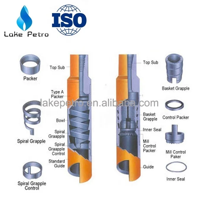
The basic overshot (from top down) consists of a top sub, a bowl, grapple, control, and a guide. In addition to the basic components, some overshots (Series 10 and 150) can be dressed with either a:Spiral grapple used if the fish diameter is near the maximum catch of the overshot, or a
The Series 150 Overshot features the ability to packoff on the fish. When the circulating packoff is not used, the fluid circulates down the drillpipe, aroundthe top outside of the fish, through the slip or grapple assembly, around the guide shoe and up the annulus.
When the circulating packoff is used, the annular space between the top outside of the fish and the inside of the lower part of the overshot is packed off, diverting the fluid flow down into the fish, making it easier to release and recover the fish. Packoffs usually are not high pressure devices but will often withstand sufficient pressure to establish circulation through the fish. Third party high pressure packoffs are available from various sources.
The extension can be installed between the top sub and the bowl of the Series 10, 70, and 150 overshots. It is used to extend the overshot bowl to:Allow the grapple to catch farther down on a fish that may be necked down at the top by having been pulled in two, or latched by an overshot and released several times, or to
A stop ring must be used where a fish OD reduces immediately below the catch area to allow the grapple to bite on full-size pipe.Example - catching a Hydril upset or EUE collar. If the upset of collar should pass completely through the grapple, the overshot may not be releasable.
If a stop ring is needed and the grappledoes not have a built-in stop, a stop ring can be run above the grapple, in the area between the Top Sub pin and the Grapple.
The Series 10 Sucker Rod Overshot is designed to engage and recover sucker rods, couplings, and similar items from inside tubing strings.Basket grapples are recommended for fishing for hardened and ground boxes (Sucker Rod Box).
The Series 20 Sucker Rod Overshot is a short catch tool which provides a means for engaging the exposed portion of a fish too short to be engaged with a Series 10 overshot.Uses basket grapples only
The Series 70 Short Catch Overshot is designed to engage the exposed portion of a fish too short to engage with Series 150 overshots.Uses basket grapple only
The Series 150 Releasing and Circulating Overshot is used to engage, packoff, and retrieve twisted-off lost tubing, drillpipecoupling, tool joint, casing or other similar fish.
Special Grapples:Nitraloy grapples may be available from some vendors. It is available only in the most popular sizes and is not commonly used on standard pipe.
A right hand wicker grapple converts a normal right release overshot to left hand release. This grapple is used where you expect to apply excessive right hand torque to release a packer, safety joint, etc. Note: Overshot will have to be released by left hand rotation.
Grapple Controls:Basket Grapple control packers have built in packoffs. These packoffs will hold various amounts of pressure, depending on the size of the fish and the condition of the packoff after engaging the fish.
High Pressure Packoff Assemblies:The High Pressure Packoff Assembly is an accessory to the Series 150 Overshots. It is used when high pressure circulation to the fish is required. It consists of a packoff sub with packing and packing rings and is installed between the top sub and bowl of the overshot. By running the packoff sub above the bowl, this design prevents the application of high internal pressures to the overshot bowl. The design of the High Pressure Packoff Assembly allows pressures two to three times the standard overshot packoff to be applied to the fish.
This information comes directly from the NOV manual for the Wide Catch Overshot. This is probably the first and only change to this common tool I know of in my career.
The Wide Catch Overshot provides the strongest tool available to externally engage, pack-off, and pull a fish that has been significantly worn. This tool has similar rugged design features and construction as the industry standard, Bowen Series 150 overshot, with the ability to interchange the Bottom Guide with the full range of existing components used with the standard Bowen Series 150 overshot.
In service, the Wide Catch Overshot (WCOS) takes a positive grip over a large area of fish and is capable of withstanding heavy pulling, torsion, and jarring strains without damage to the tools or the fish.
The WCOS has been designed to significantly increase the catch range of the OD of the fish to be caught, compared to the standard overshot. This enables a greater opportunity for a successful fishing operation in a reduced number of trips, thus reducing overall intervention costs for the operator. In addition to the large catch range, the WCOS has the ability to seal across very large extrusion gaps at both standard and high pressure and provide full circulation through the fish, should it be required.
New coarse threads have been introduced at the connection between the top sub and bowl to allow for quick assembly while maximizing the torsion and tensile strength.
Connections between the Top Sub/Bowl and Extension Sub have been designed to create a seal. This will prevent the connection from washing out should the overshot be required to be flowed through for a long period of time. In order to lock the Top Sub/Extension Sub to the Bowl from backing off during operation, set screws have become standard and will gall the threads should the connection break free.
The operation of all overshots is identical. The exception being that the Series 150 carries a packoff which provides circulation through the fish. First, determine that the overshot is properly assembled and dressed with the proper size grapple. Make up the overshot on the fishing string (normally it is run connected to the bottom of the bumper sub) and run it into the well. As the top of the fish is reached make sure circulation has been established to clear overshot ID of any plugging. Lower the overshot onto the top of the fish with no rotation at first. A 5,000 pound set down weight will be sufficient to engage the grapple. While lowering the overshot over the top of the fish watch for pressure build up, shut off pumps if any pressure build up is noticed. Should any back pressure be noticed, release the back pressure to allow the grapple to engage the fish. By elevating the string it can be determined, if the grapple went over and engaged the fish. If unable to work overshot over top of fish without rotation, then slowly rotate the fishing string to the right and gradually lower the overshot over the fish. Combined rotation and lowering over top of the fish are important to keep the grapple in the release position. This provides the maximum clearance between the grapple and fish. While lowering the overshot over the top of the fish, watch for torque build up and an increase in pump pressure. A pump pressure build up indicates the overshot has gone over the top of the fish thereby reducing the flow area. Stop rotation (continued rotation could dull the wickers of the grapple) enabling the grapple to set. Allow the right hand torque to slack out of the string and then pull on the string by elevating the string to set the grapple.
To release from the fish, bump down, then simultaneously rotate to the right and slowly elevate the fishing string. It is best to have a clean fishing top before running the overshot.
The present invention relates to an overshot tool having means for engaging and disengaging a latch in a core barrel head assembly used in core drilling operations and in particular although not exclusively to an overshot tool having an automated latching control mechanism to allow automated coupling and retrieval of the head assembly from within a bore hole. Background art
Diamond core drilling utilises an annular drill bit connected to a core barrel assembly. The core barrel is attached to the end of a number of tubular drill rods connected to form a drill string. The drilling progressively removes cylindrical cores of rock or material through which the drill and drill tube advance using a sequence of runs. This type of drilling utilises an inner tube assembly which has an inner tube connected to a head assembly to receive the core sample. The head assembly comprises a latch body connected to a valve housing which in turn is connected to a bearing housing which in turn is connected to an inner tube connector. The inner tube assembly connects to the inner tube connector and may comprise an inner tube, core lifter and core lift case. The inner tube assembly locates within a core barrel which comprises a combination of drill bit, reamer, outer tube, landing ring and locking coupling. The inner tube assembly can be retrieved from the surface when the inner tube is full. Empty inner tube assemblies can be delivered from the surface to the bottom of the drill string in order to recommence drilling.
The drill bit is advanced by rotating the drill string while applying downward pressure. In addition, drilling fluid such as water or drilling muds are pumped through the centre of the drill string, past the inner tube assembly and through the end of the drill bit in order to carry cuttings and other drilling debris to the surface via the annulus between the wall of the hole and the external surface of the drill string.
With either locating an inner tube assembly within a drill string or retrieving an inner tube assembly, when the inner tube is full, it is most often the case that an overshot tool is used to either lower the inner tube assembly into place, be used to pump the inner tube assembly into place or be lowered by itself to retrieve the inner tube assembly. In the case of a dry hole, the overshot tool will hold the inner tube assembly and their combined weight will allow the inner tube assembly to be lowered into position. In the case of a wet hole, or where the hole is partially wet or where the hole is horizontal, inclined upwardly or upwardly vertical, then the overshot tool has a sealing section which is fluid tight and enables fluid pressure to push the overshot tool and the attached inner tube assembly along the drill tubing.
The overshot tool, when used to retrieve an inner tube assembly when the inner tube assembly is full, can either fall under gravity to latch with the core barrel assembly or again be pumped into place to latch with the core barrel assembly.
A conventional latch in an inner tube assembly of a smaller diameter comprises a pair of pivoted and opposed arms. The lower portions below the pivot point of the arms have a resilient or biasing means which draw the lower ends together. This in turn causes the upper ends of the latch members to project outwardly from the inner tube assembly. In this position they can engage with a locking coupling included in the core barrel to latch the inner tube assembly with respect to the core barrel.
The overshot tool needs to cooperate with this latch so that the inner tube assembly can be held with respect to the overshot tool when it is being placed into position within the drill string and core barrel or alternatively must cooperate with the latch when the overshot tool is being used to retrieve the inner tube assembly.
In the case of retrieval, the overshot tool needs to engage the latch so that it releases the inner core assembly from the core barrel while at the same time the latch also needs to engage the overshot tool so that the overshot tool is held by the core barrel latch which allows for withdrawal of the inner tube assembly from the drill tube.
Various means exist for performing all of the above functions. However, it is the case that there are a number of different pieces of equipment that are used depending on the type of hole being drilled. The hole may be wet or dry and it may be vertically down or vertically up or any inclination in between. This means that the set of equipment, being the inner tube assembly and overshot tools differ in their configuration and operation depending on the type of hole being drilled.
Certain objects and advantages of the present invention will become apparent from the following description taking in connection with the accompanying drawings, wherein, by way of illustration and example, and embodiment of the present invention it is disclosed. Summary of the Invention
It is an objective of the present invention to provide an overshot tool configured to cooperate with a latch mechanism of a head assembly via an automatic coupling/decoupling engagement such that the tool may be coupled to the head assembly and both components retrieved from the borehole quickly, conveniently and reliably. It is a further specific objective to provide an arrangement that provides both automated and manual decoupling of the tool from the head assembly to allow detachment by personnel at the surface and decoupling down the hole when the overshot tool is used to deliver the head assembly into the final latched position at the cutting end of the core barrel apparatus.
It is a further specific objective to provide an overshot tool that is sensitive to the method of delivery down the borehole so as to provide a feedback signal to an operator that the tool has reached its desired destination at the head assembly. It is a further specific objective to provide an overshot tool that is resistant to decoupling from the head assembly when used to deliver the head assembly into position should the assembly encounter obstructions during delivery.
The automated coupling and decoupling function of the present overshot tool is provided by primary and secondary engaging portions where at least one of the engaging portions is controlled by a latch control that is responsive to the environment in which the tool is placed and additionally the forces acting on the tool. Accordingly, the latch control is configured to control an axial and optionally a rotational movement of the primary and secondary engaging portions. The coupling and decoupling is achieved specifically via engagement by the primary engaging portion (to provide coupling) and the secondary engaging portion (to provide decoupling). The specific activation of the secondary engaging portion is controlled by the latch control and is responsive to forces acting on the tool at the cutting end of the borehole where the head assembly is maintained or released at its latched position against the inner surface of the core barrel. Additionally, the specific objectives are achieved by providing a latch control that is conveniently implemented as a pin and slot arrangement acted on by a bias member that is configured to provide from either an axially forward or rearward end.
Preferably, the housing comprises a slot in which the first and second parts of the housing comprise regions of the slot and the retainer is capable of movement within the slot between the first and second parts. Preferably, the bias member is configured to bias the secondary engaging portion rotatably relative to the primary engaging portion. Preferably, the bias member is a coil spring extending between the housing and the secondary engaging portion. Such an arrangement is advantageous to provide a reliable and robust configuration for the latch control mechanism that provides the automated or semi-automated latching of the secondary engaging portion and hence a coupling and decoupling action of the tool.
Preferably, the tool further comprises a cover member to accommodate the primary and the secondary engaging portions and the housing wherein the primary and secondary engaging portions and the housing are capable of sliding axially within the cover member. The cover member acts to protect the inner components of the tool and to allow the various components to slide axially and rotate circumferentially around the axis in use.
Optionally, the tool further comprises a temporary rotational lock having at least two locking positions to temporarily lock the housing at the cover member at two rotational positions. The rotational lock is configured to provide quantised default positions of the secondary engaging portion relative to the housing and the primary engaging portion. Accordingly, a degree of force is required to adjust the releasable lock between the two positions so as to change the state of the tool to be configured for latching or unlatching of the head assembly. Such force may be provided by the pressure of a supply fluid or the weight of a free fall delivery assembly acting on the overshot tool.
Preferably, the cover member comprises a cut-out positionable at the same axial and rotational position as the slot of the housing. The cut-out is configured to allow the pin of the latching mechanism to project through the wall of the cover member such that the cover member does not obstruct the latching mechanism and in particular the pin that extends radially outward from the primary engaging portion.
Preferably, the retainer is fixed to and projects radially from the shaft and through the slot in the housing wherein the bias member is configured to force rotational and axial movement of the retainer within the slot. Accordingly, the retainer forms a radially extending region of the shaft such that rotational and axial adjustment of the retainer provides a corresponding movement of the shaft relative to the other components of the tool. The relative position of the shaft is therefore determined by the relative position of the retainer within the various slots and channels of the present overshot tool.
Preferably, the first part at the slot extends in a circumferential direction to receive the retainer and the second part at the slot comprises an axially extending length section being greater than a length section of the first part. Accordingly, the retainer is configured to travel circumferentially and axially within the slot.
Optionally, an engaging end of the primary engaging portion comprises a bayonet configuration at a leading end of the tool being engagable with the latch; and an engaging end of the secondary engaging portion comprises a bell portion to engage the bayonet configuration in touching or near touching contact and release the bayonet configuration from engagement with the latch. Such an arrangement is advantageous to engage a particular configuration of latch at the head assembly that may comprise resiliently biases latching arms having engaging ends movable radially inward and outward.
Preferably, the housing of the tool comprises a coupling portion at a trailing end of the tool to mate with a valve housing or a free fall overshot attachment, the coupling portion capable of sliding axially within the housing and independently of an axial movement of the primary engaging portion. The present tool therefore is configured to mate with an overshot attachment or a valve housing to allow the tool to be both delivered and extracted from the borehole when coupled or decoupled from the head assembly. The latch control of the tool is configured to be sensitive to the coupling state of the valve housing or overshot attachment at the tool to both provide a feedback signal to an operator at surface level and to change the coupling state of the tool to either couple or decouple at the head assembly.
Preferably, the shaft comprises a channel recessed into a radially outward facing surface of the shaft, the channel having a first part aligned axially with the shaft and a second part extending circumferentially around the shaft, a radially inner part of the retainer configured for slidable engagement within the first and second parts of the channel. The channel in cooperative engagement with the retainer acts to restrict relative movement of the shaft both in an axial and rotational direction. Accordingly, the second engaging portion and the primary engaging portion are configured to move relative to one another by a limited range of movement both in the axial and circumferential or rotational directions via various slots and channels as described herein.
In one embodiment, the overshot tool has a first means for engaging a latch in a head assembly, the latch locking to the first means when engaged, and latch control means associated with the first means which is movable with respect of the first means wherein, in a first position, the latch control means allows the first means to engage the latch, and in a second position, the latch control means opens the latch to release the first means from the latch.
The first means on the overshot tool may comprise a number of different arrangements for connecting to the latch in the head assembly. Preferably the first means may comprise a spike which locates into and engages with the latch in the head assembly. Other arrangements may be suited to the first means and will depend on the type of latch used in the head assembly. For the sake of clarity, the first means will be described in the remainder of the specification as comprising a spike, however it will be realised that the invention is not to be restricted to this particular feature.
The latch may comprise a conventional dual arm latch where each arm is diametrically opposed to the other and pivotally secured with respect to the head assembly. However, other latch arrangements such as three of more latch arms or an alternative style of latch would be equally suited to this invention. For example, 4 or 6 arms may be used with larger diameter drilling systems.
In preference, the latch comprises at least two opposed and pivoted latch arms having inner ends that are biased towards one another to push the upper ends outwardly to abut with a locking coupling in a core barrel. The biasing means may comprise an elastomeric member located around the inner ends of the latch arms which acts to draw them together. This in turn causes the outer ends to pivot outwardly with respect to the head assembly.
The spike preferably has a tip that is shaped to that it will pass through the centre of the latch assembly so that the latch moves to allow the tip portion to pass through and, once the tip portion has passed the ends of the latch, the latch arms then closed behind the tip portion to thereby retainably engage the spike. In this position, with the latch engaged on the spike, the upper ends of the latch arms are withdrawn inwardly towards the head assembly so that they will disengage from the locking coupling and allow the inner tube assembly to move within the drill tube. This therefore allows the overshot tool to either retrieve an inner tube assembly by unlocking the latch from the locking coupling or lower the inner tube assembly into the drill tube by having the upper ends of the latch arms withdrawn from their latching position.
There will be a number of different circumstances where the spike is to be disengaged from the latch. It will need to occur at the surface when the inner tube assembly is manually removed from the end of the drill tubing or it will need to occur remotely once the inner tube assembly has landed at the end of the drilling tube which is known as a dry release. It may also need to occur when the inner tube assembly is part way into the hole.
In all cases, the latch control means operates to disengage the latch from the spike to thereby allow separation of the overshot tool from the inner tube assembly. In the case of when the overshot tool is delivering the inner tube assembly to the end of the drill string, this must be achieved remotely and at the surface, the manual disengagement must allow for easy and safe disengagement.
Preferably, the movement of the latch control means can be initiated remotely from the surface. When the overshot tool is returned to the surface it can be operated manually in a manner that is quick and convenient for an operator and does not involve any potential for injury to be caused or for any loss of or damage to the inner tube assembly.
The latch control mean means preferably slides along the outer surface of the spike and further, preferably comprises a sleeve journalled for sliding movement along a shaft of the spike. The end of the latch control means preferably engages with the arms of the latch to open the lower ends of the latch arms against the resilient biasing member to thereby allow the tip of the spike to be withdrawn from the latch.
Preferably, the latch control means has an intermediate position between the first and second positions where the latch control means acts to prevent the latch from opening to thereby inadvertently release the spike. Preferably, the latch control means is provided with an abutment surface that locates adjacent the upper ends of the latch arms that thereby prevent inward movement of the upper ends of the latch arms. By preventing this inward movement, the latch cannot be released from the spike.
Further, the abutment surface, when the latch control means moves to its second position, locates within an area where there is sufficient clearance between the upper ends of the latch arm and the abutment surface to allow movement of the upper ends of the latch arms inwardly to thereby release the forward ends of the latch arms from the spike. Brief description of drawings
A specific implementation of the present invention will now be described, by way of example only, and with reference to the accompanying drawings in which: Figure 1 shows a cross-section view of an overshot assembly comprising an overshot tool and a valve housing,
Figures 6a and 6b show cross-section views of an overshot tool and valve housing and show the overshot tool releasing from the latches of an inner tube assembly,
Figures 10a and 10b show cross-section views of an overshot tool and valve housing assembly engaged with an inner tube assembly to locate the inner tube assembly in a drill string,
Figures 12a and 12b show the overshot tool connected to an inner tube assembly in preparation for delivery of the inner tube assembly to the core barrel of a drill string,
Figure 12c shows a part view of the overshot tool and the position of the retainer mechanism for delivery of an inner tube assembly into a drill tube,
Figure 13c shows a part view of the release mechanism part way through the operation of the release mechanism, and Figures 13a and 12b show the overshot tool as it relates to the position of the release member shown in Figure 14c, and
Figure 14c shows the release mechanism in the position where the overshot tool is released from the core barrel head and Figures 14a and 14b show the overshot tool as it relates to the position of the release member shown in Figure 14c.
Figure 1 shows an overshot assembly which is an assembly of an overshot tool 10 and valve housing 11. The overshot tool 10 is used to retrieve an inner tube assembly. It can also be used to deliver an inner tube assembly to the end of a drill string. The valve housing 11 can be used to pump the overshot tool 10 through a drill string. This will normally be to retrieve the inner tube assembly. The valve housing 11 is provided with seals 12 which provide flexible fluid seals between the valve housing 11 and the inner wall of the drill tube. An indicator valve 13 is provided within the valve housing 11 to provide an indication to the driller when movement of the valve housing 11 ceases. The indicator valve 13 is shown in Figure 1 in its open position and comprises a ball 14 and fluid flow ports 15. In its open position, the indicator valve allows fluid that is pumped in behind the valve housing 11 to flow through opening 16 and the fluid flow ports 15. In its closed position and in order to pump the valve housing 11 along drill tubing, the ball 14 is set behind valve seat 17 which prevents fluid flow through the valve housing 11 and therefore enables fluid pressure to move the valve housing 11 along the drill tube (as shown in figure 3a).
Upon the valve housing 11 becoming stationary as would be the case when the overshot tool 10 engages an inner tube assembly, an increase in fluid pressure will cause the ball 14 to move through the valve seat 17 from the position of figure 3a to its position of Figure 1 so that the fluid ports 15 are now open and allow fluid to freely flow forward of the valve housing 11 and around the overshot tool 10. This change in pressure provides an indication at the surface to the drill operator that the overshot tool 10 has landed. The valve housing 11 has a wire rope connector 18 to which a retrieval wire rope is secured. This enables the overshot tool 10 and valve housing 11 combination to withdraw an inner tube assembly from the drill hole. The valve housing 11 is secured to the overshot tool 10 either threadably or by a pin or both. The overshot tool 10 comprises a spike 20 and a latch control means 21. The latch control means 21 has an axial bore through which a portion of the shaft of the spike 20 locates. The spike 20 and latch control means 21 are located within a housing 22 and the housing 22 is in turn located within a cover member 23.
The latch control means 21 comprises a sleeve within which a portion of the shaft of spike 20 is slidably journalled. As will be explained below, the latch control means 21 moves to various positions along the spike 20 to control operation of a latch, and that movement is controlled by a retainer 24 which is threadably mounted with respect to the latch control means 21. An end 25 of the retainer 24 projects from the inner bore of the latch control mean 21 and is selectively locatable within either a longitudinal slot 26 or circumferential slot 27 which are both located on the spike 20 as shown in figure 8. The shaft of the retainer 24 locates within a control slot 29 which is located within the wall of the housing 22. The head 30 of the retainer 24 projects above the outer surface of the housing 22 and locates generally within a cut out 31 within the cover member 23. As will be explained below, the head 30 will in certain circumstances abut against an edge of the cut out 31.
A spring 32 is connected to both the housing 22 and the latch control means 21. It provides both a compressive and torsional force to the latch control means 21. The spring 32 is compressed and normally provides a force that pushes the latch control means 21 away from the housing 22. The spike 20 has a tip 35 that comprises a conical portion 36 and a circumferential ledge 37. The conical portion 36 and ledge 37 are designed to engage with the latch in the inner tube assembly. The spike 20 is journalled for sliding movement within a bearing 39 in the housing 22. The spike 20 is retained within the housing 22 via a pair of bolts 40 that threadably engage the end of the spike 20. The heads of the bolts 40 are located within slots 41 which in turn allows a small amount of longitudinal movement of the spike 20 with respect to the housing 22. When the end 25 of the retainer 24 is located within the circumferential slot 27 on the shaft of the spike 20 then the spring 32 acting on the latch control means 21 will in turn bias the spike 20 into its forward position shown in Figure 2. When the end 25 of the retainer 24 is located within the longitudinal slot 26 on the spike 20, the spring 32 will push the latch control means 21 forward so that the bell portion 43 locates over the head portion 44 of the spike 20. The latch control means 21 has an abutment collar 45 which cooperates with the latch in the head assembly and its operation is described below.
Figure groups 4 to 7 show the engagement of the overshot tool 10 with an inner tube assembly. The Figures show a head assembly 47 and do not include the inner tube in which the sample is collected. The inner tube is threadably connected to an end of the head assembly 47. The head assembly 47 combined with the inner tube is referred to as the inner tube assembly.
Figures 4a and 4b show the overshot tool 10 that has been pumped into a hole and has just engaged with the latches 48 of the head assembly. The latches 48 comprise a pair of arms 49 that are pivotally connected to the head assembly 47 via pivots 50. The inner ends 51 of the latch arms 49 locate behind the ledge 37 on the spike 20. An elastomeric o-ring 52 locates around the inner ends 51 and bias the inner ends 51 so that they engage against the head portion 44 of the spike 20. This holds the inner ends against the ledge 37 to thereby hold the latch 48 in a closed position with respect to the spike 20. The arms 49 have upper ends 53 which abut with the locking coupling of a drill string (not drawn) to hold the head assembly 47, in its drilling position where it is positioned to receive core sample as drilling progresses. In order for the upper ends 53 of the latch 48 to engage with locking coupling in the core barrel, the upper ends 53 need to project radially outward to a greater extent than what is shown in figure 4b. The diameter of the head portion 44 of the spike 20 is sized so that the inner end 51 are pushed outwardly against the O ring 52 to thereby retract the upper ends 53 to the position shown in Figure 4b. This retracted position of the upper ends 53 provides clearance both with respect to the locking coupling and the inner wall of the drill tubing.
The example shown in Figures 4a, 4b, 4c, 5a, 5b, 5c and 5d are where the overshot tool 10 is required to be pumped into position which may be the case in respect of a wet hole where a column of water is maintained within the drill tube. It may also be the case in respect of a horizontal or upwardly inclined hole. Generally, it is required in a hole that is not sufficiently vertical (in the downward direction) to allow free fall of the inner tube assembly and associated overshot assembly.
Figure 4c illustrates the setting of the cover member 23 for retrieval. Figures 4a and 4b show the overshot tool 10 just as it connects to the head assembly 47 that is to be retrieved. The tip 35 of the spike 20 pushes through the inner ends 51 of the arms 49 to thereby unlatch the head assembly 47 from the locking coupling of the core barrel. The latch 48 is now engaged with the spike 20 with the inner ends 51 of the arms 49 located behind the ledge 37.
Prior to sending the overshot tool 10 into the drill tube to retrieve the head assembly 47 the latch control means 21 is positioned with respect to the housing 22 so that the retainer 24 is in the position shown in Figure 4c. In addition, the cover member 23 is rotated so that a slot 61 in the cover member 23 is not aligned with the slot 60 of the control slot 29. This is a pre-loaded position so that the spring 32 holds the retainer 24 in this position. When the spike 20 engages with the latch 48 the fluid pressure continues to act on the valve housing 11 and there is simultaneous operation of both the indicator valve 13 and the retainer 24 associated with the latch control means 21. Both of these things occur substantially simultaneously.
In the case of the indicator valve 13, the pressure will be sufficient to force the ball 14 through the valve seat 17 to the position shown in 4a, 3b and 3c. The valve seat 17 is a polymer and is sufficiently resilient to enable movement of the ball 14 at a predetermined pressure. This release of the ball 14 opens the fluid ports 15 which will enable fluid to flow through the valve housing 11. The valve arrangements within the head assembly 47 will be closed which will prevent fluid flow and allow the overshot tool 10 and valve housing 11 to be pumped through the drill string. Upon reaching a halt, the ball 14 moves through the valve seat 17 and causes a momentary pressure spike which provides an indication to the operator at the surface that the overshot tool 10 has landed.
At the same time, the spike in fluid pressure results in the valve housing 11 pushing the housing 22 and cover member 23 forward towards the head assembly 47 so that the housing 22 is caused to move in relation to both the latch control means 21 and spike 20. Engagement of the end 25 of the retainer 24 within the circumferential slot 27 results in the spike 20 and latch control means 21 moving rearwardly as is shown in Figure 5d. This in turn causes the spring 32 to be compressed and for the retainer 24 to be moved rearwardly in relation to the control slot 29. It reaches the end of edge end 55 of the control slot 29 and the torsional force exerted by spring 32 causes the latch control means 21 to rotate so that retainer 24 moves into slot portion 60. This is illustrated in Figure 5d where the latch control means 21 is now able to move longitudinally with respect of spike 20 as a result of the end 25 now engaging the longitudinal slot 26. This moves the latch control means 21 to the positions shown in Figure 5b where the abutment collar 45 blocks any further inward movement of the upper ends 53 of the latch arms 49. This is the intermediate position of the latch control means 21 and physically prevents any movement of the outer ends of the latch 53 inwardly and thereby prevents any disengagement of the inner ends 51 of the latch arms 49 from the tip 35 of the spike 20.
Once the latch control means 21 rotates so that the retainer 24 is within slot 60 of the control slot 29, the spring 32 acts to push the latch control means 21 forward and the retainer 24 slides within slot 60 until it abuts against edge 62 of the cut out 31 in the cover member 23. This is illustrated in Figure 5d. In this position, the spring 32 continues to apply force to the latch control means 21 so as to hold the retainer 24 against the edge 62.
The release of the indicator valve 13 provides an indication to the driller at the surface that the overshot tool 10 has engaged the head assembly 47. As the latch control means 21 will have operated automatically, then the combination of the overshot tool 10 , valve housing 11 and inner tube assembly will be ready for removal. In order to release the overshot tool 10 from the head assembly 47 upon arrival of the combination of the overshot tool 10, valve housing 11 and inner tube assembly to the surface, the cover member 23 is rotated so that the slot 61 and the cover member 23 aligns with slot 60 in the housing 22. This results in spring 32 pushing the latch control means 21 fully forward to its second position where it disengages the spike 20 from the latch as previously described above. The rotation of the cover member 23 is illustrated in Figure 6c and the release position is shown in Figures 6a and 6b.
This allows a very convenient and safe release of the overshot tool 10 from the head assembly 47. This release is illustrated progressively in Figures 7a, 7b, 7c and 7d where the bell portion 43 of the latch control means 21 locates over the head portion 44 of the spike 20 such that the end of the bell portion 43 abuts against the ledge 37. In this position, the outer surface of the bell portion 43 abuts against the inner surfaces of the latch arms 49 adjacent the inner ends 51 of the latch arms 49 so that the inner ends 51 move away from the head portion 44 and out of engagement with the ledge 37. Once the inner ends 51 of the arms 49 no longer engage the ledge 37 then as seen in Figures 7a, 7b, 7c and 7d, the overshot tool 10 can be withdrawn from the latch 48 and the end of the head assembly 47.
Figures 8 and 9 show more clearly the relationship of the longitudinal slot 26, circumferential slot 27 and retainer 24. As can been seen in, for example, Figure 12c, when the retainer 24 is located in the three shorter lengths of the control slot 29, that are parallel and proceed slot 60 that cause back and forth movement of the retainer 24 portion of the control slot 29, the end 25 of the retainer 24 will be in the circumferential slot 27 and thereby lock movement of the latch control means 21 with respect to the spike 20. However, when the retainer moves into slot 60 out of the three shorter lengths of the control slot 29 (as shown in Figure 9), then the end 25 aligns with the longitudinal slot 26 which then frees the latch control means 21 to move longitudinally with respect of the spike 20. This enables the latch control means 21 to move between its first and second position and also an intermediate position as will be described below.
It may also be possible to use the overshot tool 10 and valve housing 11 to connect to an inner tube assembly at the surface and then pump this combination through the drill string. This is not necessary in general practice, but is possible with the overshot tool 10 connected to the head assembly 47 as shown in Figures 10a and 10b it would be possible to deliver an inner tube assembly to the end of the drill rods if required. The part conical portion 36 bears against a surface 54 within the head assembly 47. This enables the overshot tool 10 to push against the head assembly 47 while the latch 48 prevents release of the overshot tool 10. In this position, the overshot tool 10 combined with the valve housing 11 could be used to pump the inner tube assembly into the end of the drill string. This is generally not required, as the inner tube assembly itself would normally, in certain types of holes, be pumped into the drilling position. But as explained below, this invention is capable of being used in this way.
In this configuration, the combination of the inner tube assembly, overshot tool and valve housing 11 can be inserted within the upper end of the drill tube and then pumped into place. In this case a stuffing box is located on the end of the drill tube which enables fluid to be pumped into the drill tube behind the valve housing 11. The stuffing box is designed to allow a wire rope connected to the wire rope connector 18 to be fed into the drill tube as the combination advances to the end of the drill tube.
The combination will eventually reach the position where the inner tube assembly will latch into its drilling position. Once the inner tube assembly stops moving, the fluid pressure behind the valve housing 11 will increase and exert pressure which will result in both operation of the indicator valve 13 in the valve housing 11 and forward movement of the housing 22 with respect to the spike 20. Both of these operations occur substantially simultaneously.
In relation to the indicator valve 13, the fluid pressure is sufficient to push the ball 14 through the valve seat 17 to thereby open the fluid flow ports 15 this is as previously described and illustrated in Figures 3a, 3b and 3c. At the same time, the housing 22 moves with respect of the spike 20. The spike 20 is in the position shown in Figure 6b. In this position, the bolts 40 are at the upper ends of the slots 41. As the end 25 of the retainer 24 is located within the circumferential slot 27, then movement of the spike 20 also results in movement of the latch control means 21 which is effectively locked with respect to the spike 20. This causes movement of the retainer 24 so that the head abuts against the end 55 of the control slot 29. Once the retainer 24 reaches the end 55 of the control slot 29 the torsional force applied to the latch control means 21 by the spring 32 causes the latch control means 21 to rotate so that the retainer 24 locates within slot potion 60. In this position, the end 25 of the retainer 24 aligns with the longitudinal slot 26 in the spike 20 and allows the latch control means to slide forwardly with respect to the spike 20.
Once in the slot portion 60, the compressive force applied by spring 32 pushes the latch control means 21 forward and as the end 25 of the retainer 24 is in the longitudinal slot 26 and the head 30 locates within slot 61 of the cover member 23, then the latch control means 21 moves from its first position as shown in Figures 10a and 10b to a second position where the latch control means 21 acts to open the latch 48 to thereby release the spike 20 as previously described and with reference to Figures 7a, 7b, 7c and 7d. The overshot tool 10 and valve housing 11 are then free to be returned to the surface by winching in the wire which is connected to the wire rope connector 18. The core barrel assembly is now latched in position where the upper ends 53 of the arms 49 are now engaged with the locking coupling and thereby latch the inner tube assembly into place. With the overshot tool 10 released from the latch 48, then it is free to be returned to the surface.
The overshot tool 10 may also be used for lowering an inner tube assembly into a dry hole where there is no fluid within the length of the drill tube or where the drill tube may only be partially filled. In this case, instead of using a valve housing 11 a free fall attachment 65 is connected to the overshot tool 10. This is illustrated in Figure 11. The free fall attachment 65 has a series of guide rollers 66 that assist movement of the combination through the drill tube. Importantly, the weight of the free fall attachment 65 is sufficient to compress the spring 32. Accordingly, when the inner tube assembly latches in place, the weight of the free fall attachment 65 will cause movement of the housing 22 and cover member 23 with respect to the latch control means 21 and spike 20. However, while the combination of the free fall attachment 65, overshot tool 10 and inner tube assembly is suspended from the winch wire (attached to wire rope connector 18) there will be no relative movement between the housing 22 and the latch control means 21.
Prior to inserting the inner tube assembly into the drill tube, the position of the latch control means 21 is pre-set to the extreme end of the control slot 29 as shown in Figure 12c. This position provides a degree of safety as it will require two separate operations to release the overshot tool 10 from the head assembly 47. This prevents accidental release of the overshot tool 10 in the case where the progress of the inner tube assembly through the drill tube is interrupted. Clearance between the landing seal 56 and the inner surface of the drill tube is not great and all that may be required to jam the progress of the inner tube assembly would be some deposits on the inner surface of the drill tube or some damage to the inner surface of the drill tube. If this occurs, then the full weight of the free fall attachment 65 will be applied to the overshot tool 10 which will result in the latch control means 21 indexing through the first section of the control slot 29. The first application of the weight of the free fall attachment 65 will result in the housing 22 moving downwardly which in turn results in the retainer 24 moving to end 67 of the control slot 29 as seen in Figure 12c. Once in this position, the torsional force applied by spring 32 will result in the latch control means 21 rotating and bearing against end 67 of the control slot 29 as seen in Figure 12c. Once the cessation of movement of the inner core assembly is sensed at the surface, the cable is winched in and the weight of the free fall attachment 65 is removed from the overshot tool 10. However, the retainer 24 goes to the position shown in Figure 4c and the overshot tool 10 is not released from the head assembly 47. This then allows the driller to again lower the core barrel assembly in attempt to bypass the obstruction. If it does bypass the obstruction, then it can continue to its landing position at the end of the drill rods. However, if it again jams, then the weight of the free fall attachment 65 will act to release the overshot tool 10 from connection to the head assembly 47. In this case at least the overshot tool 10 and free fall attachment 65 can be recovered and then an attempt can be made to retrieve the inner tube assembly.
It is also possible that the inner tube assembly may be released from the overshot tool upon reaching water in a partially water filled hole. As the inner tube assembly with the attached overshot tool and free fall attachment 65 are lowered into the water, the movement of all of these components will be impeded. This will be sensed at the surface by the winch cable becoming slack.
At the same time, the weight of the free fall attachment 65 and overshot tool will operate the latch control by indexing it through the first section of the control slot 29. The inner tube assembly could now be released by a further tensioning of the cable and a subsequent release of the cable which in turn will result in the weight of the overshot tool 10 and free fall attachment 65 which will then result in release of the overshot tool from the inner tube assembly. The inner tube assembly will then be free to float to its latched position within the core barrel and while this is occurring, which will take some time, the operator can retrieve the overshot tool 10 by winching it out of the hole. This will obviously save some time as the overshot tool 10 may be out of the drill tube by the time the inner tube assembly latches into the core barrel.
In a fully dry hole, the inner tube assembly will latch into drilling position with the latch control means 21 and retainer 24 in the position shown in Figure 12c. Once in this position, then it will be necessary for the driller to lift the free fall attachment 65 and overshot tool 10 twice in order to release the overshot tool 10 from the latch 48 as the process of attachment will have resulted in the weight of the overshot tool 10 and free fall attachment 65 already indexing the retainer once as shown in Figure 13c. This release is illustrated progressively in Figures 13a, 13b and 13c where Figure 13c shows the retainer 24 located at the end of both slot 60 and 61 which results in the latch control means 21 moving to its second position as shown in Figure 13b where it releases the overshot tool from the head assembly 47. This then allows the overshot tool 10 and free fall attachment 65 to be retrieved to the surface.
The free fall attachment 65 combined with the overshot tool 10 can also be used to lower an inner core assembly fully into a hole which is partially wet. In this case, the combination of the overshot tool 10, free fall attachment 65 and inner tube assembly will be lowered via the winch cable until the combination contacts the water within the drill tube. At this point, movement of the combination may be retarded by the water however it will still continue to fall under its own weight with the overshot tool 10 and free fall attachment 65 connected. Similarly, the weight of the free fall attachment 65 will be sufficient to operate the latch control means 21 and retainer 24 in the matter described above when the inner tube assembly reaches the core barrel.
As will be appreciated from the above description, the invention provides useful means of controlling the operation of an overshot tool 10 to both retrieve and deliver an inner tube assembly into and out of a core barrel. Further, the set of tools described above can be used both in relation to wet and dry holes and can also be used either in relation to pumping in or lowering under gravity. This will be a significant advantage to drillers who prior to this invention were required to carry multiple sets of tools for either circumstance. This invention provides a unified set of tools which can be used in both applications.
It will be appreciated by those skilled in the art that the invention is not restricted in is use to the particular invention described. Neither is the present invention restricted in its preferred embodiment with regard to the particular elements and/or features described or depicted herein. It will be appreciated that the invention is not limited to the embodiment or embodiments disclosed, but is capable of numerous rearrangements, modification and substituents without departing from the scope of the invention.

Open hole fishing is one of the most time consumed operation because it involves a lot of unknown down hole conditions. In order to have successful fishing operation, it is imperative to fully understand about the open hole fishing tool. The video training below provided by Weatherfor is considered as one of the best fishing operation video training. Additionally, the full video transcription is provided to help people understand this topic.
Open hole fishing involves the removal of unwanted objects from the wellbore. The objects can be tools, equipment, and broken pieces of drill, pipe, bits or tribunals. Open hole fishing begins following a backoff and a drill string at or above the stock point of the fish in the wellbore leaving an accessible fish top. The fish can be removed using special tools and techniques.
A screw-in sub is one of the most common fishing tools. Its modified pin can be used to catch an undamaged fish. The overshot tool because of its versatility is frequently used in fish recoveries. Its simple design included circulating and releasing action as well as a 360 degree catch of the fish.
Normally, the overshot or screw in sub is connected to the bottom of the bumper sub and fishing jars on the fishing assembly. As the tool is lowered over the fish, the top of the fish passes through the tool into the ball. When the assembly is raised, grapples engage the fish at a lower point and it is worked free and pulled upward. If the top of the fish is bad, twisted or broken, it should be dressed off to provided clean top so grapple can insecurity firmly. Dressing off is achieved with a skirted or hollow food mill. Several types of mills are available for this purpose and other jobs.
In a washed-out hole, use of a hydraulic knuckle joint located above the overshot kicks out under pump pressure to increase the sweep of the overshot to facilitate capture of an elusive fish. With a severe washout, a wall hook guide run on the bottom of the overshot, further improves the search and capture of the fish. When the fish cannot be dislodged by pulling with the overshot, a jarring assembly run in the fishing strain can be activated to strike heavy blows either up or down on a stock fish to freak. The down action is achieved with a bumper jar, essentially a slip joint with a sliding stroke. The impact, enhanced by the weight of drill collars above the bumper jar results in a sharp blow with the fishing string. Dropping the string quickly produces a sharp downward blow on the fish. This jarring action is especially effective in free e-seated pipe or a string that is stuck as a result of an upward blow.
The impact produced by hydraulic jar depends on the amount of pulled taken on the tour before it drips. As indicated earlier, the impact of a hydraulic jar is enhanced by the weight of drill collars placed above the tool. A jar accelerator further intensifies the effect of a jar at any depth. It is especially effective in shallow fishing operations where elasticity present in longer drill strings is not in any way. The use of an accelerator also keeps the energy of the jar impact from being lost up hole.
When a fish is stocked in and cannot be jarred or work free, a widely used practice called washover is employed. The washover operation is the most successful way of freed of fish and requires expert judgment both in pipe selection and in its proper running applications. As modern whole conditions are critical, in many cases of bit drip may be necessary to condition the hole prior to running the washpipe.
Essentially, washover operations involve a pipe string that slips over a stuck fish allowing fluid to circulate in the annulus between the fish in the inner wall of washover pipe. Fluid under pressure flushes out debris cut loos by the rotary shoe run on the bottom of the washover pipe. The washed over fish secured by an overshot or screw in sub and then he backed off and removed to the surface. The washover pipe selected requires an inside diameter large enough to accommodate the fish and an outside diameter they can rotate without sticking in the open hole and still allow circulation.
Various types of weatherford rotary shoes are available. Each shoe is custom designed for a particular procedure. Tooth-type shoes for example, are recommended when the formation to be cut is relatively soft. When metals such as tool joints or stabilizer blades must be cut, the rotary shoe is dressed with tungsten carbide or diamonds internally, externally or both, tailored specifically. And improper choice could severely damage the fish, complicating the recovery operation. Occasionally with drill pipe maybe plug usually by m


 8613371530291