
overshot water wheel design brands

Water wheel design has evolved over time with some water wheels oriented vertically, some horizontally and some with elaborate pulleys and gears attached, but they are all designed to do the same function and that is too, “convert the linear motion of the moving water into a rotary motion which can be used to drive any piece of machinery connected to it via a rotating shaft”.
Early Waterwheel Design were quite primitive and simple machines consisting of a vertical wooden wheel with wooden blades or buckets fixed equally around their circumference all supported on a horizontal shaft with the force of the water flowing underneath it pushing the wheel in a tangential direction against the blades.
These vertical waterwheels were vastly superior to the earlier horizontal waterwheel design by the ancient Greeks and Egyptians, because they could operate more efficiently translating the hydrokinetic energy of the moving water into mechanical power. Pulleys and gearing was then attached to the waterwheel which allowed a change in direction of a rotating shaft from horizontal to vertical in order to operate millstones, saw wood, crush ore, stamping and cutting etc.
Most Waterwheels also known as Watermills or simply Water Wheels, are vertically mounted wheels rotating about a horizontal axle, and these types of waterwheels are classified by the way in which the water is applied to the wheel, relative to the wheel’s axle. As you may expect, waterwheels are relatively large machines which rotate at low angular speeds, and have a low efficiency, due to losses by friction and the incomplete filling of the buckets, etc.
The action of the water pushing against the wheels buckets or paddles develops torque on the axle but by directing the water at these paddles and buckets from different positions on the wheel the speed of rotation and its efficiency can be improved. The two most common types of waterwheel design is the “undershot waterwheel” and the “overshot waterwheel”.
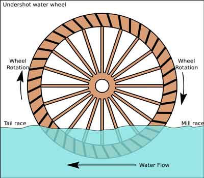
The Undershot Water Wheel Design, also known as a “stream wheel” was the most commonly used type of waterwheel designed by the ancient Greeks and Romans as it is the simplest, cheapest and easiest type of wheel to construct.
In this type of waterwheel design, the wheel is simply placed directly into a fast flowing river and supported from above. The motion of the water below creates a pushing action against the submerged paddles on the lower part of the wheel allowing it to rotate in one direction only relative to the direction of the flow of the water.
This type of waterwheel design is generally used in flat areas with no natural slope of the land or where the flow of water is sufficiently fast moving. Compared with the other waterwheel designs, this type of design is very inefficient, with as little as 20% of the waters potential energy being used to actually rotate the wheel. Also the waters energy is used only once to rotate the wheel, after which it flows away with the rest of the water.
Another disadvantage of the undershot water wheel is that it requires large quantities of water moving at speed. Therefore, undershot waterwheels are usually situated on the banks of rivers as smaller streams or brooks do not have enough potential energy in the moving water.
One way of improving the efficiency slightly of an undershot waterwheel is to divert a percentage off the water in the river along a narrow channel or duct so that 100% of the diverted water is used to rotate the wheel. In order to achieve this the undershot wheel has to be narrow and fit very accurately within the channel to prevent the water from escaping around the sides or by increasing either the number or size of the paddles.
The Overshot Water Wheel Design is the most common type of waterwheel design. The overshot waterwheel is more complicated in its construction and design than the previous undershot waterwheel as it uses buckets or small compartments to both catch and hold the water.
These buckets fill with water flowing onto the wheel through a penstock design above. The gravitational weight of the water in the full buckets causes the wheel to rotate around its central axis as the empty buckets on the other side of the wheel become lighter.
This type of water wheel uses gravity to improve output as well as the water itself, thus overshot waterwheels are much more efficient than undershot designs as almost all of the water and its weight is being used to produce output power. However as before, the waters energy is used only once to rotate the wheel, after which it flows away with the rest of the water.
Overshot waterwheels are suspended above a river or stream and are generally built on the sides of hills providing a water supply from above with a low head (the vertical distance between the water at the top and the river or stream below) of between 5-to-20 metres. A small dam or weir can be constructed and used to both channel and increase the speed of the water to the top of the wheel giving it more energy but it is the volume of water rather than its speed which helps rotate the wheel.
Generally, overshot waterwheels are built as large as possible to give the greatest possible head distance for the gravitational weight of the water to rotate the wheel. However, large diameter waterwheels are more complicated and expensive to construct due to the weight of the wheel and water.
When the individual buckets are filled with water, the gravitational weight of the water causes the wheel to rotate in the direction of the flow of water. As the angle of rotation gets nearer to the bottom of the wheel, the water inside the bucket empties out into the river or stream below, but the weight of the buckets rotating behind it causes the wheel to continue with its rotational speed.
Once the bucket is empty of water it continues around the rotating wheel until it gets back up to the top again ready to be filled with more water and the cycle repeats. One of the disadvantages of an overshot waterwheel design is that the water is only used once as it flows over the wheel.
The Pitchback Water Wheel Design is a variation on the previous overshot waterwheel as it also uses the gravitational weight of the water to help rotate the wheel, but it also uses the flow of the waste water below it to give an extra push. This type of waterwheel design uses a low head infeed system which provides the water near to the top of the wheel from a pentrough above.
Unlike the overshot waterwheel which channelled the water directly over the wheel causing it to rotate in the direction of the flow of the water, the pitchback waterwheel feeds the water vertically downwards through a funnel and into the bucket below causing the wheel to rotate in the opposite direction to the flow of the water above.
Just like the previous overshot waterwheel, the gravitational weight of the water in the buckets causes the wheel to rotate but in an anti-clockwise direction. As the angle of rotation nears the bottom of the wheel, the water trapped inside the buckets empties out below. As the empty bucket is attached to the wheel, it continues rotating with the wheel as before until it gets back up to the top again ready to be filled with more water and the cycle repeats.
The difference this time is that the waste water emptied out of the rotating bucket flows away in the direction of the rotating wheel (as it has nowhere else to go), similar to the undershot waterwheel principal. Thus the main advantage of the pitchback waterwheel is that it uses the energy of the water twice, once from above and once from below to rotate the wheel around its central axis.
The result is that the efficiency of the waterwheel design is greatly increased to over 80% of the waters energy as it is driven by both the gravitaional weight of the incoming water and by the force or pressure of water directed into the buckets from above, as well as the flow of the waste water below pushing against the buckets. The disadvantage though of an pitchback waterwheel is that it needs a slightly more complex water supply arrangement directly above the wheel with chutes and pentroughs.
The Breastshot Water Wheel Design is another vertically-mounted waterwheel design where the water enters the buckets about half way up at axle height, or just above it, and then flows out at the bottom in the direction of the wheels rotation. Generally, the breastshot waterwheel is used in situations were the head of water is insufficient to power an overshot or pitchback waterwheel design from above.
The disadvantage here is that the gravitational weight of the water is only used for about one quarter of the rotation unlike previously which was for half the rotation. To overcome this low head height, the waterwheels buckets are made wider to extract the required amount of potential energy from the water.
Breastshot waterwheels use about the same gravitational weight of the water to rotate the wheel but as the head height of the water is around half that of a typical overshot waterwheel, the buckets are a lot wider than previous waterwheel designs to increase the volume of the water caught in the buckets.
The disadvantage of this type of design is an increase in the width and weight of the water being carried by each bucket. As with the pitchback design, the breastshot wheel uses the energy of the water twice as the waterwheel is designed to sit in the water allowing the waste water to help in the rotation of the wheel as it flows away down stream.
Historically water wheels have been used for milling flour, cereals and other such mechanical tasks. But water wheels can also be used for the generation of electricity, called a Hydro Power system.
By connecting an electrical generator to the waterwheels rotating shaft, either directly or indirectly using drive belts and pulleys, waterwheels can be used to generate power continuously 24 hours a day unlike solar energy. If the waterwheel is designed correctly, a small or “micro” hydroelectric system can produce enough electricity to power lighting and/or electrical appliances in an average home.
Look for Water wheel Generators designed to produce its optimum output at relatively low speeds. For small projects, a small DC motor can be used as a low-speed generator or an automotive alternator but these are designed to work at much higher speeds so some form of gearing may be required. A wind turbine generator makes an ideal waterwheel generator as it is designed for low speed, high output operation.
If there is a fairly fast flowing river or stream near to your home or garden which you can use, then a small scale hydro power system may be a better alternative to other forms of renewable energy sources such as “Wind Energy” or “Solar Energy” as it has a lot less visual impact. Also just like wind and solar energy, with a grid-connected small scale waterwheel designed generating system connected to the local utility grid, any electricity you generate but don’t use can be sold back to the electricity company.
In the next tutorial about Hydro Energy, we will look at the different types of turbines available which we could attach to our waterwheel design for hydro power generation. For more information about Waterwheel Design and how to generate your own electricity using the power of water, or obtain more hydro energy information about the various waterwheel designs available, or to explore the advantages and disadvantages of hydro energy, then Click Here to order your copy from Amazon today about the principles and construction of waterwheels which can be used for generating electricity.

The Fitz waterwheel Company started in the summer of 1902. Its history leading up to this date started back in 1840 when Samuel Fitz operated the Hanover Foundry. This machine shop provided a number of services ranging from casting of segment and spur gears to metal parts needed in outfitting horse wagons in addition to building wooden waterwheels.
Around 1850, while running the Hanover factory, Samuel Fitz took over the Tuscarora Iron Works from Daniel Kennedy who had died at a young age. By this time wooden waterwheels were being made with metal hubs and axles. Some all metal waterwheels were also being made in England and finding their way to the United States. The advantage of having an "All Metal Waterwheel" was better machinery efficiency performance and simpler maintenance. Metal waterwheels also allowed the milling of products longer into the winter because the wheels would not freeze up. The performance increase was due to a curvilinear bucket (rounded shape). This type bucket reduced the turbulence of the water entering the bucket cavity, it also held the water longer in the buckets increasing the time duration of wheel cycle and had less water spillage. John Fitz (the son of Samuel) made his mark by being able to set up his machine shop to fabricate these metal water wheels using mass production processes. He had developed a standard metal bucket for a full range of wheel sizes, defined side panels to fixed sizes and an onsite assembly procedure that allowed most owners to assemble their new wheels with little assistance from a technician traveling in for site assembly. In looking at his machine shop work orders, even the total count and sizes of the rivets needed were detailed for each waterwheel order.
The Hanover factory and the Tuscarora Iron Works merged to form the I-X-L Water Wheel Company. Fitz had bought the name IXL from a turbine company he acquired around 1870 - 1880. If you look at it you see the phrase "I excel". By the late 1800"s the company was in full production of a full line of sizes of the world famous I-X-L Steel Overshot Water Wheel. In addition, the company continued to manufacture and restore all types of waterwheels. Fitz even manufactured wooden wheels for those clients who were committed to this type of wheel. The company continued to grow and on July 15, 1902 the company changed its name to the Fitz Water Wheel Company of Hanover, PA.
Fitz was a master when it came to marketing his products. He would produce and widely distribute his bulletins where he would present pictures of his waterwheels in many different locations doing a full assortment of jobs. He would go on page after page with countless letters of praise by their owners on how their new water wheel was the greatest investment they had made to their company. In almost all his advertising, you would see many pages describing why metal waterwheel was far superior to wooden wheels.
One of the main reasons for the success of the Fitz Water Wheel Company was not in its advertising but in the product itself. The first Fitz wooden wheels had a power efficiency of around 70%. Not bad for the time. With the introduction of the I-X-L Overshot Waterwheel, Fitz claimed over 90% efficiency. Fitz made sure he told the world about his great efficiency rating after a 136 page report was conducted in 1898 by the University of Wisconsin, Engineering School, and was posted to the public in 1913. By the late 1920"s the Fitz Water Wheel Company was the largest vertical waterwheel manufacturer in the world. Unlike turbines that lost their effectiveness with a small shift of water pressure, vertical waterwheels would continue to run in a low water volume situation. This made them ideal for factories and farms where water tables would vary widely during the year and product production was needed all year.
Fitz not one to miss all avenues of profit, understood what situations in the field a turbine was the better product to use. I say this because most of his advertisement presented a negative picture of turbines in general. Back in 1860"s he started to market the Burnham Turbine. Fitz later improved on that design and called it the Fitz-Burnham Turbine. By the 1930"s the company had a full line of turbines like the "Fitz Michell Hydraulic Turbine", the Ruralite and the "Fitz Hanover Turbine".
As the 1930"s passed and steam, diesel and gas engines took over the market place for power generation, Fitz continued to stay in business selling his wheels in the United States. By this time a good percentage of his business was in wheel restoration. He had also opened up the hydro market to sales in South American and in Europe.
Despite fewer new waterwheel sales, the company continued in business through the 1940"s by utilizing the machine tools it had to produce waterwheels, into making other machine parts. This can be seen by the number of orders placed by the air force in machine parts needed for aircraft. It also ventured in making portable turbine generators used during World War II.
To guess at a total number of wheels Fitz made is almost impossible. It would be safe to say over a few thousand just in the upper southeast of the US would be a good starting number. Chances are, when you run across a metal water wheel it will be a Fitz wheel. Fitz however, was not the only manufacturer of metal waterwheels. Campbell and Savage Water Wheel Company were two companies that shared a small percentage of metal waterwheels in this country. It is interesting to note that Campbell before starting his company worked for the Fitz Company for awhile.
In 1984 a research hobbyist, R.L. Omland wrote a series of four articles for the Society for the Preservation of Old Mills on the Fitz waterwheel and the mathematics behind the wheel. Some of his statements he made are represented here:
Because most Fitz wheels have a standard bucket design you can figure that for every 1 ft of width of the bucket you will be able to handle 2.7 cfs of water.
The number of buckets on a waterwheel is relative to the circumference of the wheel in feet, and that the spacing for buckets should be about 1 foot apart. One can use the following in determining the number of buckets (n) in a wheel. (n) = Pi * (D)iameter of the wheel. Once you know (n) you can determine the spacing (s) by using s = (pi*D)/n.
HorsePower at the shaft of a waterwheel can be determined by knowing the (D)iameter of the wheel, (Q)uanity of water in cfs [Cubic Feet/Second] by a constant of .1135 times the efficiency of the waterwheel. So HP = .1135 *Q*D*Eff

All collectionsThis collectionAlexis du Pont stereoviews and lantern slidesAmalgamated Leather Companies, Inc. photographs and labelAmerican Brewer journalAmerican Car and Foundry Company World War II era photographsAmerican Iron and Steel InstituteAnne Louis de Tousard journal and letter bookAssociated Factory Mutual Fire Insurance Companies maps and plansAssociation Against the Prohibition Amendment postcards and stationeryAtlantic Aviation Corporation photographsAutomatic Merchandising Company albumAvon ProductsBeauties of the Brandywine stereographsBeer and craft brewing oral history interviewsBerkshire Knitting Mills photograph albumBethlehem Steel Company collectionsBetter Living magazineBorn digital publicationsBrandywine Valley oral history interviewees" photographsBuckley Music System, Inc. albumBudd Company photograph collectionBureau of Standards fire test of steel furniture albumBusiness Screen MagazineCanada Dry beverages sales albumCape Charles, Virginia, historic photographsCarol Litchfield collection on the history of saltCarter Litchfield history of fatty materials collectionsCavalcade of America photographsCentennial Exhibition photograph and ephemera collectionChamber of Commerce of the United States photographs, videos, and publicationsCharles Blasius & Sons piano factory photographsCharles Findeisen aerial photographsCharles H. DeMirjian collection of DuPont Consumer Products Division photographs and ephemeraCinecraft Oral HistoriesCinecraft Productions FilmsCivil War collectionsConference Board audio recordingsConrail photographs and filmsConsolidation Coal Company annual reportsCrawford H. Greenewalt"s Manhattan Project laboratory notebooksCulley Family Cinecraft Productions CollectionDallin Aerial Survey Company PhotographsDavid H. Cope photographsDavid Sarnoff LibraryDelaware School Auxiliary Association photographsDelaware State Fair albumsDelaware, Lackawanna & Western Railroad Co. Coal Department photographsDisposor Corporation albumDu Pont Motors, Inc.DuPont Building construction and Hotel du Pont photographsDuPont Company Brandywine powder yards and neighboring worker communities" photographsDuPont Company External Affairs Department photograph fileDuPont Company Museum collectionDuPont Company South San Francisco Plant photograph collectionDuPont Company Textile Fabrics Department videotapesDuPont Company films and commercialsDuPont Fabrikoid portfolio, sales promotion and development illustrationsDuPont MagazineDuPont Powder Yards – World War IDuPont Product Information photographsDupont Textile Fibers Product Information collectionE.I. du Pont de Nemours & Company Advertising Department recordsE.I. du Pont de Nemours & Company World"s Fair albumsE.I. du Pont de Nemours & Company and du Pont family collectionsE.I. du Pont de Nemours & Company employees, 19th centuryE.I. du Pont de Nemours & Company photographsE.I. du Pont de Nemours & Company recordsE.I. du Pont de Nemours & Company, Inc., Carney"s Point Works and workers" housing panoramic photographsE.N. McConnell Restaurant photographsEdmond Rhett du Pont photograph collectionEdward J.S. Seal Photograph CollectionEleuthera Bradford du Pont CollectionEleutherian Mills Historical Library DedicationEleutherian Mills-Hagley Foundation research reportsElizabeth Webb travel journalErnest Dichter papersFairmount Park glass plate negativesFederal Reserve Bank of New York educational comicsFerracute Machine Company photograph collectionFilm and VideoFingerman collection of ephemeraFloyd Hollenbeck sales kit for Hanes Hosiery Mills Co.Frank E. Schoonover negativesFrank R. Zebley photograph albumsFrederick O. Barnum III collection of RCA Victor Company negativesG. C. Murphy Company store windows and interior photographsGabrielle Josephine Crofton diariesGenevieve Pittner collection of roller skating rink stickersGrace Hopper and Women Computer ProgrammersGray & Rogers Inc. advertisements for GritHagley Digital ArchivesHagley Library Published CollectionsHagley Museum and Library publications archiveHagley area and Charles Copeland estate photographsHagley portrait fileHagley reference fileHanfordHarlan & Hollingsworth Corporation cost book photographsHay"s Fruit Juice Company albumHenry C. Walton diary, 1875-1880Herbert Belar papersHerbert H. Harwood, Jr. collection of railroad negativesHerbert S. Winokur, Jr., Enron Board Records CollectionHistory of Kevlar oral history interviewsHologic Digital Mammography oral historiesHoopes Brothers & Darlington Inc. photograph collectionHudson Maxim collectionsIndiana Ordnance Works, Ballistics Lab photographsInnovation: the Journal of the Industrial Designers Society of AmericaInside Brown America newsletterInterstate Commerce Commission railroad abandonment indexJames Watson & Sons Co. photograph collectionJames Zellner glass plate negativesJoe Weisbecker CollectionJohn B. Stetson Company photographsJohn E. du Pont collection of Austin and du Pont families" photographsJohn Gordon Rideout negativesJohn J. Raskob papersJohn McShain photographsJohn Okolowicz collection of publications and advertising on radio and consumer electronicsJohn W. Macklem collection of DuPont Company powder yards photographsJoseph Bancroft & Sons Company / Miss America CollectionJoseph T. Richard records on Pennsylvania RailroadJoshua Conner & Son leather goods store photographsKeith Reeves Rodney diaries, 1905Kelvinator Corporation electric refrigerators albumKen White Associates, Inc. recordsLammot du Pont, Jr. aeronautical collectionLammot du Pont, Sr., papersLehigh Valley Railroad glass plate negativesLetterpress copybook of E. E. Hendrick, 1899-1903Locomotive Coaling Stations, Link-Belt Co. booklet of cyanotype photographsLocomotives and views of Mauch Chunk contact photographs and negativesLongwood ManuscriptsLouis E. and Max Levy photograph albumLouise Crowninshield gardenLukens Steel Company newslettersLukens Steel Company photographsMCI Communications CorporationMaps and Plans of the Hagley Site and BuildingsMarshall B. Johnson research collection of industrial design and housewaresMartha Furnace daybook/diaryMary Belin du Pont recipe bookMaryland Steel Co. photograph albumMatheson Automobile Company photographsMaxim Silencer Company photographsMerchants Coal Company photographsMid-Century Cocktail CultureMidvale Steel Company plant albumMidvale Steel and Ordnance Company motion picture filmsMorris travel albumsMorse Dry Dock DialNation"s Business MagazineNational Association of ManufacturersNational Automobile Dealers AssociationNational Electrical and Radio Exposition albumNational Urban League publications, 1930-1960New York Tunnel Extension of the Pennsylvania Railroad albumNewport NewsNiagara Falls Power Company power generation facility photograph albumNora C. Edwards papersNylonOral Histories on Z. Taylor VinsonOral HistoryOral histories on work and daily life in the Brandywine ValleyOral history interviews on Wallace CarothersOral history interviews on cultivated mushroom industryOral history interviews with John J. Raskob familyOral history interviews with former employees of DuPont Company"s Textile Fibers DepartmentOtis Elevator Company installation of electric lifts for the London Underground photographsP.S. du Pont (1870-1954)P.S. du Pont Longwood photographsPQ Corporation photographic collectionPSFS BuildingPenn Virginia Corporation photograph collectionPennsy magazine negativesPennsylvania Railroad Company. A history prepared by Coverdale and ColpittsPennsylvania Railroad negativesPennsylvania Railroad women workers oral historiesPew Charitable Trusts recordsPhiladelphia Division of the Pennsylvania Railroad, Main Line bridge photographsPhiladelphia and Reading Coal and Iron Company photographsPhiladelphia railroad stations, Red Arrow Lines trolley track and bus photographsPhoenix Bridge Company photograph collectionPhotographs of DuPont Company exhibits at Atlantic City, Wilmington, and elsewherePierre A. Gentieu Brandywine River Valley photographsPierre A. Gentieu papers, 1858-1911Plymouth Cordage Company albumPostcard views of John B. Stetson plantPostcards of motels, roadside attractions, restaurants, etc. in the United StatesProject Brandywine : Aerial Images of the Brandywine River ValleyPromotional comic booksPublic Affairs Committee pamphletsPusey and Jones Corporation photographsRCA Computing CollectionRadio Corporation of America, RCA Victor Division recordsRailroad station postcards collectionRalph Yourison Dupont Company retirement scrapbook, 1963Raymond Loewy CollectionsReading Company file related to the Pinkerton Detective AgencyRobert E. Wilhelm, Jr. collection of Red Clay Valley materialsRobert K. Austin picture file on the history the automobile in AmericaS.S. White Dental Manufacturing Company photograph collectionSeagram Spotlight photograph collectionSewing Machine TimesSheet MusicSimon B. Camacho papersSooy Brothers Memoirs, Victor Talking Machine Co.Sperry Corporation, UNIVAC DivisionSponsored and industrial motion picture film collectionStephanie Kwolek photographsStereo photographs of Longwood GardensStrawbridge & ClothierStrawbridge & Clothier"s Store ChatSubject and Media GallerySun-Maid Raisin Maidens photographsTaylor-Wharton Iron and Steel Company filmsTeflonThe Mill at Anselma oral history interviewsThis is Du PontThomas C. Marshall photographsThos. Moser Cabinetmakers recordsTrade catalogs and pamphletsUnited States Air Mail Service photographsUniversal DesignVulcan Iron Works negativesW.C. Spruance Lantern Slide CollectionWaldron collection of Christmas and holiday postcardsWard and Gow elevated railway and subway advertising albumWarren-Ehret Company photographsWawa, Inc. Public Relations photographs and audiovisual materialsWawaset Park photographsWestinghouse Electric Corporation Steam Division photographsWestinghouse Machine Company albumWestmoreland Coal Company photographsWhitaker family photographsWilliam H. Rau lantern slidesWilliam Henry Radebaugh filmsWilliam Pahlmann papersWilliam du Pont, Jr. papersPierre Samuel du Pont de Nemours and family papersWomen"s Handicraft in the 19th CenturyWoodlawn Trustees, Incorporated photographsWorkplace posters in the United StatesWorld War I motivational broadsidesYork Oil Burner Company"s industrial oil burning equipment albumZ. Taylor Vinson collection of transportation ephemera

Freeflow69 are happy to design water wheels for any site installation, just let us have the site details, water flow and head and we can give advice on the wheel required. Where a water wheel is not the appropriate equipment for a specific location, we can advise on other products and provide the installation design. For example; Cross Flow Turbine, Pelton Wheel or Axial Flow Turbine.
Here we have a breast shot wheel for a "run of river" installation (2.7metre diameter x 2 metre wide).The project Involved the design, manufacture and commissioning of this medium head Zuppinger enclosed type water wheel, It is now installed and running.

Water wheels are generally perceived as being inefficient energy converters which belong to the past, with no role for the future. But as Gerald Müller, Klemens Kauppert and Rüdiger Mach explain, they can actually be efficient and cost-effective in low head micro hydro applications
IN EUROPE, a large number of low head micro hydro power sites (head = <5m, power = <100kW) exist. Water power was a prime power source during the industrial revolution and thousands of water mills were built at low head sites. Today however, the large majority of such hydro power sources is not exploited due to the lack of a cost-effective hydraulic power converter. Recently, a number of developments appear to have opened up the possibility to generate electricity economically at low head sites. These developments include the two oldest hydraulic machines, namely water wheels and the Archimedian screw - the latter working in reverse as a power source rather than as a pump.
Water wheels are today often considered to be relics from the beginning of the industrial revolution; romantic but inefficient hydraulic machines made of wood and belonging to the past. It is generally believed that turbines are much more efficient than water wheels and subsequently took over their role as hydraulic power converters. The statistics however show a different picture. In Bavaria - a German province with an area of 70,500km2 - there were 7554 operational water wheels counted as late as 1927, with power outputs ranging from 0.75 to 75kW. In the middle of the 19th century, a high stage of development was reached when Zuppinger designed the most modern and efficient water wheel. Engineers, manufacturers and mill owners must have regarded water wheels as commercially interesting power sources. During the 1940s however, virtually all water wheels seem to have disappeared.
Today, some companies in Germany (Bega, Hydrowatt) and the US (Water Wheel Factory) are again manufacturing water wheels for electricity generation. The performance characteristics of such wheels still appear to be largely unknown. Assessment of the available power potential, comparisons with other turbine types such as the Kaplan or the Ossberger (crossflow) turbine, and even the determination of optimum operating conditions for water wheels, relies on estimates.
"Modern" water wheels, ie water wheels built using scientific principles, are made of steel and employ only the potential energy of the water since in low head flows the potential energy exceeds the kinetic energy of the flow by far. These water wheels can be divided into three fundamental types:
Water wheels were, in the large majority of cases, used to drive machinery and reached efficiencies of 75-89%. This development seems to have subsequently been forgotten.
In Karlsruhe, Germany, a small non-profit research company (IFMW - Institut für Forschung und Medien im Wasserbau) has been set up which specialises in hydraulic engineering research, and in particular in the development and promotion of low head hydro power. Within the company, a very detailed literature and market review on water wheels was conducted in order to assess the suitability of water wheels for electric power production. Since only over and undershot wheels are currently built, the discussion will be limited to those two types.
The overshot wheel receives its feeding water at the top of the wheel, catches the water in buckets or "cells" and releases the water at the lowermost possible elevation. In order to make maximum use of the energy contained in the water, the cells are shaped so as to receive the water at its natural angle of fall and then to retain it as long as possible.
Some measurements of the performance characteristics of overshot wheels were conducted in 1928, as shown in the figure below. It was found that the efficiency of a water wheel reaches 85%.
The undershot wheel was developed for the utilisation of very low heads from 0.5-2m. Whereas in ancient times the kinetic energy of the flow was utilised with a paddle-type wheel, "modern" undershot wheels built after Zuppinger"s design employ the potential energy only. The figure below shows a Zuppinger wheel with the typical "backwards" inclined curved blades.
Wheel diameters range from 4-7m, with head differences from 0.5 to 1.5m. The blades are arranged in a way so as to avoid losses at the water entry, then gradually reduce the head of water in each cell and finally to discharge the water, again with a minimum of losses. The wheel blades are curved to allow for a gentle decrease of the water level from upstream to downstream, and to minimise losses at the downstream end. In an engineering textbook from 1939 it was stated that efficiencies of 76% can be guaranteed for properly designed undershot wheels.
Recently, the undershot wheel has also experienced a small renaissance. Hydrowatt has built and installed 15 Zuppinger wheels over the last nine years, with diameters ranging from 4-7.5m, and widths of 0.5-3m. Hydraulic heads utilised ranged from 1-2.2m, with typical flow rates of 1.5-3.1 m3/sec, giving power outputs from 4-45kW of electrical power. The overall efficiency (from hydraulic power available to electric power out) was estimated as ranging from 60 to 65%.
In the UK, many smaller streams were made navigable by building weirs, many of which still exist. Generally, the head differences were in the range between 1.2-1.8m. The undershot wheel may offer a possibility to produce electric power from such weir sites. The picture below shows a typical weir situation (Eel weir on the Lagan river in Northern Ireland) with a virtual water wheel inserted. The water wheel actually fits into a "natural" environment very well, indicating that a modern machine can become a visually attractive feature too.
The Archimedian screw has been known since antiquity as a simple machine for the lifting of water. Today, Archimedian screws are still in widespread use as pumps for sewage, grain and so on. It has the advantage of being a very simple machine, with only one moving part and two bearings. It was however only recently noticed that the screw could also - in its reverse role - be employed as energy converter, termed hydraulic screw. Large scale experiments with a hydraulic screw of 8.6m length and 2.35m drop were conducted at Prague Technical University in the Czech Republic in order to assess the performance of the hydraulic screw in its power generation mode.
The screw shown in the picture above was designed for a maximum flow rate of Qmax = 0.35 m3/sec. In experiments, it reached an efficiency of 70% for Q/Qmax = 0.4, and 80% for 0.6 < Q/Qmax < 1.0. The screw rotates at 53rpm, so that fewer gear ratios than for a comparable water wheel are required to achieve the speed necessary for electricity generation. To the author"s knowledge, six hydraulic screws have been installed already. Some design guidance for hydraulic screws, based on the design experience with screw pumps and generator experiments, is also available.
The economics of micro hydro converters are a function of variable boundary conditions such as electricity prices and so on. In Germany, overshot water wheels are currently built (including installation and grid connection) for 4360-4850 US$/kW. Undershot wheels cost 7760-9700 US$/kW, Archimedian screws approximately 8250-8730 US$/kW installed capacity. For comparison, low head Kaplan turbines cost 14500-15500 US$/kW. Although water wheels and the Archimedian screw have significant cost advantages over turbines, micro hydro installations are economical only if the owner uses the generated electricity at least partially, such as for a small business. Assuming 50% of self use, 6000 hours of operation per year at nominal capacity, a small business electricity price of 11 c/kWh and a price of 7.3 c/kWh for electricity fed into the grid, the following pay back periods apply:
The general perception amongst the public as well as many engineers is that water wheels are inefficient energy converters and belong to the past. Water wheels, and in particular the overshot variety, are however very efficient and cost-effective energy converters for low head micro hydro power applications. Today, the wider application of water wheels seems to suffer from a lack of information on water wheels, the lack of any design guidance and - possibly the most important aspect - the lack of actual data about the performance of such wheels.
Apparently, no performance data at all exists for undershot wheels, whereas some information is available on overshot wheels in old reports. IFMW Karlsruhe is currently conducting a detailed review and analysis of the experimental data available on overshot wheels with a view to application of such wheels for electricity generation.
The determination of performance characteristics for overshot wheels, and the publication of such data, will be the next task of the company, followed by a detailed evaluation of undershot wheels.
The use of the Archimedian screw for power generation is a recent idea. A lot of data and design expertise does however exist from the application of the Archimedian screw as a pump, and large scale experiments in the generator role were conducted so that the design methodology of Archimedian screws is quite developed.
Ecological aspects are today a major issue in the design of hydro power installations. Both the water wheel and the Archimedian screw are considered to be very fish friendly because of the large compartments for the water and the slow speed, even for long fish like eel, thus giving them a considerable advantage over the fast rotating Kaplan turbines.
Often seen beside a picturesque rural mill, an overshot water wheel possesses two excellent characteristics: considerable mechanical efficiency and easy maintenance. Many have remained in service for decades, and now lend a nostalgic charm to their surroundings.
Operated by gravity, the overshot wheel derives its name from the manner in which water enters the buckets set around its periphery. Pouring from a flume above the wheel, the water shoots into buckets on the down-moving side, overbalancing the empty ones opposite and keeping the wheel in slow rotation.
Since such a wheel may be located near but not actually in the stream, it offers endless landscaping possibilities for a country home where a stream with sufficient flow is available. If a site on dry ground is chosen, the foundation may be constructed dry and the water led to the wheel and a tailrace excavated. With very little effort, the scene may be turned into an attractive garden spot, the wheel becoming both a landscaping feature and a source of power.
It should be noted, however, that an overshot wheel is practical only for a small-capacity output. How much power it will produce depends upon the weight of water the buckets hold and its radius, or lever arm. Expressed in another way, the output depends upon the weight of water transported and the height, or head, through which it falls while in the buckets. For maximum efficiency, the wheel must use the weight of the water through as much of the head as possible. Therefore, the buckets should not spill or sling water until very near tail water.
Although of simple construction, an overshot wheel is cumbersome in size. For this reason, before attempting to build one be certain you have the facilities to move and lift it into place when completed. Also allow yourself plenty of working floor space. It must be understood, too, that such a wheel is a sizable project and requires a lot of material and time. Extreme care in cutting and assembling the parts is not essential, however, because the wheel, operating at slow speed, need not be accurately balanced.
Our construction plans are suitable for a small wheel suitable for a water head of 6′ 3″. The wheel itself has a diameter of 5′, leaving a flume head of 15″ to propel the water into the buckets. You may build the wheel to give a power output ranging from 1/2 hp. to 1 hp. at 10 r.p.m. All dimensions remain the same except the width, the horsepower increasing as this is increased. For 1/2 hp., the wheel should be 15 31/32″ wide. For 1 hp., it should be 31 29/32″. Before deciding on the wheel size, you’ll want to make a survey of the power available in the stream.
Virtually all large wheels are built with wood or steel arms and have a shroud plate only around the outer edge, but you may find it simpler and more satisfactory to build the drum-type wheel described here. In this case, each shroud plate is a disk of 1/8″ sheet steel. Each disk is braced by a 1/8″ sheet steel sole plate to which it is continuously welded, by the buckets, by one of the two large diameter 1/4″ steel hub flanges to which it also is continuously welded, and by the long hub itself.
If preferred, the shroud plates may be made of wood. If so, care should be taken to bolt them securely to the hub flanges. Bushings pressed into the wood for the bolts will give the wheel a longer life expectancy.
Sheet steel for the disks may be ordered direct from several large steel companies in case your local supply house is unable to furnish it. Ordinarily, such steel comes in standard 48″ widths, so you may have to weld together two or more sheets to get the required 5′ diameter, using either a butt weld or a backing plate. This will produce some distortion or ripple, as will the welding on of the numerous clips required. So long as distortion is local, however, and the main lines of wheel and shaft remain true, this will do no harm.
The buckets are the most important element of the wheel. To give maximum efficiency, they must be formed so that the water enters smoothly at the top of their travel and remains in them until just before they reach the bottom. For this reason, the bucket form we’ve indicated should be followed faithfully. Either sheet metal or wood is an acceptable material, but metal is better suited to cold climates, since wood is damaged when absorbed water freezes. Because the buckets are subject to wear from the water and sediment that it carries along, you may want to install them so they can be easily replaced.
Welding of the various parts of the wheel produces an exceptionally strong construction. After getting together or making all the required parts, begin the assembly by welding four clips to each end of the hub sleeve. Then weld the required number of clips to the shroud plates for the sole plate, and weld the shroud plates to the clips on the hub sleeve. After welding both hub flanges to the shroud plates and the sleeve with a continuous weld, attach the sole plate to the clips on the shroud plates with No. 8 self-tapping screws. Also weld the sole plate to the shroud plates with a continuous weld, and the bucket-support angles to the sole plate.
Although the wheel turns slowly, it is heavy and will be running almost constantly, so good lubrication of the bearings is essential. To this end, care should be taken to insure that the bearing liners are finished to the correct fit. Porous inserts or inserts containing graphite are excellent for this application, but may cost more than regular bearing inserts.
It is important that the foundation be carried deep enough so that water falling from the buckets will not undermine it. Avoid a long flume if possible, in order to keep the construction as simple as possible. Strengthen it along its entire length with an exterior frame and support it well from dam to wheel with pipe uprights.
The sluice gate may be located at any convenient place along the flume. Since it is the governing mechanism of the wheel, its installation should be anything but slipshod. If it is installed at an angle, water pressure will keep it at any desired position. If installed vertically, some mechanism, such as a rack and pinion, should be provided to keep it in place.
Adjust the sluice so that the buckets will run one-quarter full. This will give a wheel speed of 10 r.p.m. If the buckets are allowed to run more than one-quarter full, the efficiency of the wheel will drop for two reasons. Because of the increased speed, centrifugal force will throw water from the buckets. They also will begin to spill before approaching tail water. Although this practice does waste water, it may be profitably employed during a freshet to increase the power output, for at such times the excess water would be wasted anyway.

Years ago, in response to a customer"s request, I went looking for a reliable source of waterwheels for ornamental ponds and streams. You"ll love what I found!
Hand-crafted in Pennsylvania by a local Amish carpenter, these wooden waterwheels come complete with sealed wheel bearings and a cold-rolled steel axle. Screws and fasteners are yellow zinc coated. Yesteryear will come alive in your pond or stream when you find a creative way to include one of these beautiful turning waterwheels.
Please note that all of our Amish-made water wheels are overshoot wheels (the water is meant to flow into the wheel from the top just past the center point.) We do not have any undershot wheels, designed for the water to turn the wheel as it flows beneath them. We feel that an overshot wheel is more showy and traditional and are that for which the majority of our customers are looking.
Because of the inherent characteristics of wood, these waterwheels may include knots and other natural blemishes. Includes natural variations such that no two waterwheels will be identical.
The waterwheels rotate freely around a stationary axle, and as such are configured for decoration only, not for driving equipment. We recommend using with a 100gph pump for the best display. Wheel bearings are sealed and we do not recommend greasing, especially where they will be in contact with fish or other wildlife.
Important:All wooden products sold unfinished should be finished immediately with a paint or stain by the customer. No wood products should be left unfinished, as they are extremely susceptible, especially to humidity or water damage, in this state. Unfinished products should not be purchased unless adequate weather-safe storage is available while the product awaits treatment.

Overshot weaving is an American artform of the Appalachian region of the United States. Overshot’s geometry may be familiar because of its ubiquity in coverlet weaving in that area in the 18th century. Its origins go even further back, its motifs appearing in northern Europe, the Phillipines and ancient Persia.
Overshot is a weave structure, woven on four harness looms. It is typically composed of a plain colored, cotton or linen warp (the threads held under tension on the loom) and a colorful, woolen weft (the floating yarn, wound onto a bobbin and passed through alternating warp threads). The warp threads are tied onto the loom in a sequence that allows for floating, woolen wefts to create the stunning, optical effects that lend overshot its distinctive patterning.
I was invited to design this pattern for one of my all time, favorite yarn stores, Ritual Dyes, who generously supported me through the design process and supplied the absolutely wonderful yarn! This project was made for their Fall Equinox pattern release as a part of a kit. The kit includes the printed pattern, the yarn and a little gift, all housed within a beautiful, hand screen printed bag. Find the kit, while they last, here:


 8613371530291