
overshot water wheel design for sale
Overshot waterwheel A vertically-mounted wheel that is rotated by falling water striking paddles, blades or buckets near the top of the wheel is said to be overshot. In true overshot wheels the waters passes over the top of the wheel, but the term is sometimes applied to backshot or pitchback wheels where the water goes down behind the waterwheel.
Typical overshot wheels has the water channeled to the wheels at the top and slightly to one side in the direction of rotation. The waters collects in the buckets on that side of the wheel, making it heavier than the other "empty" side. The weight turns the wheels, and the waters flows out into the tail-water when the wheels rotates enough to invert the buckets. The overshot design can use all of the waters flow for power (unless there is a leak) and does not require rapid flow.
Unlike undershot wheels, overshot wheels gain a double advantage from gravity. Not only is the force of the flowing water partially transferred to the wheel, the weight of the waters descending in the wheel"s buckets also imparts additional energy. The mechanical power derived from overshot wheels is determined by the wheel"s physical size and the available head, so they are ideally suited to hilly or mountainous country.
Overshot wheels demand exact engineering and significant head, which usually means significant investment in constructing a dam, millpond and waterways. Sometimes the final approach of the wat ers to the wheel is along a lengthy flume or penstock.http://en.wikipedia.org/wiki/Wikipedia:Text_of_the_GNU_Free_Documentation_License
Sullivan"s waterwheels , A small family business, located in the South Carolina Foothills! We want everyone to be able to own a beautiful relaxing millwheel of their own! Whether it be for your garden,pond,or as a beautiful addition to any landscaping, home and garden & yard large are small. We strive to bring you the best.
The overshot wheel is the most common wheel seen in North America. It is a gravity wheel. This means that it harnesses the force of gravity acting vertically on the water as it travels from the top to the bottom of the wheel. Properly designed for a particular site, and correctly timed, an overshot The overshot wheel is most effective when it turns as slowly as possible and can still handle the total flow of water available to it. The optimal rim speed should be only about 3 feet per second. The larger the wheel the slower it will need to turn. The incoming water must be traveling about three times the rim speed of the wheel so that it can fill the buckets effectively. This requires a foot or more of head above the wheel, usually controlled by a gate.
When the head, or fall of water was not sufficient for a large diameter overshot wheel, the breast wheel often is used. This is halfway between the overshot and undershot wheels. Water strikes the buckets of the breast wheel about midway between top and bottom, using the weight of the water for a 90 degree segment of arc. Their efficiency is far less than the overshot, which uses the weight of the water for a full 180 degrees.
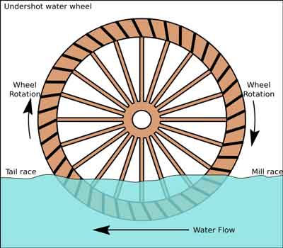
This type of waterwheel relies on the flow of water, coming along the base flowing at a good rate of speed to push or thrust the waterwheel. This type of waterwheel is used on mills built on rivers or streams that do not have any height or (head). Undershot wheels are normally narrow and have to have the channel walls very close to the sides of the wheel to maximize the flow of water to pass through the wheels to generate power. This type of wheel is generally the least efficient type of wheel - usually in the 30-50% range. The exception to this is the Poncelet wheel that can get up to 80% efficiency if the channel is properly constructed and the buckets are designed right.
This type of waterwheel relies on the flow of water, generally in an open stream. This type of wheel is generally the least efficient type of wheel - usually in the 30-40% range. The exception to this is the Poncelet wheel that can get up to 80% efficiency if the channel is properly constructed and the buckets are designed right.
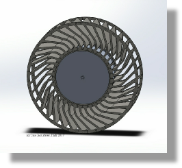
Many micro hydro electric generation strategies have evolved in recent years. Helical Ribbons, Under Water Blade Turbines, Tide and Wave action mechanical generators. Our approach is to simplify sustainable micro hydroelectric water wheel construction and improve the efficiency of energy generation. Our recent association with Ticho Industries in Italy has produced a new form of micro hydro waterwheels with a high efficiency electric generator mounted safely on the axle completely within the water wheel structure. This design simplifies micro hydro water wheel design for optimal water flow location mounting, system longevity, ease of maintenance and simplified electro mechanical connection. Our new design was created for city and rural stream based flows - including the outflows from major hydro electric dams, major navigation and irrigation dams, manufacturing and water treatment facilities.
To do this you will need to know two things, the quantity of water and the height of the water fall. From this you can determine the Horsepower at the axle of the waterwheel.
To get electricity out of a waterwheel you will have to gear the RPMs of the waterwheel (generally from 5-10 rpm”s up t0 500 - 1700 rpm’s) and then run it through a generator or a DC motor to charge a battery bank. This will generally cut your power at the axle HP by almost 1/3 to 1/2. A waterwheel is really designed to do mechanical work.

Here"s the famous Fitz Metal wheel that claimed 90% efficiency with curved paddles. Used on the majority of mills and other businesses powered by water. 24 paddles, brass bushing with 6" solid brass axle and assembled with 32 sets of brass screws and bolts. Wheel is laser cut from .060 whie styrene.Spokes set off from wheel.Wheel matches all 2" sluices.
This 2" wide wheel is wider than our previous resin cast. Has the detail of wooden wheel construction - 30 paddles in laser cut white styrene plastic.
Kit includes all the sluice details: Flow Control, Side Spill, sluice squares plus 4 sets of brass bolts/nuts for flow control. Side spill can be "either side". There"s a customizable end "square" to be drilled to insert you water source tubing. Feautres engraved sides with wooden board design.Fits 2" wide wheels.
Kit includes Styrene Sluice #4041 (above) PLUS 2 Bent-trestle with cross member in styrene. Sluice is removable (not attached) for easy cleaning of algae without removing mill or raceway/wheelposts.The bents fit into an "in stream" simplified raceway with smaller wheel post design (complete drawings included).
PLANS for 3-Story Waterwheel Mill are shown in 3 full pages sized 24" x 36" showing 1:24 scale CAD drawings at actual size.For Larger Click on Picture (right)
Water wheel design has evolved over time with some water wheels oriented vertically, some horizontally and some with elaborate pulleys and gears attached, but they are all designed to do the same function and that is too, “convert the linear motion of the moving water into a rotary motion which can be used to drive any piece of machinery connected to it via a rotating shaft”.
Early Waterwheel Design were quite primitive and simple machines consisting of a vertical wooden wheel with wooden blades or buckets fixed equally around their circumference all supported on a horizontal shaft with the force of the water flowing underneath it pushing the wheel in a tangential direction against the blades.
These vertical waterwheels were vastly superior to the earlier horizontal waterwheel design by the ancient Greeks and Egyptians, because they could operate more efficiently translating the hydrokinetic energy of the moving water into mechanical power. Pulleys and gearing was then attached to the waterwheel which allowed a change in direction of a rotating shaft from horizontal to vertical in order to operate millstones, saw wood, crush ore, stamping and cutting etc.
Most Waterwheels also known as Watermills or simply Water Wheels, are vertically mounted wheels rotating about a horizontal axle, and these types of waterwheels are classified by the way in which the water is applied to the wheel, relative to the wheel’s axle. As you may expect, waterwheels are relatively large machines which rotate at low angular speeds, and have a low efficiency, due to losses by friction and the incomplete filling of the buckets, etc.
The action of the water pushing against the wheels buckets or paddles develops torque on the axle but by directing the water at these paddles and buckets from different positions on the wheel the speed of rotation and its efficiency can be improved. The two most common types of waterwheel design is the “undershot waterwheel” and the “overshot waterwheel”.
The Undershot Water Wheel Design, also known as a “stream wheel” was the most commonly used type of waterwheel designed by the ancient Greeks and Romans as it is the simplest, cheapest and easiest type of wheel to construct.
In this type of waterwheel design, the wheel is simply placed directly into a fast flowing river and supported from above. The motion of the water below creates a pushing action against the submerged paddles on the lower part of the wheel allowing it to rotate in one direction only relative to the direction of the flow of the water.
This type of waterwheel design is generally used in flat areas with no natural slope of the land or where the flow of water is sufficiently fast moving. Compared with the other waterwheel designs, this type of design is very inefficient, with as little as 20% of the waters potential energy being used to actually rotate the wheel. Also the waters energy is used only once to rotate the wheel, after which it flows away with the rest of the water.
Another disadvantage of the undershot water wheel is that it requires large quantities of water moving at speed. Therefore, undershot waterwheels are usually situated on the banks of rivers as smaller streams or brooks do not have enough potential energy in the moving water.
One way of improving the efficiency slightly of an undershot waterwheel is to divert a percentage off the water in the river along a narrow channel or duct so that 100% of the diverted water is used to rotate the wheel. In order to achieve this the undershot wheel has to be narrow and fit very accurately within the channel to prevent the water from escaping around the sides or by increasing either the number or size of the paddles.
The Overshot Water Wheel Design is the most common type of waterwheel design. The overshot waterwheel is more complicated in its construction and design than the previous undershot waterwheel as it uses buckets or small compartments to both catch and hold the water.
These buckets fill with water flowing onto the wheel through a penstock design above. The gravitational weight of the water in the full buckets causes the wheel to rotate around its central axis as the empty buckets on the other side of the wheel become lighter.
This type of water wheel uses gravity to improve output as well as the water itself, thus overshot waterwheels are much more efficient than undershot designs as almost all of the water and its weight is being used to produce output power. However as before, the waters energy is used only once to rotate the wheel, after which it flows away with the rest of the water.
Overshot waterwheels are suspended above a river or stream and are generally built on the sides of hills providing a water supply from above with a low head (the vertical distance between the water at the top and the river or stream below) of between 5-to-20 metres. A small dam or weir can be constructed and used to both channel and increase the speed of the water to the top of the wheel giving it more energy but it is the volume of water rather than its speed which helps rotate the wheel.
Generally, overshot waterwheels are built as large as possible to give the greatest possible head distance for the gravitational weight of the water to rotate the wheel. However, large diameter waterwheels are more complicated and expensive to construct due to the weight of the wheel and water.
When the individual buckets are filled with water, the gravitational weight of the water causes the wheel to rotate in the direction of the flow of water. As the angle of rotation gets nearer to the bottom of the wheel, the water inside the bucket empties out into the river or stream below, but the weight of the buckets rotating behind it causes the wheel to continue with its rotational speed.
Once the bucket is empty of water it continues around the rotating wheel until it gets back up to the top again ready to be filled with more water and the cycle repeats. One of the disadvantages of an overshot waterwheel design is that the water is only used once as it flows over the wheel.
The Pitchback Water Wheel Design is a variation on the previous overshot waterwheel as it also uses the gravitational weight of the water to help rotate the wheel, but it also uses the flow of the waste water below it to give an extra push. This type of waterwheel design uses a low head infeed system which provides the water near to the top of the wheel from a pentrough above.
Unlike the overshot waterwheel which channelled the water directly over the wheel causing it to rotate in the direction of the flow of the water, the pitchback waterwheel feeds the water vertically downwards through a funnel and into the bucket below causing the wheel to rotate in the opposite direction to the flow of the water above.
Just like the previous overshot waterwheel, the gravitational weight of the water in the buckets causes the wheel to rotate but in an anti-clockwise direction. As the angle of rotation nears the bottom of the wheel, the water trapped inside the buckets empties out below. As the empty bucket is attached to the wheel, it continues rotating with the wheel as before until it gets back up to the top again ready to be filled with more water and the cycle repeats.
The difference this time is that the waste water emptied out of the rotating bucket flows away in the direction of the rotating wheel (as it has nowhere else to go), similar to the undershot waterwheel principal. Thus the main advantage of the pitchback waterwheel is that it uses the energy of the water twice, once from above and once from below to rotate the wheel around its central axis.
The result is that the efficiency of the waterwheel design is greatly increased to over 80% of the waters energy as it is driven by both the gravitaional weight of the incoming water and by the force or pressure of water directed into the buckets from above, as well as the flow of the waste water below pushing against the buckets. The disadvantage though of an pitchback waterwheel is that it needs a slightly more complex water supply arrangement directly above the wheel with chutes and pentroughs.
The Breastshot Water Wheel Design is another vertically-mounted waterwheel design where the water enters the buckets about half way up at axle height, or just above it, and then flows out at the bottom in the direction of the wheels rotation. Generally, the breastshot waterwheel is used in situations were the head of water is insufficient to power an overshot or pitchback waterwheel design from above.
The disadvantage here is that the gravitational weight of the water is only used for about one quarter of the rotation unlike previously which was for half the rotation. To overcome this low head height, the waterwheels buckets are made wider to extract the required amount of potential energy from the water.
Breastshot waterwheels use about the same gravitational weight of the water to rotate the wheel but as the head height of the water is around half that of a typical overshot waterwheel, the buckets are a lot wider than previous waterwheel designs to increase the volume of the water caught in the buckets.
The disadvantage of this type of design is an increase in the width and weight of the water being carried by each bucket. As with the pitchback design, the breastshot wheel uses the energy of the water twice as the waterwheel is designed to sit in the water allowing the waste water to help in the rotation of the wheel as it flows away down stream.
Historically water wheels have been used for milling flour, cereals and other such mechanical tasks. But water wheels can also be used for the generation of electricity, called a Hydro Power system.
By connecting an electrical generator to the waterwheels rotating shaft, either directly or indirectly using drive belts and pulleys, waterwheels can be used to generate power continuously 24 hours a day unlike solar energy. If the waterwheel is designed correctly, a small or “micro” hydroelectric system can produce enough electricity to power lighting and/or electrical appliances in an average home.
Look for Water wheel Generators designed to produce its optimum output at relatively low speeds. For small projects, a small DC motor can be used as a low-speed generator or an automotive alternator but these are designed to work at much higher speeds so some form of gearing may be required. A wind turbine generator makes an ideal waterwheel generator as it is designed for low speed, high output operation.
If there is a fairly fast flowing river or stream near to your home or garden which you can use, then a small scale hydro power system may be a better alternative to other forms of renewable energy sources such as “Wind Energy” or “Solar Energy” as it has a lot less visual impact. Also just like wind and solar energy, with a grid-connected small scale waterwheel designed generating system connected to the local utility grid, any electricity you generate but don’t use can be sold back to the electricity company.
In the next tutorial about Hydro Energy, we will look at the different types of turbines available which we could attach to our waterwheel design for hydro power generation. For more information about Waterwheel Design and how to generate your own electricity using the power of water, or obtain more hydro energy information about the various waterwheel designs available, or to explore the advantages and disadvantages of hydro energy, then Click Here to order your copy from Amazon today about the principles and construction of waterwheels which can be used for generating electricity.

For those of you who are still awake after reading my first installment, I will now continue. This part will deal with the design factors you will need to know to build a low-head waterwheel. It’s somewhat technical, but it is essential to know if you are to build a successful no-head or low-head waterwheel.
The most important thing to determine is “head”, or how far the water falls. If you have a small dam or waterfall, the answer is the difference in height between the free water surface on the “upstream” side, and the free water surface on the “downstream” side, in inches or feet. If you have a swift moving stream, the answer is only a bit harder to figure out.
When designing an undershot wheel, you must know the “head” since the optimum diameter of the wheel is three to six times the head. Let’s say you measure your stream and get an average velocity of 10 feet-per-second. That number times itself is 100. Divided by 64.4, we get an answer of 1.55 feet. In other words, the water is moving as fast as it would if it had fallen 1.55 feet. Your wheel should then be at least 4.65 feet to 9.3 feet in diameter (E.g.: 3 x 1.55 = 4.65 or 6 x 1.55 = 9.3).
When you install the wheel, you will “submerge the blades a distance equal to the head”. Therefore, the spacing between the blades should be some convenient number times “PI” to get the working circumference. The answer will also be in feet.
In our example I have decided to work with the 9.3 foot diameter from the figurs above, so the working circumference is 24.35 feet (9.3 minus a head of 1.55 = 7.75 feet. 7.75 x PI = 24.35 feet.) The space between the blades should be less than 1.55 feet, which in our example is te head. Let’s use 1.5 feet, so the number of blades is 16.23 (24.35/1.5 = 16.23) or rounded to 16. So, we will build a wheel 9.3 feet in diameter with 16 blades.
But how fast will it turn? The most efficient energy transfer occurs when the wheel speed is between 67% and 90% of the water speed. For undershot wheels, I usually go for the lower figure to allow for slow days. Sixty seven percent of 10 feet per second is 6.7 feet per second, which is the same as 402 (6.7 x 60 =402) feet per minute. You divide this by the working circumference of 24.35 feet per revolution. This gives you an answer of 16.5 (402/24.35 = 16.5) revolutions per minute.
The power you will get depends on the width. For our example, I have chosen three feet. The working cross section will then be width times submergence. In this case 1.55 feet times 3 feet, or 4.65 square feet. Multiply this times our velocity of 10 feet per second and we get a design flow of 46.5 cubic feet per second. Power is equal to “flow” times “head” divided by 11.8. Therefore, we have a “flow” of 46.5 cfs “times” a “head” of 1.55′ divided by 11.8. 46.5 x 1.55 = 72.075. 72.075/11.8 = 6.1 kilowatts or kw/.746 = horsepower. 8.2 horsepower.
These calculations apply to “any” low-head waterwheel. The only thing that changes among the various designs is the speed or efficiency. If we were to make our example as a “poncelot” wheel, all the design parameters would be the same. The blades would not be straight. Instead, they would be offset from the radius of the wheel by a negative 30 degrees and the lower portion would be curved to 60 degrees of arc in a radius equal to the “head”. This change will raise efficiency to the 80+% range.
Materials should always be a good grade of steel. Asteel grade of A36 or B36 works very well. Twenty gauge or thicker is good. We always use 1/8″ at FITX Waterwheel Company, and ours have withstood direct hits by ice flows of more than a ton. If you use “corten”, a weathering steel, it will not need painting and it will acquire a reddish color that resembles wood. Staticly balance the wheel before installation.
No matter how tempting, never use wood. It rots and holds water unevenly. This unbalances the wheel and makes it unsuitable for any use except grinding grain. Be very accurate in all your measurements, especially those concerning “flow” and “head”. If they are wrong, everything is wrong.
I recommend oil-impregnated wood bearings. They can be obtained from the POBCO Bearing Company of Worcester, MA. Waterwheels turn too slowly for ball or sleeve bearings; they cannot maintain a uniform lubricant field. This tends to ruin the bearing quickly. The wood bearings have a “wick” action that maintains uniform lubricant.

To establish if your site is suitable for generating electricity from a Poncelet Wheel you need to have flowing water and you need to know the three key components, which are WATER VELOCITY (in metres per second), AREA (in square metres) and HEAD (in metres).
The more flowing water you have, the more potential power you can generate. The Water Velocity can be estimated by recording how long (in seconds) a "floating object" (such as a ball) takes to travel over a given distance (in metres). Divide the distance by the time taken and you will have the Water Velocity (in metres per second).
The path that the water takes through a turbine and the general layout is often used for classification, like tangential-flow, radial-flow cross-flow and axial-flow. Below are the various categories of ‘water driven prime mover that can be used to convert the ‘potential energy’ in a river or stream into usable ‘mechanical’ or ‘electrical’ energy. This section continues with information on what types of turbine are suitable in various sites and applications.
Gravity devices are those where any kinetic energy present at the entry of the device is either minimal or lost in turbulence and does nor contribute measurably to the output of the device. Such devices include most waterwheel types, Archimedes screws (where the outer case rotates with the flutes); Hydrodynamic screws (as used for sewage pumping and now being used in reverse as low-head prime-movers); Norias (more commonly used for raising water) and consist of a string of buckets like an overshot waterwheel attached to form a chain, and positive displacement devices or hydraulic engines.
Impulse turbines are those where the potential energy in a ‘head of water’ is largely converted into kinetic energy at a nozzle or spout. The simplest of such devices is the Gharat or Norse Wheel (where the conversion to kinetic energy takes place in an open flume). The more conventional devices harness the potential energy in a pipeline or penstock that terminates in a nozzle. The flow path through the turbine is usually used to describe the specific device, namely, tangential-flow, radial-flow, cross-flow, axial-flow or mixed-flow. Specific turbine designers have been associated with most of these devices, though confusion can result because they often designed several different types of device (The Pelton Waterwheel Company also made cased reaction turbines, Herschel pre dates Jonval’s patent that was the precursor of the Turgo Impulse wheel, a single nozzle version developed by Gilkes. Donat Banki, a Hungarian was also making cross-flow turbines many years before Mitchell and Ossburger came on the scene.
Reaction turbines are those where the turbine runner is usually completely flooded and the transfer of energy from the water to the turbine runner is achieved by a combination of reaction and/or lift. Some designs of cross-flow turbine in common use a combination of impulse and reaction. Reaction turbines have had a more complex development, with many designers and factories adding features such as movable ‘wicket gates’ that resulted in Francis’s name becoming the tag by which this group of turbines are now known. The Kaplan turbine developed in the 1930s is a sophisticated variable geometry version of the ‘propeller turbine’ that as its name suggests is similar to a ship’s propeller in a housing. Halfway between these types is the single regulated propeller turbine, where either the runner blades or the ‘guide vanes’ (wicket gates) are adjustable.
Free-stream devices encompass large slow running wheels and turbines, some of which are being tried out for marine energy applications. Like wind turbines, the power delivered increases as a cube of the velocity, such that a doubling of the velocity gives an eight fold increase in power output. The devices themselves are very large and slow running and only have very specialised applications for extracting small amounts of power from bank-side locations on very large rivers.
High head sites with over 20 metres of fall, where the water is conveyed directly to the turbine in a pipe (penstock) or via an open canal followed by a piped section, generally use impulse turbines. The reason is that high head sites are usually subject to significant changes in water flow and reaction turbines like the Francis are not able to cope with such variations. Silt in the water can also cause a lot of damage to Francis turbines that is expensive to repair.
One of the most successful high head turbines was developed in California during the gold rush from a device referred to as a ‘hurdy gurdy’ that was basically a cartwheel with buckets around the periphery. A carpenter by the name of Lester Pelton came up with the now familiar double bucket shape and went on to found ‘The Pelton Watewheel Company’ of San Francisco. The bucket design was later improved by Doble who joined the company as an engineer in 1899. Doble’s improvement is the central cut-out in the bucket that prevents the water jet from first striking the back of the bucket and wasting energy. www.oldpelton.net. Today, similar machines are operating from over 1000 metres of fall and generating up to 100MW of power.
A simple weir is all that is required to divert the stream into the penstock (pipeline) via a de-silting chamber to remove any sand. Water storage may be included if the terrain allows and if it is advantageous to generate more power for short periods or where it is necessary to store water for generation when flows are very low. A low-pressure pipe or open canal may also be used to reduce to overall cost if it allows a short steep decent to the powerhouse using less high-pressure pipe.
Pelton turbines are efficient over a very wide range of flows but at lower heads the speed is too low for belt drives, so we reduce the pitch circle and modify the bucket shape to increase the specific speed. The jets may have plain nozzles or adjustable spear valves to adjust the water consumption to the available stream flow. It is usual with larger machines to have ‘deflectors’ that divert the water away from the runner for controlling the speed without altering the water flow. They can also be used for emergency shutdown.
Crossflow turbines have become popular in recent years, not least because of the widely mistaken belief that they are easy to make. They may be easy to make badly but only a handful of companies manage to make good ones, and even then there is a significant penalty in terms of efficiency and blade fatigue is still a problem. Because of this problem, the few cross-flows we have built, all have cast runners and as a result we have not suffered blade breakages. For those that still want a cross-flow design, we can supply them either in our ‘Agricultural’ range or as an option in our ‘Hillstream’ range for medium heads
For thousands of years waterpower has been harnessed for milling and pumping water. In the Developing World many are still in daily use, but in Western Countries they have usually fallen into disrepair as a result of competition from diesel and electric power. In the U.K. there were over 70,000 working mills at the end of the 18th century and now there are a few hundred. These mills fall into a number of categories that will determine their suitability for redevelopment.
The waterwheels that were used on these sites in the U.K. are usually of the Roman or horizontal shaft type, though the vertical shaft type is much more common in Mediterranean and Asian countries. Depending on the fall of water available, the horizontal wheels are classified into ‘Overshot’, ‘Breast-shot’, ‘Back-shot’ and ‘Under-shot’. With the exception of projects to restore a mill to its original design, or where the visual appearance is important to maintain, only the overshot wheel is suitable for a new power generation projects.
Overshot waterwheels are the most fish-friendly and able to handle leaves and sticks. A similar device is the Noria or chain wheel, which has the disadvantage of potential more maintenance, but it runs faster, is more efficient and easier to install than an overshot waterwheel.
The power available is a function of the head and flow so building a large wheel will only increase the cost and reduce the shaft speed but not increase the power. Major components in the cost are the primary gearbox and the material required in the construction of the wheel itself. We are happy to build any type of waterwheel, but the cost is likely to be significantly greater than that of an equivalent turbine, when you take the gearing and installation costs into consideration. There are no short cuts with waterwheels and the engineering has to be good, on account of the high torque in the low speed drive.
Mills with ponds are seldom suitable for redevelopment for anything other than a few kilowatts because the water flow is obviously too little to sustain the mill on a continuous basis, and it is much too expensive to install a wheel or turbine that can only be operated for a few hours a day. In some cases the ponds were only used in the summer months when the water was low, but today we are looking to the higher winter flow for the bulk of the power that can be used for heating. There is always a loss of head into and out of the pond, but this may be recoverable with a turbine installation.
Mills with leats, lades or channels take their water from a water course along the side of a valley at a gradient that is usually less than one in five hundred. At a suitable point when enough fall can be achieved in one place, the mill is built. The only limitations to future development are the actual head and flow available. Since there was a mill there anyway there should be enough power for domestic purposes. Improvements to the leat and head are usually possible but are very site specific. Modern mini excavators make leat widening and maintenance much easier than when the mills were first built.
Mills on weirs or with short wide diversion channels present the most difficult challenge for the developer. The available head may only be a metre or so and the flow required to generate useful amounts of power will be several cubic metres of water per second. The undershot waterwheels that were originally used at these sites are totally redundant on account of their high cost and low efficiency. The exact layout of the site becomes increasingly important with the lower falls, because access for excavators and to install the large items of equipment is more difficult.
Open flume installations are the most usual for the very low head sites, and employ fixed geometry propeller turbines on account of their simple construction and high ‘specific speed’. The more complex variable ‘Kaplan’ type turbines are not economic for these small schemes and it is easier to achieve ‘flow control’ by installing more than one machine or by running until the water has fallen by say 100mm and then switching off automatically until it has come up again. This latter system can be used for heating
Tubular turbines of the propeller type can be used for mill sites with a higher head, typically those that originally employed ‘Overshot’ waterwheels. Many different arrangements are possible to suite existing civil works but the main compromise arises from their inflexible performance. If the mill is only extracting a small percentage of the available water from the main river, then there is no problem. If however the water flow reduces below that which is required to supply the turbine, either water storage, another smaller turbine or a change in turbine speed will be required.
Impulse turbines, like the ‘cross-flow’ are better suited to medium heads because the physical size and cost are out of all proportion, and the efficiency is severely limited by the loss across the runner itself. Large open-flume ‘Armstrong’ designs have lower losses and are smaller on account of the high percentage admission. No casing is required and in common with reaction turbines a draft tube may be employed to gain extra head or set the turbine above flood level.
Fish-friendly turbines are similar in concept to early designs of low-head reaction turbine in that all the energy is extracted in the runner that rotates slowly, unlike a high specific speed turbine such as a ‘Kaplan’. The number and spacing of guiding surfaces is reduces and the number of runner blades is reduced. This reduces the ability of the turbine to work efficiently a part flow, but combined with very smooth internal surfaces the safe passage of fish can be assured. Such turbines would normally be installed in multiples on very low head weirs.
Low cost open impulse turbineshave been developed by us, primarily for projects in the Developing World. Installed outside the mill house like a waterwheel, it is an economic alternative for smaller domestic sites here in the U.K. They cannot be used with a draft tube since the runner is open to the atmosphere but the installation and maintenance is much simpler. The valve control shaft is extended through the mill house wall to an operating lever on the ,inside or a simple open shoot conveys the water directly to the runner in the manner of the old ‘flutter wheels’ used in the USA in the 19c. Installation work is usually kept to a minimum and may be in an old waterwheel pit or even behind an existing wheel under the launder. A vertical shaft version like the Indian Gharat can produce considerably more power by increasing the entry area, whilst maintaining its self-cleaning characteristics.
Portable turbines are highly adaptable and be assembled on site in a few hours. Applications include ‘Rural Development’, camping and field hospitals. Typical outputs range from 200 watts to 50 kW. The inlet works are prefabricated and the pipeline is either flexible polyethylene or ‘lay-flat’ coiled pipe. The whole unit can be built into a trailer or air-portable unit for rapid deployment in the field. The buckets that are divided along their centre line by a splitter ridge, turn the jet of water that is directed at them, through 1800 so that the energy is transferred efficiently to the shaft.
Turbines that are suitable for a particular type of site and turbines that are suitable for particular type of application are referred to as ‘groups’. Hence you can have a group of ‘Hillstream’ turbines for upland sites, or a group of ‘Agricultural’ turbines for agricultural applications. The site may be defined topographically as an upland or ‘Hillstream’ site, or as a lowland or ‘Millstream’ site. Each of these groups I then divided into two sub-groups depending on the actual site layout and general features. The ‘Hillstream’ group is comprised of vertical and horizontal shaft impulse turbines that may be either direct drive, belt drive or overhung from the generator. The application for the plant may be to generate electricity, mechanically power machinery or pump water for irrigation or for a drinking water supply. The application will also have a bearing on the materials, the sophistication, the governing system and the general build.
The first letter gives the orientation of the shaft (vertical, angled or horizontal) the second letter gives the type of enclosure (flat sided, circular or open flume) and the next group of two or three letters designates the type of turbine runner, followed by the size details. In the case of a Pelton turbine (PE) this is followed by the maximum jet size, the number of buckets and the ‘pitch circle diameter’ (PCD). Each turbine design will have its own designations.

Back in 1947, Popular Science printed a five-part article by C.D. Bassett that very concisely sketched out every step necessary for the establishment of a small water-power plant on a farm or homestead. That information is still just as valuable today for many of MOTHER’s readers as it was 30 years ago . . . and that’s why THE MOTHER EARTH NEWS asked for — and received — permission to reprint the whole series as a two-part article in MOTHER NOs. 13 and 14. The Popular Science material was also included — by permission — in THE MOTHER EARTH NEWS Handbook of Homemade Power.
If any of the terms or ideas in the accompanying article are unfamiliar to you, then, you have three choices: [1] You can trot on down to your local library and exhume the old, original C.D. Bassett articles from the 1947 issues of Popular Science, [2] you can order out MOTHER NOS. 13 and 14 at $2.00 apiece from the ad on pages 114-115 of this issue, or[3] you can get your own copy – $1.95 plus 75¢ shipping and handling — of The Handbook of Homemade Power by using the MOTHER’s Bookshelf ad on pages 174 -177 of this issue. Any way you go about it, you’re going to learn all you need to know to lay out, install, and operate your own water-power system. All you’ll need to add to this information is a free-flowing stream . . . and you’re in business.
One final note: The following article describes a homemade overshot water wheel set up to do only one thing . . . pump water from a spring to a set of farm buildings 100 feet above. If you’re more interested in learning how to use the same kind of wheel to generate electricity, see the article, schematic drawing, and photographs of Thomas Oates’ water-wheel powered DC electrical system in MOTHER NO. 24. That piece was also reprinted in The Handbook of Homemade Power. — The Editors.
One very successful example of this “back to basics” trend is the water wheel-powered water pump now in operation on the Robert Wooding farm near Halifax, Virginia. The pump-powered by a home designed and home-built 6 1/2-foot, steel water wheel which, in turn, is spun by water from a stream on the family farm shoves 1,440 gallons of pure spring water 100 feet uphill every 24 hours. And, since the system was set up, it hasn’t cost the Woodings anything for its tireless round-the-clock operation . . . except a few cents for lubrication.
“There are three things I especially like about my wheel,” says Bob blooding. “One, unlike the hydraulic ram pumps featured several times in MOTHER, it doesn’t use gallons and gallons of our drinking water just to pump a few gallons up the hill. Two, the overshot design of our wheel makes very efficient use of the small stream we tap for power. And, three, there’s not a whole lot of banjo work to a rig like this once you’ve got it going. We spent a little time and money setting our system up, to be sure, but it’s been practically maintenance-free ever since. About all we do is give its bearings a shot of grease two or three times a year.”
The Woodings were fortunate enough to have a picturesque stream on their property (the first and most obvious requirement for any water-power system!) . . . but that’s as far as their luck went. At no single spot along the creek was there enough “fall” to turn the 6 1/2-foot overshot wheel that Bob figured on installing.
Fall, as the name implies, is the amount of vertical distance that running water drops as it moves down a stream (if there were no fall at all, the water — obviously — wouldn’t run and the stream wouldn’t be a stream . . . it would be a slough or a lake).
The ideal location, of course, for an overshot water wheel (which must be positioned in a stream at a spot where the water abruptly drops at least as far as the wheel is tall) is a natural rapids or waterfall. If, like the Woodings, you find yourself working with a stream that has no such abrupt natural drop, however, you’ll have to do what the Woodings did: Build your own man-made waterfall . . . which, as we all know, is commonly called a dam.
(NOTE: The reprinted series of five articles from Popular Science mentioned at the beginning of this piece contains everything you need to know to calculate the flow and call of a stream, design several kinds of dams, build and install an overshot wheel, and otherwise fabricate and operate a farm- or homestead-sized water-power system. — The Editors.)
“We needed about a seven-foot fall for our 6 1/2-foot-tall wheel,” Bob blooding remembers, “so we built a three-foot-tall dam . . . and then flumed the water from the top of that dam to a spot 120 feet further downstream where the creek’s banks were an additional tour feet lower. The dam’s height of three feet plus the additional four feet of drop we picked up by running our flume that tar added up to the seven feet of fall, or head, that we needed for our wheel.”
The Woodings’ flume is a combination of approximately 85 feet of four-inch aluminum pipe feeding into an additional 46 1/2 feet of wooden trough measuring six inches deep by six inches wide. (The aluminum pipe, which extends about a foot and a half into the trough, can be lifted out and set into a curved metal deflector which routes its water back into the stream whenever the Woodings want to stop the wheel.)
Traditional flumes for homestead water wheels, of course, were of all-wood construction. But Bob Wooding decided to use rot-free, corrosion-free aluminum pipe for the first two-thirds of his wheel’s feeder line, where the flume had to extend into the water and then run underground. The pipe’s inlet is covered with a screen to keep the line from becoming clogged with misguided leaves, turtles, and crawfish. Care was also taken to position the opposite (wooden) end of the flume so that its discharge of water would hit the exact top-center of the overshot wheel.
Although the blooding family’s water system for their house, stables, and swimming pool is powered by the stream on their farm . . . the actual water which flows through that system comes from a clear, cool, pure spring. This spring, too (just like their dam), is located about 120 feet from the overshot wheel and pump that is the heart of the whole hookup. So, in addition to the flume which carries the “driving” water from the dam to the wheel, another one-inch pipe was laid to carry the “driven” water from the spring to the pump that is installed next to (and driven by) the wheel.
Luckily for the Woodings, the spring water’s temperature stays 52 degrees Fahrenheit year round. Merely by laying this feeder pipe so that it has a continuous slight grade from the spring down to the pump a few feet below, then, the family has been able to keep their water supply from freezing in the winter without going to the trouble of burying the pipe below the frost line.
When you buy a manufactured water wheel, a large portion of the purchase price goes to pay for the equipment’s design. It follows, then, that you can save yourself a sizable chunk of cash by working up the specifications for your own wheel . . . and that’s exactly what Bob Wooding did.
Actually, this isn’t as difficult as you might think. To extract maximum power from any given flow of water with an overshot wheel is largely a matter of calculating the proper depth and angle of the buckets placed around the wheel’s rim (ideally, each bucket must be completely filled at top center and then carry its load of water without spilling a drop until just the instant it passed bottom center . . . but anything even remotely approaching this ideal will handle the job satisfactorily in most homestead applications).
(EDITORS’ NOTE: If you scale up the drawings shown here and use them to construct a wheel ranging anywhere from two feet up to 20 feet in diameter — and if you work carefully and in a craftsman-like manner — the chances are good that your finished wheel will work well enough to make you pretty dang proud of yourself. If you really want to go for the finer points of maximum efficiency, however, you can work from the more detailed dimensions and angles given in the full-page drawing of an overshot wheel on page 31 of MOTHER N0. 14.)
After drawing up his design (complete with “dribble” hole in the bottom of each bucket, so that the wheel is self-draining when not in use!), Bob had the individual parts for his water wheel prefabbed by the Carolina Steel Company in Greensboro, North Carolina. A Richmond, Virginia representative for the firm says that the 3/16 inch steel plate used in the 980-pound assembly’s 37 eight-by-twelve-inch buckets, its five-inch-wide rim, and its one-foot-wide sole plate would currently cost about $130. You can add on another $70 for burning, forming, and welding the metal. (These prices, of course, will vary in different parts of the country and — as time goes on — are sure to escalate right along with the price of everything else.)
The hubs for the Wooding wheel were pretty much “Chinese copied” from the hubs manufactured years ago by the now-defunct Fitz Water Wheel Company of Hanover, Pennsylvania. Bob had them cast at a local foundry from a wooden pattern that he made himself, and the materials and labor for the raw castings set him back only $25. A nearby machine shop then bored out the hubs on a lathe, cut keyways into the bores, and made up the pair (each half of the set contains six 3/8 inch by 2 inch spokes) of spokes for the wheel . . . all for only $60 complete.
Once he had all the components for his wheel prefabbed and in hand, there was nothing for Bob Wooding to do but assemble the power unit. “I used calipers to measure and remeasure the spaces around the rim for my buckets until I had them exact to the width of a pencil mark,” Bob says. “Then I tacked the buckets in place all the way around and rechecked everything before I finally welded them in permanently. If you try to finish-weld each one as you go without tacking everything together first, you know, you can get off kilter and warp the whole wheel.”
Every one of the six “ears”, or extensions, on each of the two hubs has a recessed area 3/8 inches deep by two inches wide by four inches long on its inside surface for a spoke to set into. This end of each spoke is held firmly in place with two 7/16 inch galvanized bolts, nuts, and lock washers. The other ends of the spokes are welded to the outside faces of the wheel’s rim . . . as you can see in one of the accompanying photos.
It should also be pointed out that the distance (16 inches) between the two hubs is four inches wider than the distance (12 inches) across the buckets on the rim. This “dish” effect — so typical of the Fitz wheels of years ago — adds a great deal of strength to the completed wheel . . . without adding any additional weight.
The finished wheel was hoisted with a front-end loader, hauled to the foundation that had been poured for it, and gently eased down until the pillow block bearings on its two-inch steel shaft could be bolted into place. A few small pieces of metal were then welded into some of the buckets to balance the completed assembly, and the whole wheel was given a primer coat of zinc chromate and a finish coat of black enamel.
As water pours down over one side of the mounted wheel and turns it, the spinning of the wheel is converted to an up-and-down pumping motion by an eccentric arm attached to the assembly’s two-inch-thick main shaft. This “arm”, to be truthful, is not really an arm at all . . . but simply a spot one and a half inches off center on the face of a 15-inch gear salvaged from a local junkyard. The spot has been drilled and tapped to accept a threaded mounting pin for the lower end of a long white oak connecting rod.
As the water wheel’s main shaft rotates, then, the 15-inch gear attached to it also rotates smoothly. This causes the eccentric pin fastened to the face of the gear to revolve around and around in a three-inch arc. Which, in turn, causes the guided white oak connecting rod that rides the pin to pump up and down with a three-inch stroke.
The upper end of the connecting rod (think of it as the hand holding the handle of an old-fashioned “armstrong” water pump) is bolted to a cross-arm that runs across the top of a reservoir and is secured to a red cedar post on the other side so that it can hinge up and down. And in the middle of that cross-arm — just off center in favor of the water wheel — is attached a cylinder rod which runs down to a cylinder pump that is firmly bolted to the bottom of the reservoir.
And that’s all there is to the Wooding stream-run, spring-fed water system. Water from the spring 120 feet away runs a couple of feet downhill to fill the cement reservoir. At the same time, a great deal more water from the dam — also about 120 feet away but in a slightly different direction — flows through the flume and pours down over one side of the 6 1/2-foot water wheel, causing it to turn. And, as the wheel turns, the pump in the reservoir pumps . . . which forces the fresh spring water 100 feet uphill (through a line buried beneath the frost line) to a 500-gallon storage tank which stands near the blooding house. And, from that tank, the spring water is then gravity-fed to the house, stables, and swimming pool on the blooding property.
And there’s something rather nice about the whole arrangement. The “splash-splosh” of the water wheel is far more relaxing and natural than any huffing-puffing engine . . . and a lot less expensive to operate year in, year out than any quiet but increasingly costly electric motor. Every bit of technology used in the Wooding setup, of course, has been around a long, long time . . . and a lot of other farmsteads in the country could put a variation of the same idea into use right now.

Years ago, in response to a customer"s request, I went looking for a reliable source of waterwheels for ornamental ponds and streams. You"ll love what I found!
Hand-crafted in Pennsylvania by a local Amish carpenter, these wooden waterwheels come complete with sealed wheel bearings and a cold-rolled steel axle. Screws and fasteners are yellow zinc coated. Yesteryear will come alive in your pond or stream when you find a creative way to include one of these beautiful turning waterwheels.
Please note that all of our Amish-made water wheels are overshoot wheels (the water is meant to flow into the wheel from the top just past the center point.) We do not have any undershot wheels, designed for the water to turn the wheel as it flows beneath them. We feel that an overshot wheel is more showy and traditional and are that for which the majority of our customers are looking.
Because of the inherent characteristics of wood, these waterwheels may include knots and other natural blemishes. Includes natural variations such that no two waterwheels will be identical.
The waterwheels rotate freely around a stationary axle, and as such are configured for decoration only, not for driving equipment. We recommend using with a 100gph pump for the best display. Wheel bearings are sealed and we do not recommend greasing, especially where they will be in contact with fish or other wildlife.
Important:All wooden products sold unfinished should be finished immediately with a paint or stain by the customer. No wood products should be left unfinished, as they are extremely susceptible, especially to humidity or water damage, in this state. Unfinished products should not be purchased unless adequate weather-safe storage is available while the product awaits treatment.

The Poncelet wheel is a type of waterwheel invented by Jean-Victor Poncelet while working at the École d"Application in Metz. It roughly doubled the efficiency of existing undershot waterwheels through a series of detail improvements. The first Poncelet wheel was constructed in 1838, and the design quickly became common in France. Although the design was a great improvement on existing designs, further improvements in turbine design rendered the Poncelet wheel obsolete by the mid-century.
Traditional undershot waterwheels consisted of a series of flat blades fixed to the rim of a wheel. The blades were typically radial, i.e. mounted so that they pointed straight out along the radius of the wheel. When water from the headrace flowed past the wheel, it hit the blades, and some of its kinetic energy was converted into work by the wheel. However, much of the water was reflected off the blade and in the resulting turbulence a lot of the energy was converted to heat. This process was not efficient; much of the original velocity in the water remained in it, meaning that kinetic energy was not being captured. Typical efficiency of water wheels exploiting only the kinetic energy was around 30%.Sagebien and Zuppinger undershot water wheels.
Jean Charles de Borda was the first to directly characterize the efficiency of waterwheels by comparing the velocities of water before and after meeting the wheel. Poncelet was familiar with this work and started looking for ways to improve the design. He stated that "After having reflected on this, it seemed to me that we could fulfil this double condition by replacing the straight blades on ordinary wheels with curved or cylindrical blades, presenting their concavity to the current."
His design used curved blades positioned so the water met the blade flat to its edge instead of the side. This eliminated the "bounce" that robbed power from the typical design. The water rose up into the channel between the blades for about 15 degrees of rotation, and then drained back out after another 15 degrees, where it dropped out of the channel, over the curve of the blade, imparting further impulse. By the time it left, the water had almost no velocity left. He estimated that practical wheels would reach as high as 80% for low velocity streams, and 70% for high velocity ones that fill the buckets too quickly.
Poncelet developed the design in 1823 and built a small model in 1824 that demonstrated 72% efficiency.French Academy of Sciences, who were funding development of the waterwheel and also awarded several other designs similar awards.
Poncelet wheels became common in France and Germany, where undershot designs were common. However, the large-scale installation of steam engines and water turbines led to the Poncelet wheel falling from use.
Quaranta, E. and Revelli, R [CFD simulations to optimize the blade design of water wheels], Drinking Water engineering and science, 10, 27-32, 2017. https://www.drink-water-eng-sci.net/10/27/2017/dwes-10-27-2017.pdf

There are many wheel configurations, vane/blade shapes and water-flow patterns. Undershot wheels and horizontal wheels were the most common choices for tide mills. Since the height of the impoundment area was the height of high tide, the head of water was probably not high enough to power an overshot wheel.
Probably the most important of the early engines which utilized water power was the vertical waterwheel. Its two basic forms are the undershot and the overshot. The undershot vertical wheel rotated in the vertical plane and had a horizontal axis. It normally had flat radial blades attached to its periphery and derived its motion from the impact of water flowing under the wheel and against these blades. While capable of working on any convenient stream without mill races (narrow artificial water channels, it worked most effectively in a race and with a stable volume of water running at a fairly high velocity. [Stronger than a Hundred Men: A History of the Vertical Water Wheel by Terry S. Reynolds Baltimore: The Johns Hopkins University Press, 1983.]
The Undershot Wheel worked in a running stream and could turn in shallow water. It was often built by the first settlers since it was relatively simple to set up … They were common in the early days when a dam could be built to compensate for dry periods … . [Mill: The History and Future of Naturally Powered Buildings by David Larkin. New York, 2000.]
The tub wheel could only work where the water flowed regularly throughout the year, and needed at least an eight-foot fall. The tub wheel was horizontal and was described as acted upon by percussion of water. The shaft is vertical, running the stone of top of it, and serves as a spindle. The water is shot on the upper side of the wheel in the direction of a tangent fitted with blades. It revolves in a sturdy tub, projecting far enough above the wheel to prevent the water from shooting over it, and whirls above it until it strikes the buckets. . [Mill: The History and Future of Naturally Powered Buildings by David Larkin. New York, 2000.]
The overshot vertical wheel was a much more efficient device. Water was fed at the top of the overshot wheel into “buckets” or containers built into the wheel’s circumference, and the weight of the impounded water, rather than its impact, turned the wheel. Each “bucket” discharged its water into the tail race at the lower portion of its revolution and ascended empty to repeat the process. The overshot wheel was usually more expensive than the undershot, since a dam and an elevated head race were normally required to build up a large fall of water and to lead the water to the wheel’s summit. It was suitable mainly to low water volumes and moderately high falls.
It is likely that the [emergence of undershot and overshot wheels] was at least partially influenced by several more primitive devices which tap the power of falling water – the water lever, the noria, and the primitive horizontal watermill. [Stronger than a Hundred Men: A History of the Vertical Water Wheel by Terry S. Reynolds Baltimore: The Johns Hopkins University Press, 1983.]
The overshot wheel required a dam above it so that the weight of water falling on it would make it turn. After one-third of a revolution, the water was spilled from the wheel. The water first striking the wheel gave it momentum, but the weight of the water in its buckets kept it turning. [Mill: The History and Future of Naturally Powered Buildings by David Larkin. New York, 2000.]
The difference between the pitch-back and the overshot wheels is that the trough stops shorter here and pours the water onto the wheel before the top of the wheel, or ‘on the near side’ as the millwrights used to say. The result therefore is that the wheel revolves in the opposite direction from the overshot, i.e. towards the flume or head-race. The buckets face in the opposite direction and the water therefore falls off at the same side as that on which it was received. [British Water-Mills by Leslie Syson. London, 1965]
The breast wheel, like the undershot wheel, turned in the opposite direction to the overshot wheel and received water above its center shaft at the nearest point of the water supply, and revolved easily because it was less loaded with water. . [Mill: The History and Future of Naturally Powered Buildings by David Larkin. New York, 2000.]
The flutter wheel was used when there was a large supply of water. It was small, low and wide—about three feet in diameter and up to eight feet wide. It got its attractive name from the sound it made. As the wheel went around, the blades cut through the entering water, making a noise like the fluttering wings of a bird. It was used almost entirely to power early sawmills. . [Mill: The History and Future of Naturally Powered Buildings by David Larkin. New York, 2000.]
The turbine with its curved blades, eventually replaced the waterwheel [in th


 8613371530291