
overshot water wheel efficiency free sample

For those of you who are still awake after reading my first installment, I will now continue. This part will deal with the design factors you will need to know to build a low-head waterwheel. It’s somewhat technical, but it is essential to know if you are to build a successful no-head or low-head waterwheel.
The most important thing to determine is “head”, or how far the water falls. If you have a small dam or waterfall, the answer is the difference in height between the free water surface on the “upstream” side, and the free water surface on the “downstream” side, in inches or feet. If you have a swift moving stream, the answer is only a bit harder to figure out.
When designing an undershot wheel, you must know the “head” since the optimum diameter of the wheel is three to six times the head. Let’s say you measure your stream and get an average velocity of 10 feet-per-second. That number times itself is 100. Divided by 64.4, we get an answer of 1.55 feet. In other words, the water is moving as fast as it would if it had fallen 1.55 feet. Your wheel should then be at least 4.65 feet to 9.3 feet in diameter (E.g.: 3 x 1.55 = 4.65 or 6 x 1.55 = 9.3).
When you install the wheel, you will “submerge the blades a distance equal to the head”. Therefore, the spacing between the blades should be some convenient number times “PI” to get the working circumference. The answer will also be in feet.
In our example I have decided to work with the 9.3 foot diameter from the figurs above, so the working circumference is 24.35 feet (9.3 minus a head of 1.55 = 7.75 feet. 7.75 x PI = 24.35 feet.) The space between the blades should be less than 1.55 feet, which in our example is te head. Let’s use 1.5 feet, so the number of blades is 16.23 (24.35/1.5 = 16.23) or rounded to 16. So, we will build a wheel 9.3 feet in diameter with 16 blades.
But how fast will it turn? The most efficient energy transfer occurs when the wheel speed is between 67% and 90% of the water speed. For undershot wheels, I usually go for the lower figure to allow for slow days. Sixty seven percent of 10 feet per second is 6.7 feet per second, which is the same as 402 (6.7 x 60 =402) feet per minute. You divide this by the working circumference of 24.35 feet per revolution. This gives you an answer of 16.5 (402/24.35 = 16.5) revolutions per minute.
These calculations apply to “any” low-head waterwheel. The only thing that changes among the various designs is the speed or efficiency. If we were to make our example as a “poncelot” wheel, all the design parameters would be the same. The blades would not be straight. Instead, they would be offset from the radius of the wheel by a negative 30 degrees and the lower portion would be curved to 60 degrees of arc in a radius equal to the “head”. This change will raise efficiency to the 80+% range.
Materials should always be a good grade of steel. Asteel grade of A36 or B36 works very well. Twenty gauge or thicker is good. We always use 1/8″ at FITX Waterwheel Company, and ours have withstood direct hits by ice flows of more than a ton. If you use “corten”, a weathering steel, it will not need painting and it will acquire a reddish color that resembles wood. Staticly balance the wheel before installation.
No matter how tempting, never use wood. It rots and holds water unevenly. This unbalances the wheel and makes it unsuitable for any use except grinding grain. Be very accurate in all your measurements, especially those concerning “flow” and “head”. If they are wrong, everything is wrong.
I recommend oil-impregnated wood bearings. They can be obtained from the POBCO Bearing Company of Worcester, MA. Waterwheels turn too slowly for ball or sleeve bearings; they cannot maintain a uniform lubricant field. This tends to ruin the bearing quickly. The wood bearings have a “wick” action that maintains uniform lubricant.

Water wheel design has evolved over time with some water wheels oriented vertically, some horizontally and some with elaborate pulleys and gears attached, but they are all designed to do the same function and that is too, “convert the linear motion of the moving water into a rotary motion which can be used to drive any piece of machinery connected to it via a rotating shaft”.
Early Waterwheel Design were quite primitive and simple machines consisting of a vertical wooden wheel with wooden blades or buckets fixed equally around their circumference all supported on a horizontal shaft with the force of the water flowing underneath it pushing the wheel in a tangential direction against the blades.
These vertical waterwheels were vastly superior to the earlier horizontal waterwheel design by the ancient Greeks and Egyptians, because they could operate more efficiently translating the hydrokinetic energy of the moving water into mechanical power. Pulleys and gearing was then attached to the waterwheel which allowed a change in direction of a rotating shaft from horizontal to vertical in order to operate millstones, saw wood, crush ore, stamping and cutting etc.
Most Waterwheels also known as Watermills or simply Water Wheels, are vertically mounted wheels rotating about a horizontal axle, and these types of waterwheels are classified by the way in which the water is applied to the wheel, relative to the wheel’s axle. As you may expect, waterwheels are relatively large machines which rotate at low angular speeds, and have a low efficiency, due to losses by friction and the incomplete filling of the buckets, etc.
The action of the water pushing against the wheels buckets or paddles develops torque on the axle but by directing the water at these paddles and buckets from different positions on the wheel the speed of rotation and its efficiency can be improved. The two most common types of waterwheel design is the “undershot waterwheel” and the “overshot waterwheel”.
The Undershot Water Wheel Design, also known as a “stream wheel” was the most commonly used type of waterwheel designed by the ancient Greeks and Romans as it is the simplest, cheapest and easiest type of wheel to construct.
In this type of waterwheel design, the wheel is simply placed directly into a fast flowing river and supported from above. The motion of the water below creates a pushing action against the submerged paddles on the lower part of the wheel allowing it to rotate in one direction only relative to the direction of the flow of the water.
This type of waterwheel design is generally used in flat areas with no natural slope of the land or where the flow of water is sufficiently fast moving. Compared with the other waterwheel designs, this type of design is very inefficient, with as little as 20% of the waters potential energy being used to actually rotate the wheel. Also the waters energy is used only once to rotate the wheel, after which it flows away with the rest of the water.
Another disadvantage of the undershot water wheel is that it requires large quantities of water moving at speed. Therefore, undershot waterwheels are usually situated on the banks of rivers as smaller streams or brooks do not have enough potential energy in the moving water.
One way of improving the efficiency slightly of an undershot waterwheel is to divert a percentage off the water in the river along a narrow channel or duct so that 100% of the diverted water is used to rotate the wheel. In order to achieve this the undershot wheel has to be narrow and fit very accurately within the channel to prevent the water from escaping around the sides or by increasing either the number or size of the paddles.
The Overshot Water Wheel Design is the most common type of waterwheel design. The overshot waterwheel is more complicated in its construction and design than the previous undershot waterwheel as it uses buckets or small compartments to both catch and hold the water.
These buckets fill with water flowing onto the wheel through a penstock design above. The gravitational weight of the water in the full buckets causes the wheel to rotate around its central axis as the empty buckets on the other side of the wheel become lighter.
This type of water wheel uses gravity to improve output as well as the water itself, thus overshot waterwheels are much more efficient than undershot designs as almost all of the water and its weight is being used to produce output power. However as before, the waters energy is used only once to rotate the wheel, after which it flows away with the rest of the water.
Overshot waterwheels are suspended above a river or stream and are generally built on the sides of hills providing a water supply from above with a low head (the vertical distance between the water at the top and the river or stream below) of between 5-to-20 metres. A small dam or weir can be constructed and used to both channel and increase the speed of the water to the top of the wheel giving it more energy but it is the volume of water rather than its speed which helps rotate the wheel.
Generally, overshot waterwheels are built as large as possible to give the greatest possible head distance for the gravitational weight of the water to rotate the wheel. However, large diameter waterwheels are more complicated and expensive to construct due to the weight of the wheel and water.
When the individual buckets are filled with water, the gravitational weight of the water causes the wheel to rotate in the direction of the flow of water. As the angle of rotation gets nearer to the bottom of the wheel, the water inside the bucket empties out into the river or stream below, but the weight of the buckets rotating behind it causes the wheel to continue with its rotational speed.
Once the bucket is empty of water it continues around the rotating wheel until it gets back up to the top again ready to be filled with more water and the cycle repeats. One of the disadvantages of an overshot waterwheel design is that the water is only used once as it flows over the wheel.
The Pitchback Water Wheel Design is a variation on the previous overshot waterwheel as it also uses the gravitational weight of the water to help rotate the wheel, but it also uses the flow of the waste water below it to give an extra push. This type of waterwheel design uses a low head infeed system which provides the water near to the top of the wheel from a pentrough above.
Unlike the overshot waterwheel which channelled the water directly over the wheel causing it to rotate in the direction of the flow of the water, the pitchback waterwheel feeds the water vertically downwards through a funnel and into the bucket below causing the wheel to rotate in the opposite direction to the flow of the water above.
Just like the previous overshot waterwheel, the gravitational weight of the water in the buckets causes the wheel to rotate but in an anti-clockwise direction. As the angle of rotation nears the bottom of the wheel, the water trapped inside the buckets empties out below. As the empty bucket is attached to the wheel, it continues rotating with the wheel as before until it gets back up to the top again ready to be filled with more water and the cycle repeats.
The difference this time is that the waste water emptied out of the rotating bucket flows away in the direction of the rotating wheel (as it has nowhere else to go), similar to the undershot waterwheel principal. Thus the main advantage of the pitchback waterwheel is that it uses the energy of the water twice, once from above and once from below to rotate the wheel around its central axis.
The result is that the efficiency of the waterwheel design is greatly increased to over 80% of the waters energy as it is driven by both the gravitaional weight of the incoming water and by the force or pressure of water directed into the buckets from above, as well as the flow of the waste water below pushing against the buckets. The disadvantage though of an pitchback waterwheel is that it needs a slightly more complex water supply arrangement directly above the wheel with chutes and pentroughs.
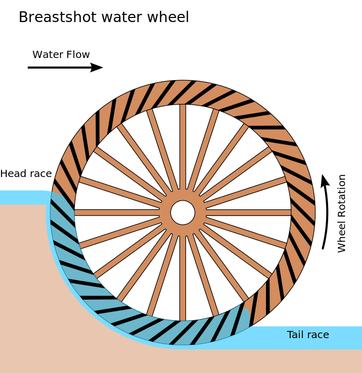
The Breastshot Water Wheel Design is another vertically-mounted waterwheel design where the water enters the buckets about half way up at axle height, or just above it, and then flows out at the bottom in the direction of the wheels rotation. Generally, the breastshot waterwheel is used in situations were the head of water is insufficient to power an overshot or pitchback waterwheel design from above.
The disadvantage here is that the gravitational weight of the water is only used for about one quarter of the rotation unlike previously which was for half the rotation. To overcome this low head height, the waterwheels buckets are made wider to extract the required amount of potential energy from the water.
Breastshot waterwheels use about the same gravitational weight of the water to rotate the wheel but as the head height of the water is around half that of a typical overshot waterwheel, the buckets are a lot wider than previous waterwheel designs to increase the volume of the water caught in the buckets.
The disadvantage of this type of design is an increase in the width and weight of the water being carried by each bucket. As with the pitchback design, the breastshot wheel uses the energy of the water twice as the waterwheel is designed to sit in the water allowing the waste water to help in the rotation of the wheel as it flows away down stream.
Historically water wheels have been used for milling flour, cereals and other such mechanical tasks. But water wheels can also be used for the generation of electricity, called a Hydro Power system.
By connecting an electrical generator to the waterwheels rotating shaft, either directly or indirectly using drive belts and pulleys, waterwheels can be used to generate power continuously 24 hours a day unlike solar energy. If the waterwheel is designed correctly, a small or “micro” hydroelectric system can produce enough electricity to power lighting and/or electrical appliances in an average home.
Look for Water wheel Generators designed to produce its optimum output at relatively low speeds. For small projects, a small DC motor can be used as a low-speed generator or an automotive alternator but these are designed to work at much higher speeds so some form of gearing may be required. A wind turbine generator makes an ideal waterwheel generator as it is designed for low speed, high output operation.
If there is a fairly fast flowing river or stream near to your home or garden which you can use, then a small scale hydro power system may be a better alternative to other forms of renewable energy sources such as “Wind Energy” or “Solar Energy” as it has a lot less visual impact. Also just like wind and solar energy, with a grid-connected small scale waterwheel designed generating system connected to the local utility grid, any electricity you generate but don’t use can be sold back to the electricity company.
In the next tutorial about Hydro Energy, we will look at the different types of turbines available which we could attach to our waterwheel design for hydro power generation. For more information about Waterwheel Design and how to generate your own electricity using the power of water, or obtain more hydro energy information about the various waterwheel designs available, or to explore the advantages and disadvantages of hydro energy, then Click Here to order your copy from Amazon today about the principles and construction of waterwheels which can be used for generating electricity.

A waterwheel is a type of device that takes advantage of flowing or falling water to generate power by using a set of paddles mounted around a wheel. The falling force of the water pushes the paddles, rotating a wheel. This rotation of a wheel can be transmitted to a variety of machines through a shaft at the center of the wheel.metal with many blades or buckets along the edge of the wheel to capture the power of the moving water.
Waterwheels are usually positioned vertically over a water source. This means that the axle is positioned horizontally. This axle transfers the energy from the falling water to a drive belt or a system of gears that then operates some sort of machine. These wheels require some source of falling or flowing water, and these sources can include streams or rivers. Sometimes special ponds known as mill ponds were created by damming a flowing stream. This creates a special channel known as a
Although waterwheels are not used widely today, hydroelectric dams function on the same basic principle of using the power of flowing water to move machines known as turbines.
Overshot wheels are a type of waterwheel that can be built if there is a significant height drop in the river or body of water being used to move the wheel. Generally, these are built on the side of a hill as a drop of at least 4.5 meters.
In this type of waterwheel, the water exits the flume above the wheel itself. The water then falls down onto the blades of the waterwheel, pushing the wheel forward. The fact that water is introduced at the very top of the wheel means that the water falls the greatest distance, making the wheel highly efficient - from 80-90%.
In areas that have little to no slope, undershot waterwheels are the only type of waterwheel that will work. Since there is almost no drop in the water, these wheels are inefficient compared to other types. This is because the waterwheel relies on there being large quantities of water moving quickly to move the wheel. Because of this, the wheels tend to be built on large, strong rivers.
In this type of waterwheel, there is no flume. Instead the water rushes along the bottom of the waterwheel, spinning it backwards compared to the water flow. This spinning motion occurs because the water pushes along the blades that are in contact with the surface of the water.
Breastshot wheels are used where there is a moderate drop in the height of the water. Generally, breastshot wheels are used if there is a drop between 1.8 to 2.4 meters.iron. These wheels can be made to be very large to increase their power output.
In this type of waterwheel, water flows onto the wheel about half way up and pushes the blades of the wheel downwards as it falls. The water then continues to flow underneath the wheel, pushing it more as it flows forward.
Students learn the history of the waterwheel and common uses for water turbines today. They explore kinetic energy by creating their own experimental waterwheel from a two-liter plastic bottle. They investigate the transformations of energy involved in turning the blades of a hydro-turbine into work, and experiment with how weight affects the rotational rate of the waterwheel. Students also discuss and explore the characteristics of hydroelectric plants.
Throughout human history, waterwheels performed many types of mechanical work: saw timber, drive pumps, run farm equipment, trip hammers, grind grains into flour, make iron products and power textile mills. Today, the modern equivalents of waterwheels are the huge turbines of hydroelectric power plants, which generate electricity that we use everyday to perform all types of work: heating, cooling, refrigeration, and the powering of appliances, televisions and entertainment. Hydropower is a way to produce electricity using a renewable energy source that does not use fossil fuels, pollute or produce greenhouse gases. Yet, such big projects require engineers to consider all the implications of their impact on the surrounding environment.
Students learn how water is used to generate electricity. They investigate water"s potential-to-kinetic energy transformation in hands-on activities about falling water and waterwheels. During the activities, they take measurements, calculate averages and graph results.
Students observe a model waterwheel to investigate the transformations of energy involved in turning the blades of a hydro-turbine. They work as engineers to create model waterwheels while considering resources such as time and materials, in their designs. Students also discuss and explore the chara...
Students learn how engineers design devices that use water to generate electricity by building model water turbines and measuring the resulting current produced in a motor. Student teams work through the engineering design process to build the turbines, analyze the performance of their turbines and ...
Today we are going to talk about hydropower. Hydropower is a renewable energyresource. Hydro means water, so hydropower is something that gets power from water. Hydropower captures energyfrom the movement of water or water"s kinetic energy. Have you ever seen a waterwheel? A waterwheel is an example of how people have created a machine that uses and produces hydropower. A waterwheel is also called a turbine.
The waterwheelis one of the oldest known sources of power. A waterwheel spins as a stream of water (which is being pulled down by gravity) hits its paddles or blades. The first reference to its use is about 4000 BC. More than 2,000 years ago, farmers used waterwheels to grind wheat into flour. The gears of the wheel ground the wheat into flour. Waterwheels use the kinetic energy of moving water to perform many types of mechanical work. Waterwheels were used to power farm equipment, drive pumps, trip hammers, saw timber, grind grains into flour, forge iron, and power textile mills. Before the development of steam power during the colonial and industrial revolution eras, waterwheels were the only sources of power (besides human or animal power). Often, towns were built close to a river so waterwheels could be built nearby
Three types of waterwheels are tha horizontal waterwheel, overshot vertical waterwheel, and undershot vertical waterwheel. In the horizontal waterwheel, water flows from an aqueduct or pipe from the side of the wheel and onto the wheel. The forward motion of the water turns the wheel. In the overshot vertical waterwheel, water drops down from a water source above onto the wheel, turning it. Undershot vertical waterwheels are large vertical waterwheels placed in a stream such that the wheel is turned by the moving water.
The world"s first hydroelectric power plant began operating in 1882, on the Fox River in Appleton, WI. Hydroelectricis when water is changed into electrical energy. Hydroelectricity can be used to power lights, heaters, appliances and televisions. The plant was started by a man who was a paper manufacturer and engineer, and was inspired by Thomas Edison"s plans for an electric power plant.
Today, engineers around the world develop hydroelectric plants to meet growing energy demand. The waterwheel concept is used in dams to generate electricity. Damsare some of the largest human-made structures on Earth. In fact, the Hoover Dam on the Colorado River in Nevada is 221 meters high, 379 meters long and 14 meters wide at the top. That is pretty big! It has 17 electric generators and provides electricity for about 500,000 homes in Nevada, Arizona and California. The world"s largest hydroelectric power plant—the Itaipú Power Plant on the Paraná River in Brazil—provides energy to two countries (25% of Brazil"s electricity and 78% of Paraguay"s electricity).
The same concepts that are employed in a waterwheel are used in these gigantic hydroelectric power plants. A waterwheel is a simple turbine—a device with buckets, paddles or blades that is rotated by moving water, converting the kinetic energy of water into mechanical movement. Hydroelectric power plants use huge and more complex turbines to generate electricity.
In this activity, we are going to designa modelof an overshot vertical waterwheel. Engineers often build models or prototypesof a waterwheel or any product or large project before they build the real thing. This method of testing something on a small scale helps to prevent mistakes in making the real ones work.
With a pen or marker, draw 6 to 8 lengthwise equidistant lines along the length of the large plastic bottle. These mark the locations where index card "water catchers" will be taped.
Fold the index cards to make small boxes or envelopes ("catchers") with open sides. These will serve as waterwheel paddles (or buckets or blades) to catch the water. Exactly how the index cards are folded and attached provides an engineering design opportunity for each team.
Mark one index card with an "X" so counting the number of turns is easier. (The students will count each time the marked catcher reaches the top of the waterwheel while turning.)
Tape the index card "catchers" to the soda bottle at each line. Your waterwheel will spin in one specific direction (choose either clockwise or counterclockwise), so make sure each catcher faces the same direction to help the bottle to spin in that direction. See Figure 2.
Discuss how to measure the rate of rotation of the waterwheel (refer to the Waterwheel Worksheet). Agree on what it means for the waterwheel to slow down. Does it have to completely stop? Have the students create a procedure to count the turns of the waterwheel during a given period of time. For example, during the pouring, as the waterwheel spins, students could count the number of turns by noting how many times the marked catcher passes the top of the wheel.
(Conduct this step over a sink or outside.) Have one team member keep track of the elapsed time using the second hand on a clock or watch. As soon as the wheel is spinning, start taking the time while other team members count the number of turns the waterwheel makes. Stop counting turns and keeping track of the time when the waterwheel slows down.
Change roles and repeat until every member has counted or there is a consistent measurement for the rate at which the waterwheel spins. Record your data on the worksheet. Have students complete the front side of the worksheet.
Have teams fasten a string to the neck of their water turbines. Tie objects to the string so the spinning waterwheel pulls them up as the string rolls up around the neck of the bottle.
(Conduct this step over a sink or outside. See Figure 3.) Have one team member keep track of the elapsed time using the second hand on a clock or watch. As soon as the waterwheel (with the weight) is spinning, start taking the time while other team members count the number of turns the waterwheel makes. Stop counting turns and keeping track of the time when the waterwheel slows down. Repeat this until every member has counted or there is a consistent measurement for the rate at which the waterwheel spins. Record your data on the worksheet. Have students complete the back side of the worksheet.
potential energy: Potential energy is the energy stored by an object as a result of its position. For example, a roller coaster at the top of a hill, or water being held behind a dam.
waterwheel: A wheel that rotates by direct action of water; used to generate power or do work. The wheel often includes buckets, paddles or blades to catch the water. A simple turbine.
True or False: Hydropower dams do not interfere with natural wildlife. (Answer: False. Dams can disrupt migratory fish patterns and spawning habits, especially for species like salmon. This can have devastating effects on both the fish population and people whose livelihoods depend on these fish. Change in water levels can also fatally affect other wildlife and plants.)
Question/Answer:Ask the students how waterwheels (hydromills) and windmills are similar (Answer: Both have "vanes" and a turbine shaft, and both generate renewable energy.)
How would engineers use this understanding to design hydroelectric power plants? (Answer: Engineers would learn about the different paddle or blade designs to see how well they moved the weight. The better the blade design, the faster the waterwheel turned and moved the weight upwards. They would use this information to design a turbine that generated the most electricity from the turning wheel.)
Engineering Design Project: Divide the class into groups and inform them that they are engineering teams working for H2O Solutions, an engineering design company that specializes in waterwheels and water energy. The city has asked them to use what they have learned in this activity to design a waterwheel that is more efficient than the waterwheel they just designed during this activity. Tell the teams that they can include whatever resources (e.g., time, materials) that they want in their design. Ask them to sketch their new design. Have teams present their designs to the rest of the class.
To use the natural water flows in a river or stream for hydropower, what type of natural river conditions do engineers require? (Answer: It must be fast-moving water.)
What are some reasons why engineers construct hydroelectric power plants? (Possible answers: To produce electricity. To make use of a renewable energy source [water]. To produce electricity without polluting or producing greenhouse gases.)
Why do engineers construct dams for large hydroelectric power systems? (Answer: The dam holds a great deal of water in one place to supply the kinetic energy required to turn the turbine blades.)
How was the waterwheel you made similar to what happens in a hydroelectric power plant? (Answer: Water dropped from a container to spin the blades just like water runs from a dam to spin the blades of a turbine. The spinning waterwheel was used to do work just like the spinning blades of turbines make electricity, which we use to do work.)
Re-Design Practice:Have the students list on their worksheet any design or fabrication changes they would make to their waterwheel to make it work better.
Have students make waterwheels out of different types of materials or bottles. How does the material of the waterwheel affect the amount of work that is done? Make available bottles with different shapes and volume/capacities. Ask each team to come to the sink where the tap water is running at a constant flow rate for each. Finally, ask the students to compare their waterwheels to their peers" based on the number of turns per minute at the same flow rate of water. Ask the students why their waterwheel performs differently than the others". Which type works best? Why?
How does the size of the index card affect the efficiency of the waterwheel? Have the students measure the length and width of the index card, and find its area. After the sides of the index card have been bent to create the box-shaped "catchers," have the students calculate the volume of water that the catcher can hold. What folding method allows for the largest amount of water to be held in the catcher? Is it better to have a waterwheel catcher that can hold a lot of water or a little bit of water? Compare results as a class to find out what shapes and sizes work best!
Make some other water turbine models. See Make a Turbine Science Project at Energy Quest, at http://www.energyquest.ca.gov/projects/turbine.html and Hydro-Power Science Project at Energy Quest, at http://www.energyquest.ca.gov/projects/hydro-power.html .
Have students conduct research: How much water to do we use daily? For what purposes? Do people in other countries use as much water? What are some ways to conserve water and energy?
Have students research the history of several large dams and hydroelectric power plants, such as Aswan High Dam, Three Gorges Dam, Itaipú Dam, Guri Dam, Hoover Dam, Dalles Dam and Grand Coulee Dam. How old are they? How much electric power do they produce? How much water does each dam hold? What were the environmental concerns about building them?
For more advanced students, have them evaluate the waterwheel as an energy source. They could measure the amount of water required to turn the waterwheel a certain number of turns with a gram load. Place a large bucket under the waterwheel to capture the water. See how many turns it takes to lift an object a given distance by turning the string around the bottle of the neck. Finally, compare this idea to real energy costs. (The percent efficiency can be calculated by dividing the weight of the object by the weight of the water required to raise the object the same distance the water fell — about one foot — then multiply the result by 100.)
For more advanced students, have them explore different waterwheel variables, such as the type, shape and material of the turbine, number and position of fins on the turbine, etc.
Moving Water - Moving Blades: An Overshot Waterwheel. Hydro-Power Science Projects, Experiment with Water to Produce Energy, California Energy Commission. Accessed October 27, 2005 www.energyquest.ca.gov/projects/waterenergy.html
Water Power. Lowell National Historical Park & Tsongas Industrial History Center, National Park Service. Accessed October 27, 2005. (Good graphics of waterwheel mechanics) www.nps.gov

To establish if your site is suitable for generating electricity from a Poncelet Wheel you need to have flowing water and you need to know the three key components, which are WATER VELOCITY (in metres per second), AREA (in square metres) and HEAD (in metres).
The more flowing water you have, the more potential power you can generate. The Water Velocity can be estimated by recording how long (in seconds) a "floating object" (such as a ball) takes to travel over a given distance (in metres). Divide the distance by the time taken and you will have the Water Velocity (in metres per second).
Most turbines work on an efficiency of up to 70% (greater efficiencies can be obtained from our Archimedes Screw) using this efficiency value (i.e. 0.7) would give you the expected output from the site.

With over 10 years experience, we specialise in producing water wheels and Archimedes Screws, using our extensive knowledge and expertise of the traditional Overshot, Breastshot, Poncelet and Zuppinger water wheels.
The wheel can be used as a typical overshot wheel if the upstream water level (head) exceeds the diameter of the wheel, with lower head levels it can be used as a pitch back wheel, the head range is 2.5m down to 1.5m.
The wheel can be supplied in kit form for the customer to assemble, possibly on site, or fully assembled. The gearbox, generator and control system will be specified but can be sourced by the customer. This is a fish friendly application for generating electricity.
The size of the standard wheel is 2m diameter x 0.9m width, optimum flow is around 0.2m3/s. This gives a power range between 3kW and 1.7kW depending on the water head and flow that is available at the instalation.

Water is an amazing resource! We all know that we need to drink water to survive, but did you know that humans have been using the power of water to do work or generate electricity for thousands of years?
The Roman Empire used the power of water extensively in the first century BCE (before common era). It is known that the Greeks used water wheels to grind flour more than 2,000 years ago. There is evidence that water wheels were also used in China, and the French are responsible for creating one of the first hydropower turbines in the mid-1700s.
Water wheels are machines that use the energy of flowing or falling water (or both) to turn a wheel. The axle of the turning wheel can then power other machines to do work.
Water wheels were used throughout Europe during the Middle Ages (approximately 500 to 1500), as the main source of power for driving large machines. Some examples of how water wheels were used are:
To produce power, the energy of flowing water pushes against the paddles or buckets and turns the wheel. This causes the axle to turn which drives belts and gears that power the machinery. The larger the diameter of the wheel, the greater ‘leverage’ and so the greater turning effect on the axle that drives the machine. The mill race has two parts: the part that brings the water to the wheel is called the ‘head race’ and the part that carries the water away is the ‘tail race’.
Water wheels can be horizontal or vertical, but the vertical design is more common and much more efficient. There are two common vertical water wheel designs: ‘undershot’ and ‘overshot’.
An undershot wheel is mounted above the mill race with the bottom of the wheel in the water. The flowing water strikes the paddles or blades and turns the wheel. The faster the water is flowing the faster the wheel will turn.
In an overshot water wheel, the mill race brings the water to the top of the wheel, where it strikes the paddles or buckets and turns the wheel. This is more efficient because as well as the force of the flowing water, the weight of the falling water helps to turn the wheel. This is a benefit of this design as it will still work even when the flow of water is not very fast.
The Beaconsfield Gold and Heritage Museum (Grubb Shaft) in Tasmania has a working overshot water wheel that drives a huge stamping-battery machine that was used to crush the quartz ore containing gold. The machine was built in 1862 and still works!
Another fine Australian example is the Bridgewater Mill in South Australia built by John Dunn in 1859. This was originally a flour mill and is still preserved today as a restaurant and tourist destination. This is an example of a ‘backshot wheel’, a version of the overshot water wheel where the water from the race is introduced just behind the top of the wheel.
In recent times, the principles of hydropower have been revived through water-powered turbines which use the energy of water flowing down a slope to generate hydroelectricity.
Hydroelectric dam systems generate power when the water that has been stored in the dam is released into a pipeline and flows over a turbine. The force of the water causes the turbine to spin, which operates a generator. The generator produces electricity which is transferred to a substation and then into a grid. Excess water is released back into a waterway.
At first, the Scheme was going to be for irrigation, but the designers knew it had potential to generate electricity too. The government was able to pay for this huge structure through the money it earnt from selling the electricity. The Scheme diverts water from the Snowy, Eucumbene and Murrumbidgee rivers westward through the Great Dividing Range and then releases water into the Murray and Murrumbidgee rivers.
Wave power is still quite new in Australia, but research has shown that our southern coastline could be a great resource as it has deep water with consistently large waves.
To generate power, large ‘floats’ are tied to the ocean floor. The motion of the waves causes the floats to move up and down which powers a pump. The pump moves pressurised water along pipes to the land where there is a turbine which runs a generator. The generator produces electricity.

A water wheel is a machine for converting the energy of flowing or falling water into useful forms of power, often in a watermill. A water wheel consists of a wheel (usually constructed from wood or metal), with a number of blades or buckets arranged on the outside rim forming the driving car. Water wheels were still in commercial use well into the 20th century but they are no longer in common use. Uses included milling flour in gristmills, grinding wood into pulp for papermaking, hammering wrought iron, machining, ore crushing and pounding fibre for use in the manufacture of cloth.
Some water wheels are fed by water from a mill pond, which is formed when a flowing stream is dammed. A channel for the water flowing to or from a water wheel is called a mill race. The race bringing water from the mill pond to the water wheel is a headrace; the one carrying water after it has left the wheel is commonly referred to as a tailrace.
Waterwheels were used for various purposes from agriculture to metallurgy in ancient civilizations spanning the Hellenistic Greek world, Rome, China and India. Waterwheels saw continued use in the Post-classical age, like the Middle Ages of Europe and the Islamic Golden Age, but also elsewhere. In the mid to late 18th century John Smeaton"s scientific investigation of the water wheel led to significant increases in efficiency supplying much needed power for the Industrial Revolution.turbine, developed by Benoît Fourneyron, beginning with his first model in 1827.elevations, that exceed the capability of practical-sized waterwheels.
The main difficulty of water wheels is their dependence on flowing water, which limits where they can be located. Modern hydroelectric dams can be viewed as the descendants of the water wheel, as they too take advantage of the movement of water downhill.
Overshot and backshot water wheels are typically used where the available height difference is more than a couple of meters. Breastshot wheels are more suited to large flows with a moderate head. Undershot and stream wheel use large flows at little or no head.
There is often an associated millpond, a reservoir for storing water and hence energy until it is needed. Larger heads store more gravitational potential energy for the same amount of water so the reservoirs for overshot and backshot wheels tend to be smaller than for breast shot wheels.
Overshot and pitchback water wheels are suitable where there is a small stream with a height difference of more than 2 metres (6.5 ft), often in association with a small reservoir. Breastshot and undershot wheels can be used on rivers or high volume flows with large reservoirs.
Stream wheels are cheaper and simpler to build and have less of an environmental impact, than other types of wheels. They do not constitute a major change of the river. Their disadvantages are their low efficiency, which means that they generate less power and can only be used where the flow rate is sufficient. A typical flat board undershot wheel uses about 20 percent of the energy in the flow of water striking the wheel as measured by English civil engineer John Smeaton in the 18th century.
Stream wheels mounted on floating platforms are often referred to as hip wheels and the mill as a ship mill. They were sometimes mounted immediately downstream from bridges where the flow restriction of the bridge piers increased the speed of the current.
An undershot wheel is a vertically mounted water wheel with a horizontal axle that is rotated by the water from a low weir striking the wheel in the bottom quarter. Most of the energy gain is from the movement of the water and comparatively little from the head. They are similar in operation and design to stream wheels.
The word breastshot is used in a variety of ways. Some authors restrict the term to wheels where the water enters at about the 10 o’clock position, others 9 o’clock, and others for a range of heights.
The small clearance between the wheel and the masonry requires that a breastshot wheel has a good trash rack ("screen" in British English) to prevent debris from jamming between the wheel and the apron and potentially causing serious damage.
Breastshot wheels are less efficient than overshot and backshot wheels but they can handle high flow rates and consequently high power. They are preferred for steady, high-volume flows such as are found on the Fall Line of the North American East Coast. Breastshot wheels are the most common type in the United States of America
A vertically mounted water wheel that is rotated by water entering buckets just past the top of the wheel is said to be overshot. The term is sometimes, erroneously, applied to backshot wheels, where the water goes down behind the wheel.
A typical overshot wheel has the water channeled to the wheel at the top and slightly beyond the axle. The water collects in the buckets on that side of the wheel, making it heavier than the other "empty" side. The weight turns the wheel, and the water flows out into the tail-water when the wheel rotates enough to invert the buckets. The overshot design is very efficient, it can achieve 90%,
Nearly all of the energy is gained from the weight of water lowered to the tailrace although a small contribution may be made by the kinetic energy of the water entering the wheel. They are suited to larger heads than the other type of wheel so they are ideally suited to hilly countries. However even the largest water wheel, the Laxey Wheel in the Isle of Man, only utilises a head of around 30 m (100 ft). The world"s largest head turbines, Bieudron Hydroelectric Power Station in Switzerland, utilise about 1,869 m (6,132 ft).
Overshot wheels require a large head compared to other types of wheel which usually means significant investment in constructing the headrace. Sometimes the final approach of the water to the wheel is along a flume or penstock, which can be lengthy.
A backshot wheel (also called pitchback) is a variety of overshot wheel where the water is introduced just before the summit of the wheel. In many situations, it has the advantage that the bottom of the wheel is moving in the same direction as the water in the tailrace which makes it more efficient. It also performs better than an overshot wheel in flood conditions when the water level may submerge the bottom of the wheel. It will continue to rotate until the water in the wheel pit rises quite high on the wheel. This makes the technique particularly suitable for streams that experience significant variations in flow and reduces the size, complexity, and hence cost of the tailrace.
The direction of rotation of a backshot wheel is the same as that of a breastshot wheel but in other respects, it is very similar to the overshot wheel. See below.
Some wheels are overshot at the top and backshot at the bottom thereby potentially combining the best features of both types. The photograph shows an example at Finch Foundry in Devon, UK. The head race is the overhead timber structure and a branch to the left supplies water to the wheel. The water exits from under the wheel back into the stream.
A special type of overshot/backshot wheel is the reversible water wheel. This has two sets of blades or buckets running in opposite directions so that it can turn in either direction depending on which side the water is directed. Reversible wheels were used in the mining industry in order to power various means of ore conveyance. By changing the direction of the wheel, barrels or baskets of ore could be lifted up or lowered down a shaft or inclined plane. There was usually a cable drum or a chain basket on the axle of the wheel. It is essential that the wheel have braking equipment to be able to stop the wheel (known as a braking wheel). The oldest known drawing of a reversible water wheel was by Georgius Agricola and dates to 1556.
The earliest waterwheel working like a lever was described by Zhuangzi in the late Warring States period (476-221 BC). It says that the waterwheel was invented by Zigong, a disciple of Confucius in the 5th century BC.Chinese of the Eastern Han Dynasty were using water wheels to crush grain in mills and to power the piston-bellows in forging iron ore into cast iron.
In the text known as the Xin Lun written by Huan Tan about 20 AD (during the usurpation of Wang Mang), it states that the legendary mythological king known as Fu Xi was the one responsible for the pestle and mortar, which evolved into the tilt-hammer and then trip hammer device (see trip hammer). Although the author speaks of the mythological Fu Xi, a passage of his writing gives hint that the water wheel was in widespread use by the 1st century AD in China (Wade-Giles spelling):
Fu Hsi invented the pestle and mortar, which is so useful, and later on it was cleverly improved in such a way that the whole weight of the body could be used for treading on the tilt-hammer (tui), thus increasing the efficiency ten times. Afterwards the power of animals—donkeys, mules, oxen, and horses—was applied by means of machinery, and water-power too used for pounding, so that the benefit was increased a hundredfold.
In the year 31 AD, the engineer and Prefect of Nanyang, Du Shi (d. 38), applied a complex use of the water wheel and machinery to power the bellows of the blast furnace to create cast iron. Du Shi is mentioned briefly in the Hou Han Shu) as follows (in Wade-Giles spelling):
In the seventh year of the Chien-Wu reign period (31 AD) Tu Shih was posted to be Prefect of Nanyang. He was a generous man and his policies were peaceful; he destroyed evil-doers and established the dignity (of his office). Good at planning, he loved the common people and wished to save their labor. He invented a water-power reciprocator (shui phai) for the casting of (iron) agricultural implements. Those who smelted and cast already had the push-bellows to blow up their charcoal fires, and now they were instructed to use the rushing of the water (chi shui) to operate it ... Thus the people got great benefit for little labor. They found the "water(-powered) bellows" convenient and adopted it widely.
Water wheels in China found practical uses such as this, as well as extraordinary use. The Chinese inventor Zhang Heng (78–139) was the first in history to apply motive power in rotating the astronomical instrument of an armillary sphere, by use of a water wheel.mechanical engineer Ma Jun (c. 200–265) from Cao Wei once used a water wheel to power and operate a large mechanical puppet theater for the Emperor Ming of Wei (r. 226–239).
The ancient Greeks invented the waterwheel independently and used it in nearly all of the forms and functions described above, including its application for watermilling.Hellenistic period between the 3rd and 1st century BC.
The compartmented water wheel comes in two basic forms, the wheel with compartmented body (Latin tympanum) and the wheel with compartmented rim or a rim with separate, attached containers.sakia gear.
The earliest literary reference to a water-driven, compartmented wheel appears in the technical treatise Pneumatica (chap. 61) of the Greek engineer Philo of Byzantium (ca. 280−220 BC).Parasceuastica (91.43−44), Philo advises the use of such wheels for submerging siege mines as a defensive measure against enemy sapping.dry docks in Alexandria under the reign of Ptolemy IV (221−205 BC).papyri of the 3rd to 2nd century BC mention the use of these wheels, but don"t give further details.Ancient Near East before Alexander"s conquest can be deduced from its pronounced absence from the otherwise rich oriental iconography on irrigation practices.
The earliest depiction of a compartmented wheel is from a tomb painting in Ptolemaic Egypt which dates to the 2nd century BC. It shows a pair of yoked oxen driving the wheel via a sakia gear, which is here for the first time attested, too.Museum of Alexandria, at the time the most active Greek research center, may have been involved in its invention.Alexandrian War in 48 BC tells of how Caesar"s enemies employed geared waterwheels to pour sea water from elevated places on the position of the trapped Romans.
Around 300 AD, the noria was finally introduced when the wooden compartments were replaced with inexpensive ceramic pots that were tied to the outside of an open-framed wheel.
The Romans used waterwheels extensively in mining projects, with enormous Roman-era waterwheels found in places like modern-day Spain. They were reverse overshot water-wheels designed for dewatering deep underground mines.Vitruvius, including the reverse overshot water-wheel and the Archimedean screw. Many were found during modern mining at the copper mines at Rio Tinto in Spain, one system involving 16 such wheels stacked above one another so as to lift water about 80 feet from the mine sump. Part of such a wheel was found at Dolaucothi, a Roman gold mine in south Wales in the 1930s when the mine was briefly re-opened. It was found about 160 feet below the surface, so must have been part of a similar sequence as that discovered at Rio Tinto. It has recently been carbon dated to about 90 AD, and since the wood from which it was made is much older than the deep mine, it is likely that the deep workings were in operation perhaps 30–50 years after. It is clear from these examples of drainage wheels found in sealed underground galleries in widely separated locations that building water wheels was well within their capabilities, and such verticals water wheels commonly used for industrial purposes.
Taking indirect evidence into account from the work of the Greek technician Apollonius of Perge, the British historian of technology M.J.T. Lewis dates the appearance of the vertical-axle watermill to the early 3rd century BC, and the horizontal-axle watermill to around 240 BC, with Byzantium and Alexandria as the assigned places of invention.Strabon (ca. 64 BC–AD 24) to have existed sometime before 71 BC in the palace of the Pontian king Mithradates VI Eupator, but its exact construction cannot be gleaned from the text (XII, 3, 30 C 556).
The first clear description of a geared watermill offers the late 1st century BC Roman architect Vitruvius who tells of the sakia gearing system as being applied to a watermill.
About the same time, the overshot wheel appears for the first time in a poem by Antipater of Thessalonica, which praises it as a labour-saving device (IX, 418.4–6).Lucretius (ca. 99–55 BC) who likens the rotation of the waterwheel to the motion of the stars on the firmament (V 516).central Gaul.Barbegal watermill complex a series of sixteen overshot wheels was fed by an artificial aqueduct, a proto-industrial grain factory which has been referred to as "the greatest known concentration of mechanical power in the ancient world".
In Roman North Africa, several installations from around 300 AD were found where vertical-axle waterwheels fitted with angled blades were installed at the bottom of a water-filled, circular shaft. The water from the mill-race which entered tangentially the pit created a swirling water column that made the fully submerged wheel act like true water turbines, the earliest known to date.
Apart from its use in milling and water-raising, ancient engineers applied the paddled waterwheel for automatons and in navigation. Vitruvius (X 9.5–7) describes multi-geared paddle wheels working as a ship odometer, the earliest of its kind. The first mention of paddle wheels as a means of propulsion comes from the 4th–5th century military treatise
Ancient water-wheel technology continued unabated in the early medieval period where the appearance of new documentary genres such as legal codes, monastic charters, but also hagiography was accompanied with a sharp increase in references to watermills and wheels.
The earliest excavated water wheel driven by tidal power was the Nendrum Monastery mill in Northern Ireland which has been dated to 787, although a possible earlier mill dates to 619. Tide mills became common in estuaries with a good tidal range in both Europe and America generally using undershot wheels.
Cistercian monasteries, in particular, made extensive use of water wheels to power watermills of many kinds. An early example of a very large water wheel is the still extant wheel at the early 13th century Real Monasterio de Nuestra Senora de Rueda, a Cistercian monastery in the Aragon region of Spain. Grist mills (for corn) were undoubtedly the most common, but there were also sawmills, fulling mills and mills to fulfil many other labour-intensive tasks. The water wheel remained competitive with the steam engine well into the Industrial Revolution. At around the 8th to 10th century, a number of irrigation technologies were brought into Spain and thus introduced to Europe. One of those technologies is the Noria, which is basically a wheel fitted with buckets on the peripherals for lifting water. It is similar to the undershot water wheel mentioned later in this article. It allowed peasants to power watermills more efficiently. According to Thomas Glick"s book, Irrigation and Society in Medieval Valencia, the Noria probably originated from somewhere in Persia. It has been used for centuries before the technology was brought into Spain by Arabs who had adopted it from the Romans. Thus the distribution of the Noria in the Iberian peninsula "conforms to the area of stabilized Islamic settlement".Spaniards, the technology spread to the New World in Mexico and South America following Spanish expansion
The type of water wheel selected was dependent upon the location. Generally if only small volumes of water and high waterfalls were available a millwright would choose to use an overshot wheel. The decision was influenced by the fact that the buckets could catch and use even a small volume of water.
Harnessing water-power enabled gains in agricultural productivity, food surpluses and the large scale urbanization starting in the 11th century. The usefulness of water power motivated European experiments with other power sources, such as wind and tidal mills.canals, put Europe on a hydraulically focused path, for instance water supply and irrigation technology was combined to modify supply power of the wheel.feudal state.
The water mill was used for grinding grain, producing flour for bread, malt for beer, or coarse meal for porridge.fulling mill, which was used for cloth making. The trip hammer was also used for making wrought iron and for working iron into useful shapes, an activity that was otherwise labour-intensive. The water wheel was also used in papermaking, beating material to a pulp. In the 13th century water mills used for hammering throughout Europe improved the productivity of early steel manufacturing. Along with the mastery of gunpowder, waterpower provided European countries worldwide military leadership from the 15th century.
Millwrights distinguished between the two forces, impulse and weight, at work in water wheels long before 18th-century Europe. Fitzherbert, a 16th-century agricultural writer, wrote "druieth the wheel as well as with the weight of the water as with strengthe [impulse]".Leonardo da Vinci also discussed water power, noting "the blow [of the water] is not weight, but excites a power of weight, almost equal to its own power".laws of force. Evangelista Torricelli"s work on water wheels used an analysis of Galileo"s work on falling bodies, that the velocity of a water sprouting from an orifice under its head was exactly equivalent to the velocity a drop of water acquired in falling freely from the same height.
The water wheel was a driving force behind the earliest stages of industrialization in Britain. Water-powered reciprocating devices were used in trip hammers and blast furnace bellows. Richard Arkwright"s water frame was powered by a water wheel.
The most powerful water wheel built in the United Kingdom was the 100 hp Quarry Bank Mill water wheel near Manchester. A high breastshot design, it was retired in 1904 and replaced with several turbines. It has now been restored and is a museum open to the public.
The biggest working water wheel in mainland Britain has a diameter of 15.4 m (51 ft) and was built by the De Winton company of Caernarfon. It is located within the Dinorwic workshops of the National Slate Museum in Llanberis, North Wales.
The largest working water wheel in the world is the Laxey Wheel (also known as Lady Isabella) in the village of Laxey, Isle of Man. It is 72 feet 6 inches (22.10 m) in diameter and 6 feet (1.83 m) wide and is maintained by Manx National Heritage.
During the Industrial Revolution, in the first half of the 19th century engineers started to design better wheels. In 1823 Jean-Victor Poncelet invented a very efficient undershot wheel design that could work on very low heads, which was commercialized and became popular by late 1830s. Other designs, as the Sagebien wheel, followed later. At the same time Claude Burdin was working on a radically different machine which he called turbine, and his pupil Benoît Fourneyron designed the first commercial one in the 1830s.
Development of water turbines led to decreased popularity of water wheels. The main advantage of turbines is that its ability to harness head is much greater than the diameter of the turbine, whereas a water wheel cannot effectively harness head greater than its diameter. The migration from water wheels to modern turbines took about one hundred years.
Water wheels were used to power sawmills, grist mills and for other purposes during development of the United States. The 40 feet (12 m) diameter water wheel at McCoy, Colorado, built in 1922, is a surviving one out of many which lifted water for irrigation out of the Colorado River.
Two early improvements were suspension wheels and rim gearing. Suspension wheels are constructed in the same manner as a bicycle wheel, the rim being supported under tension from the hub- this led to larger lighter wheels than the former design where the heavy spokes were under compression. Rim-gearing entailed adding a notched wheel to the rim or shroud of the wheel. A stub gear engaged the rim-gear and took the power into the mill using an independent line shaft. This removed the rotative stress from the axle which could thus be lighter, and also allowed more flexibility in the location of the power train. The shaft rotation was geared up from that of the wheel which led to less power loss. An example of this design pioneered by Thomas Hewes and refined by William Armstrong Fairburn can be seen at the 1849 restored wheel at the Portland Basin Canal Warehouse.
Australia has a relatively dry climate, nonetheless, where suitable water resources were available, water wheels were constructed in 19th-century Australia. These were used to power sawmills, flour mills, and stamper batteries used to crush gold-bearing ore. Notable examples of water wheels used in gold recovery operations were the large Garfield water wheel near Chewton—one of at least seven water wheels in the surrounding area—and the two water wheels at Adelong Falls; some remnants exist at both sites.Walhalla once had at least two water wheels, one of which was rolled to its site from Port Albert, on its rim using a novel trolley arrangement, taking nearly 90 days.water wheel at Jindabyne, constructed in 1847, was the first machine used to extract energy—for flour milling—from the Snowy River.
The early history of the watermill in India is obscure. Ancient Indian texts dating back to the 4th century BC refer to the term cakkavattaka (turning wheel), which commentaries explain as arahatta-ghati-yanta (machine with wheel-pots attached). On this basis, Joseph Needham suggested that the machine was a noria. Terry S. Reynolds, however, argues that the "te


 8613371530291