
overshot water wheel generator pricelist

The overshot wheel is the most common wheel seen in North America. It is a gravity wheel. This means that it harnesses the force of gravity acting vertically on the water as it travels from the top to the bottom of the wheel. Properly designed for a particular site, and correctly timed, an overshot The overshot wheel is most effective when it turns as slowly as possible and can still handle the total flow of water available to it. The optimal rim speed should be only about 3 feet per second. The larger the wheel the slower it will need to turn. The incoming water must be traveling about three times the rim speed of the wheel so that it can fill the buckets effectively. This requires a foot or more of head above the wheel, usually controlled by a gate.
When the head, or fall of water was not sufficient for a large diameter overshot wheel, the breast wheel often is used. This is halfway between the overshot and undershot wheels. Water strikes the buckets of the breast wheel about midway between top and bottom, using the weight of the water for a 90 degree segment of arc. Their efficiency is far less than the overshot, which uses the weight of the water for a full 180 degrees.
This type of waterwheel relies on the flow of water, coming along the base flowing at a good rate of speed to push or thrust the waterwheel. This type of waterwheel is used on mills built on rivers or streams that do not have any height or (head). Undershot wheels are normally narrow and have to have the channel walls very close to the sides of the wheel to maximize the flow of water to pass through the wheels to generate power. This type of wheel is generally the least efficient type of wheel - usually in the 30-50% range. The exception to this is the Poncelet wheel that can get up to 80% efficiency if the channel is properly constructed and the buckets are designed right.
This type of waterwheel relies on the flow of water, generally in an open stream. This type of wheel is generally the least efficient type of wheel - usually in the 30-40% range. The exception to this is the Poncelet wheel that can get up to 80% efficiency if the channel is properly constructed and the buckets are designed right.
Many micro hydro electric generation strategies have evolved in recent years. Helical Ribbons, Under Water Blade Turbines, Tide and Wave action mechanical generators. Our approach is to simplify sustainable micro hydroelectric water wheel construction and improve the efficiency of energy generation. Our recent association with Ticho Industries in Italy has produced a new form of micro hydro waterwheels with a high efficiency electric generator mounted safely on the axle completely within the water wheel structure. This design simplifies micro hydro water wheel design for optimal water flow location mounting, system longevity, ease of maintenance and simplified electro mechanical connection. Our new design was created for city and rural stream based flows - including the outflows from major hydro electric dams, major navigation and irrigation dams, manufacturing and water treatment facilities.

To do this you will need to know two things, the quantity of water and the height of the water fall. From this you can determine the Horsepower at the axle of the waterwheel.
To get electricity out of a waterwheel you will have to gear the RPMs of the waterwheel (generally from 5-10 rpm”s up t0 500 - 1700 rpm’s) and then run it through a generator or a DC motor to charge a battery bank. This will generally cut your power at the axle HP by almost 1/3 to 1/2. A waterwheel is really designed to do mechanical work.

The path that the water takes through a turbine and the general layout is often used for classification, like tangential-flow, radial-flow cross-flow and axial-flow. Below are the various categories of ‘water driven prime mover that can be used to convert the ‘potential energy’ in a river or stream into usable ‘mechanical’ or ‘electrical’ energy. This section continues with information on what types of turbine are suitable in various sites and applications.
Gravity devices are those where any kinetic energy present at the entry of the device is either minimal or lost in turbulence and does nor contribute measurably to the output of the device. Such devices include most waterwheel types, Archimedes screws (where the outer case rotates with the flutes); Hydrodynamic screws (as used for sewage pumping and now being used in reverse as low-head prime-movers); Norias (more commonly used for raising water) and consist of a string of buckets like an overshot waterwheel attached to form a chain, and positive displacement devices or hydraulic engines.
Impulse turbines are those where the potential energy in a ‘head of water’ is largely converted into kinetic energy at a nozzle or spout. The simplest of such devices is the Gharat or Norse Wheel (where the conversion to kinetic energy takes place in an open flume). The more conventional devices harness the potential energy in a pipeline or penstock that terminates in a nozzle. The flow path through the turbine is usually used to describe the specific device, namely, tangential-flow, radial-flow, cross-flow, axial-flow or mixed-flow. Specific turbine designers have been associated with most of these devices, though confusion can result because they often designed several different types of device (The Pelton Waterwheel Company also made cased reaction turbines, Herschel pre dates Jonval’s patent that was the precursor of the Turgo Impulse wheel, a single nozzle version developed by Gilkes. Donat Banki, a Hungarian was also making cross-flow turbines many years before Mitchell and Ossburger came on the scene.
Reaction turbines are those where the turbine runner is usually completely flooded and the transfer of energy from the water to the turbine runner is achieved by a combination of reaction and/or lift. Some designs of cross-flow turbine in common use a combination of impulse and reaction. Reaction turbines have had a more complex development, with many designers and factories adding features such as movable ‘wicket gates’ that resulted in Francis’s name becoming the tag by which this group of turbines are now known. The Kaplan turbine developed in the 1930s is a sophisticated variable geometry version of the ‘propeller turbine’ that as its name suggests is similar to a ship’s propeller in a housing. Halfway between these types is the single regulated propeller turbine, where either the runner blades or the ‘guide vanes’ (wicket gates) are adjustable.
Free-stream devices encompass large slow running wheels and turbines, some of which are being tried out for marine energy applications. Like wind turbines, the power delivered increases as a cube of the velocity, such that a doubling of the velocity gives an eight fold increase in power output. The devices themselves are very large and slow running and only have very specialised applications for extracting small amounts of power from bank-side locations on very large rivers.
High head sites with over 20 metres of fall, where the water is conveyed directly to the turbine in a pipe (penstock) or via an open canal followed by a piped section, generally use impulse turbines. The reason is that high head sites are usually subject to significant changes in water flow and reaction turbines like the Francis are not able to cope with such variations. Silt in the water can also cause a lot of damage to Francis turbines that is expensive to repair.
One of the most successful high head turbines was developed in California during the gold rush from a device referred to as a ‘hurdy gurdy’ that was basically a cartwheel with buckets around the periphery. A carpenter by the name of Lester Pelton came up with the now familiar double bucket shape and went on to found ‘The Pelton Watewheel Company’ of San Francisco. The bucket design was later improved by Doble who joined the company as an engineer in 1899. Doble’s improvement is the central cut-out in the bucket that prevents the water jet from first striking the back of the bucket and wasting energy. www.oldpelton.net. Today, similar machines are operating from over 1000 metres of fall and generating up to 100MW of power.
A simple weir is all that is required to divert the stream into the penstock (pipeline) via a de-silting chamber to remove any sand. Water storage may be included if the terrain allows and if it is advantageous to generate more power for short periods or where it is necessary to store water for generation when flows are very low. A low-pressure pipe or open canal may also be used to reduce to overall cost if it allows a short steep decent to the powerhouse using less high-pressure pipe.
Pelton turbines are efficient over a very wide range of flows but at lower heads the speed is too low for belt drives, so we reduce the pitch circle and modify the bucket shape to increase the specific speed. The jets may have plain nozzles or adjustable spear valves to adjust the water consumption to the available stream flow. It is usual with larger machines to have ‘deflectors’ that divert the water away from the runner for controlling the speed without altering the water flow. They can also be used for emergency shutdown.
Turgo Impulse turbines, the name given by Gilkes of Kendal, is a ‘jet supplied impulse turbine’ that has its origins back in the early 19c when Herschel and Jonval and latterly Gunthers of Oldham made similar turbines. The ‘Turgo’ with one or more jets is often used for lower heads where it is necessary to keep the shaft speed up for direct driving the generator. A two jet ‘Turgo’ runs at about twice the RPM of an equivalent four jet pelton, and the runner is significantly smaller but the efficiency is a little lower.
For thousands of years waterpower has been harnessed for milling and pumping water. In the Developing World many are still in daily use, but in Western Countries they have usually fallen into disrepair as a result of competition from diesel and electric power. In the U.K. there were over 70,000 working mills at the end of the 18th century and now there are a few hundred. These mills fall into a number of categories that will determine their suitability for redevelopment.
The waterwheels that were used on these sites in the U.K. are usually of the Roman or horizontal shaft type, though the vertical shaft type is much more common in Mediterranean and Asian countries. Depending on the fall of water available, the horizontal wheels are classified into ‘Overshot’, ‘Breast-shot’, ‘Back-shot’ and ‘Under-shot’. With the exception of projects to restore a mill to its original design, or where the visual appearance is important to maintain, only the overshot wheel is suitable for a new power generation projects.
Overshot waterwheels are the most fish-friendly and able to handle leaves and sticks. A similar device is the Noria or chain wheel, which has the disadvantage of potential more maintenance, but it runs faster, is more efficient and easier to install than an overshot waterwheel.
The power available is a function of the head and flow so building a large wheel will only increase the cost and reduce the shaft speed but not increase the power. Major components in the cost are the primary gearbox and the material required in the construction of the wheel itself. We are happy to build any type of waterwheel, but the cost is likely to be significantly greater than that of an equivalent turbine, when you take the gearing and installation costs into consideration. There are no short cuts with waterwheels and the engineering has to be good, on account of the high torque in the low speed drive.
Mills with ponds are seldom suitable for redevelopment for anything other than a few kilowatts because the water flow is obviously too little to sustain the mill on a continuous basis, and it is much too expensive to install a wheel or turbine that can only be operated for a few hours a day. In some cases the ponds were only used in the summer months when the water was low, but today we are looking to the higher winter flow for the bulk of the power that can be used for heating. There is always a loss of head into and out of the pond, but this may be recoverable with a turbine installation.
Mills with leats, lades or channels take their water from a water course along the side of a valley at a gradient that is usually less than one in five hundred. At a suitable point when enough fall can be achieved in one place, the mill is built. The only limitations to future development are the actual head and flow available. Since there was a mill there anyway there should be enough power for domestic purposes. Improvements to the leat and head are usually possible but are very site specific. Modern mini excavators make leat widening and maintenance much easier than when the mills were first built.
Mills on weirs or with short wide diversion channels present the most difficult challenge for the developer. The available head may only be a metre or so and the flow required to generate useful amounts of power will be several cubic metres of water per second. The undershot waterwheels that were originally used at these sites are totally redundant on account of their high cost and low efficiency. The exact layout of the site becomes increasingly important with the lower falls, because access for excavators and to install the large items of equipment is more difficult.
Open flume installations are the most usual for the very low head sites, and employ fixed geometry propeller turbines on account of their simple construction and high ‘specific speed’. The more complex variable ‘Kaplan’ type turbines are not economic for these small schemes and it is easier to achieve ‘flow control’ by installing more than one machine or by running until the water has fallen by say 100mm and then switching off automatically until it has come up again. This latter system can be used for heating
Tubular turbines of the propeller type can be used for mill sites with a higher head, typically those that originally employed ‘Overshot’ waterwheels. Many different arrangements are possible to suite existing civil works but the main compromise arises from their inflexible performance. If the mill is only extracting a small percentage of the available water from the main river, then there is no problem. If however the water flow reduces below that which is required to supply the turbine, either water storage, another smaller turbine or a change in turbine speed will be required.
Low cost open impulse turbineshave been developed by us, primarily for projects in the Developing World. Installed outside the mill house like a waterwheel, it is an economic alternative for smaller domestic sites here in the U.K. They cannot be used with a draft tube since the runner is open to the atmosphere but the installation and maintenance is much simpler. The valve control shaft is extended through the mill house wall to an operating lever on the ,inside or a simple open shoot conveys the water directly to the runner in the manner of the old ‘flutter wheels’ used in the USA in the 19c. Installation work is usually kept to a minimum and may be in an old waterwheel pit or even behind an existing wheel under the launder. A vertical shaft version like the Indian Gharat can produce considerably more power by increasing the entry area, whilst maintaining its self-cleaning characteristics.
Portable turbines are highly adaptable and be assembled on site in a few hours. Applications include ‘Rural Development’, camping and field hospitals. Typical outputs range from 200 watts to 50 kW. The inlet works are prefabricated and the pipeline is either flexible polyethylene or ‘lay-flat’ coiled pipe. The whole unit can be built into a trailer or air-portable unit for rapid deployment in the field. The buckets that are divided along their centre line by a splitter ridge, turn the jet of water that is directed at them, through 1800 so that the energy is transferred efficiently to the shaft.
Turbines that are suitable for a particular type of site and turbines that are suitable for particular type of application are referred to as ‘groups’. Hence you can have a group of ‘Hillstream’ turbines for upland sites, or a group of ‘Agricultural’ turbines for agricultural applications. The site may be defined topographically as an upland or ‘Hillstream’ site, or as a lowland or ‘Millstream’ site. Each of these groups I then divided into two sub-groups depending on the actual site layout and general features. The ‘Hillstream’ group is comprised of vertical and horizontal shaft impulse turbines that may be either direct drive, belt drive or overhung from the generator. The application for the plant may be to generate electricity, mechanically power machinery or pump water for irrigation or for a drinking water supply. The application will also have a bearing on the materials, the sophistication, the governing system and the general build.
The wheel is usually mounted inside the mill building below the working floor. A jet of water is directed on to the paddles of the water wheel, causing them to turn.
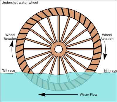
A vertically-mounted water wheel that is rotated by water striking paddles or blades at the bottom of the wheel is said to be undershot. This is generally the least efficient, oldest type of wheel.
Undershot wheels are also well suited to installation on floating platforms. The earliest were probably constructed by the Roman general Belisarius during the siege of Rome in 537.
A vertically-mounted water wheel that is rotated by falling water striking paddles, blades or buckets near the top of the wheel is said to be overshot.
In true overshot wheels the water passes over the top of the wheel, but the term is sometimes applied to backshot wheels where the water goes down behind the waterwheel.
A typical overshot wheel has the water channeled to the wheel at the top and slightly to one side in the direction of rotation. The water collects in the buckets on that side of the wheel, making it heavier than the other “empty” side. The weight turns the wheel, and the water flows out into the tail-water when the wheel rotates enough to invert the buckets.
Unlike undershot wheels, overshot wheels gain a double advantage from gravity. Not only is the force of the flowing water partially transferred to the wheel, the weight of the water descending in the wheel’s buckets also imparts additional energy.
The mechanical power derived from an overshot wheel is determined by the wheel’s physical size and the available head, so they are ideally suited to hilly or mountainous country.
Overshot wheels demand exact engineering and significant head, which usually means significant investment in constructing a dam, millpond and waterways. Sometimes the final approach of the water to the wheel is along a lengthy flume or penstock.
It combines the advantages from breastshot and overshot systems, since the full amount of the potential energy released by the falling water is harnessed as the water descends the back of the wheel.
A backshot wheel continues to function until the water in the wheel pit rises well above the height of the axle, when any other overshot wheel will be stopped or even destroyed.
A backshot wheel may also gain power from the water’s current past the bottom of the wheel, and not just the weight of the water falling in the wheel’s buckets.
A vertically-mounted water wheel design that is rotated by falling water striking buckets near the centre of the wheel’s edge, or just above it, is said to be breastshot.
The individual blades of a breastshot wheel are actually buckets, as are those of most overshot wheels, and not simple paddles like those of most undershot wheels.
Overshot and backshot wheels are the most efficient water wheel design; a backshot steel wheel can be more efficient (about 60%) than all but the most advanced and well-constructed turbines.
The development of the hydraulic water wheel design with their improved efficiency (>67%) opens up an alternative path for the installation of waterwheels in existing mills, or redevelopment of abandoned mills.
Water wheels are generally perceived as being inefficient energy converters which belong to the past, with no role for the future. But as Gerald Müller, Klemens Kauppert and Rüdiger Mach explain, they can actually be efficient and cost-effective in low head micro hydro applications
IN EUROPE, a large number of low head micro hydro power sites (head = <5m, power = <100kW) exist. Water power was a prime power source during the industrial revolution and thousands of water mills were built at low head sites. Today however, the large majority of such hydro power sources is not exploited due to the lack of a cost-effective hydraulic power converter. Recently, a number of developments appear to have opened up the possibility to generate electricity economically at low head sites. These developments include the two oldest hydraulic machines, namely water wheels and the Archimedian screw - the latter working in reverse as a power source rather than as a pump.
Water wheels are today often considered to be relics from the beginning of the industrial revolution; romantic but inefficient hydraulic machines made of wood and belonging to the past. It is generally believed that turbines are much more efficient than water wheels and subsequently took over their role as hydraulic power converters. The statistics however show a different picture. In Bavaria - a German province with an area of 70,500km2 - there were 7554 operational water wheels counted as late as 1927, with power outputs ranging from 0.75 to 75kW. In the middle of the 19th century, a high stage of development was reached when Zuppinger designed the most modern and efficient water wheel. Engineers, manufacturers and mill owners must have regarded water wheels as commercially interesting power sources. During the 1940s however, virtually all water wheels seem to have disappeared.
Today, some companies in Germany (Bega, Hydrowatt) and the US (Water Wheel Factory) are again manufacturing water wheels for electricity generation. The performance characteristics of such wheels still appear to be largely unknown. Assessment of the available power potential, comparisons with other turbine types such as the Kaplan or the Ossberger (crossflow) turbine, and even the determination of optimum operating conditions for water wheels, relies on estimates.
"Modern" water wheels, ie water wheels built using scientific principles, are made of steel and employ only the potential energy of the water since in low head flows the potential energy exceeds the kinetic energy of the flow by far. These water wheels can be divided into three fundamental types:
Water wheels were, in the large majority of cases, used to drive machinery and reached efficiencies of 75-89%. This development seems to have subsequently been forgotten.
In Karlsruhe, Germany, a small non-profit research company (IFMW - Institut für Forschung und Medien im Wasserbau) has been set up which specialises in hydraulic engineering research, and in particular in the development and promotion of low head hydro power. Within the company, a very detailed literature and market review on water wheels was conducted in order to assess the suitability of water wheels for electric power production. Since only over and undershot wheels are currently built, the discussion will be limited to those two types.
The overshot wheel receives its feeding water at the top of the wheel, catches the water in buckets or "cells" and releases the water at the lowermost possible elevation. In order to make maximum use of the energy contained in the water, the cells are shaped so as to receive the water at its natural angle of fall and then to retain it as long as possible.
Some measurements of the performance characteristics of overshot wheels were conducted in 1928, as shown in the figure below. It was found that the efficiency of a water wheel reaches 85%.
The undershot wheel was developed for the utilisation of very low heads from 0.5-2m. Whereas in ancient times the kinetic energy of the flow was utilised with a paddle-type wheel, "modern" undershot wheels built after Zuppinger"s design employ the potential energy only. The figure below shows a Zuppinger wheel with the typical "backwards" inclined curved blades.
Wheel diameters range from 4-7m, with head differences from 0.5 to 1.5m. The blades are arranged in a way so as to avoid losses at the water entry, then gradually reduce the head of water in each cell and finally to discharge the water, again with a minimum of losses. The wheel blades are curved to allow for a gentle decrease of the water level from upstream to downstream, and to minimise losses at the downstream end. In an engineering textbook from 1939 it was stated that efficiencies of 76% can be guaranteed for properly designed undershot wheels.
Recently, the undershot wheel has also experienced a small renaissance. Hydrowatt has built and installed 15 Zuppinger wheels over the last nine years, with diameters ranging from 4-7.5m, and widths of 0.5-3m. Hydraulic heads utilised ranged from 1-2.2m, with typical flow rates of 1.5-3.1 m3/sec, giving power outputs from 4-45kW of electrical power. The overall efficiency (from hydraulic power available to electric power out) was estimated as ranging from 60 to 65%.
In the UK, many smaller streams were made navigable by building weirs, many of which still exist. Generally, the head differences were in the range between 1.2-1.8m. The undershot wheel may offer a possibility to produce electric power from such weir sites. The picture below shows a typical weir situation (Eel weir on the Lagan river in Northern Ireland) with a virtual water wheel inserted. The water wheel actually fits into a "natural" environment very well, indicating that a modern machine can become a visually attractive feature too.
The Archimedian screw has been known since antiquity as a simple machine for the lifting of water. Today, Archimedian screws are still in widespread use as pumps for sewage, grain and so on. It has the advantage of being a very simple machine, with only one moving part and two bearings. It was however only recently noticed that the screw could also - in its reverse role - be employed as energy converter, termed hydraulic screw. Large scale experiments with a hydraulic screw of 8.6m length and 2.35m drop were conducted at Prague Technical University in the Czech Republic in order to assess the performance of the hydraulic screw in its power generation mode.
The screw shown in the picture above was designed for a maximum flow rate of Qmax = 0.35 m3/sec. In experiments, it reached an efficiency of 70% for Q/Qmax = 0.4, and 80% for 0.6 < Q/Qmax < 1.0. The screw rotates at 53rpm, so that fewer gear ratios than for a comparable water wheel are required to achieve the speed necessary for electricity generation. To the author"s knowledge, six hydraulic screws have been installed already. Some design guidance for hydraulic screws, based on the design experience with screw pumps and generator experiments, is also available.
The economics of micro hydro converters are a function of variable boundary conditions such as electricity prices and so on. In Germany, overshot water wheels are currently built (including installation and grid connection) for 4360-4850 US$/kW. Undershot wheels cost 7760-9700 US$/kW, Archimedian screws approximately 8250-8730 US$/kW installed capacity. For comparison, low head Kaplan turbines cost 14500-15500 US$/kW. Although water wheels and the Archimedian screw have significant cost advantages over turbines, micro hydro installations are economical only if the owner uses the generated electricity at least partially, such as for a small business. Assuming 50% of self use, 6000 hours of operation per year at nominal capacity, a small business electricity price of 11 c/kWh and a price of 7.3 c/kWh for electricity fed into the grid, the following pay back periods apply:
The general perception amongst the public as well as many engineers is that water wheels are inefficient energy converters and belong to the past. Water wheels, and in particular the overshot variety, are however very efficient and cost-effective energy converters for low head micro hydro power applications. Today, the wider application of water wheels seems to suffer from a lack of information on water wheels, the lack of any design guidance and - possibly the most important aspect - the lack of actual data about the performance of such wheels.
Apparently, no performance data at all exists for undershot wheels, whereas some information is available on overshot wheels in old reports. IFMW Karlsruhe is currently conducting a detailed review and analysis of the experimental data available on overshot wheels with a view to application of such wheels for electricity generation.
The determination of performance characteristics for overshot wheels, and the publication of such data, will be the next task of the company, followed by a detailed evaluation of undershot wheels.
The use of the Archimedian screw for power generation is a recent idea. A lot of data and design expertise does however exist from the application of the Archimedian screw as a pump, and large scale experiments in the generator role were conducted so that the design methodology of Archimedian screws is quite developed.
Ecological aspects are today a major issue in the design of hydro power installations. Both the water wheel and the Archimedian screw are considered to be very fish friendly because of the large compartments for the water and the slow speed, even for long fish like eel, thus giving them a considerable advantage over the fast rotating Kaplan turbines.

Here are some common questions about my water wheels and energy production. While not in any set order I am putting energy production questions in the lower section on this page.
*How much water does it take to turn my water wheel? Simple answer for a water wheel that is spinning freely is about 4 gpm (gallons per minute) for a 4 foot water wheel and about 8 gpm for a 8" wheel. Now the complicated part... that 4" wheel will only need about 2 gpm when it is new but as it waterlogs with time it will need a bit more water so figure needing 4 gpm. Since a water wheel will spin too fast and look bad if you give it too much water (assuming no brakes) I always recomend a valve to allow you to control the water flow over the water wheel. Give me a call and I"d be happy to describe how to put the valve in. Some pumps came with flow control valves installed in them.
* Where do I find pricing for your water wheels? While I do have set pricing for my "standard" water wheels there are many possible options for most models. By publishing my price list with all of the options and possible water wheel sizes the price list would be complicated and several pages long and I would just confuse customers. It"s easier for you to simply email or call me and tell me about your site. I will help you select the correct model and options and give you a firm price. email: Spencer@WaterWheelPlace.com
* I want the paddles angled differently. I can angle the paddles from "square" to 70 degrees. By changing the paddle angle we can control where in the wheel"s rotation the water drops out at. "Undershot" (water wheel pushed by the creek flowing under the wheel) wheels have square paddles as do some purely ornamental wheels. Most display wheels use a 35 degree paddle angle which is a nice compromise between looks and water display. Power producing water wheels have sharper angled paddles to hold the water further down in the wheel"s rotation to generate more power by harnessing the water"s weight longer.
*While not a question most people assume that I build my water wheels in my barn or garage in the back yard. Instead I"ve been renting my business location for many years and this location in Maysville GA is 100% dedicated to building water wheels. And unlike at least one competitor who claims to be a water wheel factory I don"t sub out my work to out of state manufacturers. Instead I hand select and cut every board onsite and hand fit the pieces myself in a dedicated business location. Building water wheels is all that I do, it’ not some part time hobby for me.
*Why do larger water wheels cost so much more than a smaller wheel? If you double the size of a wheel you don"t just double the materials and work. Example using "Rustic" style water wheels. A 4 foot water wheel weighs about 80 lbs. A 6 foot wheel is 240 lbs and a 8 foot standard width water wheel weighs 480 lbs. More hand selected wood, steel, and a lot more labor. Just for fun a 10" wheel weighs 950 lbs and the 12" wheels weigh in around 1500 lbs. These weights are for "standard" widths and options. Some wheels weigh a lot more and they cost more.
*What size water wheels do you build? I"ve built water wheels as small as 8 inches and as tall as 16 feet. The widest wheel I"ve built was over 6 feet wide. I build in half inch increments so if you want a 5" 8 1/2" wheel I will build it, heck, built one that size a few years ago.
*Why do your water wheels cost more than the other guy"s website? While most people are too polite to ask this question I know a lot of them wonder. The answer is short and simple. Because I refuse to build junk. I can build what they do and match their pricing but I refuse to build less than the best most durable low maintence wheels I can using the best materials and joinery; in other words I build every water wheel as if I was going to own and maintain it for many years. If you want cheap then please feel free to buy a cheap water wheel. You can always buy a replacement water wheel from me in a few years, many people do after becoming tired of trying to maintain a poorly built water wheel.
*Axle and Bearings? 1144 steel 100,000 psi tensile strength solid axles are standard with industerial grade bearings with zerk fittings. If the axle isn"t strong enough after a few years metal fatigue will break a cheap axle. You"d be surprised at how many axles and bearings I"ve sold to replace cheap axles used by other water wheel builders.

are not suitable for significant power delivery from rivers unless there is deep, fast-flowing water, as they require depth greater than the diameter to be fully immersed, and their swept area A is equal to πr2, where r = radius, so for example a turbine with a diameter of 1 m (radius r = 0.5 m) has a swept area of 0.8 m2 and requires a depth well over 1 m for optimum performance, although it will still work partially immersed.
It is claimed (https://www.smart-hydro.de/decentralized-rural-electrification-projects-worldwide/) Smart Hydro Power Decentralized Rural Electrification, 2020 that >40 of these units have been sold, making it the most successful river turbine so far produced. However it weighs 380 kg, requires 2 m depth and 2.8 m/s current velocity to achieve its 5 kW rated power output, and as shown in Table 1, costs USD $16,400. Clearly a lighter turbine able to operate in shallower water would be easier to deploy as well as being useful at a wider range of sites.
To maximize swept area in shallow water and wherever possible gain the advantage of blockage, a wide, shallow turbine is needed, or alternatively multiple small turbines arrayed across the flow. Possible options include(i) Multiple small turbines arrayed across the flow
The Idenergie turbine is basically a pair of small Darrieus turbines driving a generator directly. It costs about USD 10,000, can operate in 0.6 m depth and 1 to 3 m/s flow, and is claimed to be able to generate “up to 12 kWh per day” – so rated power is presumably 500 W in 3 m/s flow. Fig. 13
Schematic of the Kepler Energy “THAWT” (Transverse Horizontal Axis Water Turbine) contrasted with multiple axial flow turbines. (Image from the Kepler Energy websitehttps://keplerenergy.co.uk/technology.html.)
Waterotor Energy Technologies Inc, 2020a , bears a slight resemblance to a three blade Savonius rotor with a deflector plate. The Waterotor website makes extravagant claims but gives no information on performance. “Estimated target prices” are given at https://waterotor.com/products/#specsheet. Waterotor Energy Technologies Inc, 2020b
, from https://en.wikipedia.org/wiki/Water_wheel#Undershot_wheel, is effectively an HKT. They are simple but bulky for their power output, and they rotate very slowly, with optimum efficiency achieved when the paddles are moving at ½ - 1/3 of the water velocity, making them unsuitable for driving generators, compared with axial flow turbines with tip-speed ratios of 4 or more, 2.5–3 for Darrieus and 1 for Savonius rotors. Although they are normally narrow with a large diameter, there seems no reason why water wheels could not be made wide to intercept more flow in a shallow river. M. Anyi (2013) found three images of large, fairly wide floating waterwheels, one of which is shown in Fig. 23
Waterwheel diameter could be reduced to increase RPM, which would reduce the necessary gearing. The paddles could be mounted on a long, buoyant, hollow cylinder which could resist the high bending moments and enable it to float. To illustrate this concept, the author built a model 1.5 m wide from a single 6 m length of 150 mm diameter PVC pipe costing about AUD 80, but was not able to test it due to lack of support personnel.
Although waterwheels are not generally suitable for driving electrical generators, they can drive low speed pumps such as the coil pump shown in Fig. 25
Hydrostatic pressure wheels (HPWs) or hydrostatic pressure machines (HPMs), whose power depends on static head and volumetric flow through the turbine, can be very efficient (> 80%) based on head and discharge, as shown in Fig. 26
The HPW is much more compact than the traditional water wheel and may have a large cylindrical hub which can be buoyant and could be designed to withstand the large bending moments on a long turbine supported at each end. It would be possible to design a long waterwheel with high but not necessarily 100% blockage in low flows, which would achieve much higher efficiency than a stream wheel in open flow, and could float up on high flows to avoid damage.
) has a series of foils or sails mounted on a pair of endless belts, ropes or cables so they travel across the current and drive pulleys and a generator. Because they travel in an essentially straight path between pulleys, their angle of attack is essentially constant, unlike that in a Darrieus turbine, and so can be optimised, and because the pulleys driving the generator can be made small, RPM can be high compared with other turbines. However the transverse load on the blades causes very high tensile forces in the belts and radial loads on the pulley bearings. The company Tidal Sails AS has demonstrated several prototypes and patented one version, but is focused on large scale tidal flows, and the concept could be simplified and scaled down for rivers.

MILL SITE. A mill seat is a suitable place for a water mill. Amill site is the mill seat and the above mill dam. The mill dam is an interruptionin the flow of water, raises and maintains the water flow so as to makeit available to turn a water wheel.
WATER POWER SYSTEMS. Three functions of a water power system is todeliver large amounts of water to a water wheel, remove the energy fromthe water through the action of the water wheel, and disposing of the usedwater or returning it to the stream below the mill.
Water power systems consist of a number of elements. The "DAM"serves two purposes: first, to raise the water; second, it creates an impoundmentor reservoir which acts as an energy bank. Water flows the same day andnight, so it is saved during the night to be used the next day. In "SPILLWAYS", gates are used to raise or lower the water level and flow.Some are built to hold planks called "FLASH BOARDS" whichcan be put on or taken off to regulate the water level of the pond or reservoir.They are removed at times of freshets or flood stages. The "RACE"has two types, "HEAD," and "TAIL" RACE.The race carries the water from the dam to the mill site. A race may befrom a few feet to miles in length depending on the distance between thedam and the mill site. The same race may serve one mill or many mills. Atthe mouth of the race there is often a "TRASH RACK," whichstops floating logs and large debris from damaging the water wheel. Behindthe trash rack and at the end of the race are "GATES."The gates allow the mill operator to control how much water is in the raceand enters the water wheel. These two types of gates are called "HEADGATE" and "SLUICE GATE" (or "CONTROL GATE.")A "FLUME," "SLUICE" or "PEN STOCK"carries the water at an elevated level above ground to the water wheel.Flumes are either open or closed, while a pen stock is in the form of watertight pipe. Pen stocks are either cast iron pipe, sheet iron pipe, concretepipe, or the traditional wooden pipe. Later mills had dams with water beingled to the wheel by a short race or flume. After the water flows throughthe water wheel it is then returned to the stream below the mill. It flowsthrough a "TAIL RACE."
A water wheel or turbine must have the used water removed from the wheelso sufficient fall is given to the tail race to quickly carry the wateraway from the water wheel, while the head race maintains the height andlevel of the water from the dam to the wheel. There are two basic typesof water motors, "VERTICAL WATER WHEELS" and "HORIZONTALWATER WHEELS." The three common types of vertical waterwheels are the "UNDERSHOT," the "BREAST,"and the "OVERSHOT." The two common horizontal water wheelsare the "TUB WATER WHEEL," and the "TURBINE WATERWHEEL."
The two basic principles which operate on all water wheels is "IMPACT"(or "FLOW"), and "FALL." The differencein elevation between the water level in the mill pond and where it leavesthe water wheel is called the "HEAD." The end of the flumeis called the "WATER BOX." This is where the control gateis.
The general rule is that if the difference between the top of the dam andthe water surface at the tail race is less than 6 feet, and the water couldonly flow under the wheel, you would use an undershot water wheel, or horizontalwater wheel. If the difference is less than 10 feet and a flume or sluiceis able to carry water to the top of the wheel, but the water would be highenough to fill up some of the wheel"s buckets, you use a breast water wheel.If the difference is greater than 10 feet and the water would be high enoughto fill up the wheel"s buckets at the top of the water wheel, you use anovershot water wheel. Breast water wheels are more efficient than undershotwater wheels, but the overshot water wheels are the most efficient.
Until the late 1700"s millwrights thought the undershot was the most efficienttype of water wheel because the rushing and bubbling water looked powerful.In Europe the most common type of water wheel was often the undershot, becauseof its additional use in tidal and boat mills. The undershot was the basicwater wheel all millwrights learned to construct. Some millwrights in Europeonly learned to construct undershot water wheels so when they came to Americathey might construct an undershot water wheel operating from a 40 foot fall.The development of the "ELBOW BUCKET" was a great advancementover the "FLAT PADDLE" open bucket or "FLOAT,"primarily used on the undershot water wheels.
In the United Kingdom and Europe the undershot, breast shot, and pitch backwater wheels were classified as undershot because the water flowed underthese types of water wheels. There are two types of traditional undershotwater wheels, the undershot and the flutter wheel. There are three typesof traditional breast shot water wheels, the low breast, middle breast andhigh breast water wheels. There are two types of traditional overshot waterwheels, the overshot and the pitch back water wheels.
In the early 1800"s the most common water wheel used to power Americanindustry was the breast water wheel. It was not until the 1840"s did millwrightsdiscover which type of water wheel was the most efficient in different placesaccording to the available head, not the available flow. Wooden water wheelshad several drawbacks: they rotted out every ten to twenty years, and theycould not be operated in cases of ice, imbalance and debris. From the 1820"sto 1840"s water wheels began to be constructed with cast iron shafts andhubs. In the 1870"s all steel water wheels eliminated the problems withimbalance, rot, ice and debris.
Water power systems have both disadvantages and advantages. The advantagesare many. They use energy that is free, they do not pollute, they do notuse up the energy source, they return it to the stream unchanged, and theyadd oxygen to the water which helps aquatic life. However, a disadvantageis that they are effected by droughts, and floods. At one time there werethousands of small water powered mills in use. As a general rule water poweredmills from northern Virginia north into Maryland, Pennsylvania, New Jersey,New York, and New England, often had their water wheels inside of the millbuilding to protect them from ice and freezing. Mills south of northernVirginia usually had their water wheels outside of the mill structure. Historicallysome water mills constructed a roof or awning over the water wheels to protectthe wheels. These roofed covered wheels might be either wide overshot, breastshot or undershot water wheels. When a traditional wooden water wheel (whichwas enclosed within the mill) was replaced by the modern Fitz Water Wheelthey too occupied the same original space as the old wheels.
For the millwrights to harness the power of water to operate a mill, theyhad to consider several elements. The mill stream had to have a fairly dependableflow of water, and with sufficient fall to turn a water wheel without creatingthe necessity for erecting huge dams. The stream had to provide a naturaldam site for the stability of the dam once built. Broad valley floors providepoor sites for damming, whereas valleys with a natural constriction notonly limit the necessary size of the dam but provide more effective anchoringpoints for the structure. A good mill pond location immediately upstreamof the mill dam must provide for the impoundment of enough water to operatethe machinery even during periods of relative drought. In areas were theincline of the stream bed and where the ponds are confined between steepbanks,
they could not hold much water unless the dam was quite high. An area abovea natural constriction would be ideal to create a mill pond. Lower damswere better for construction and repair costs, besides the dam structurewould have considerably less risk of undue water pressure, ice jams, andflooding problems.
Mill ponds situated in narrow valleys must be backed up a considerable distancein order to impound sufficient water for the daily mill operation. The slopeof the valley floor ideally should not be raised high above the dam site.A valley floor whose slope raises high above the top of the dam will requirean equally high dam structure. The terrain should open up just above thedam site. When the pond is filled with water, it should be at a moderateelevation. Mill ponds situated in broad valleys could impound sufficientwater within a very short distance above the dam, thus reducing the areaand height of the mill dam.
Dams which are built of wood are anchored against wood and stone abutmentsto the creek banks. These abutments provide greater stability for the damstructure and tend to prevent erosion and the undermining of the dam causedby high water running around the abutments. Dams built of log or timbercribbing are filled with stone rubble and faced on the upstream side withfitted boards to resist leakage. Wood dams are not as durable as stone dams,but are very strong and are more easily rebuilt if the dam is destroyedby spring floods.
At least two outlets are required for each dam. The first is the spill waywhich allows the surplus water to flow past and over the dam once the pondis full. The second is where the water will flow to the mill via a millrace, flume, or sluice. This second outlet can be a simple ditch, oftenlined with stone or wood, or may be a complex wooden stave flume or plankbox sluice. A third outlet would be a natural overflow or seepage for therising spring floods, often away from the area of the milling complexes.
The miller who operated the mill and the millwright who constructed themill were each masters of milling. A miller was expert with his controllingdevices: the wheels, shafts gear trains, and the knowledge of how to adjusthis massive millstones to less than a wheat grains thickness apart. Well-balancedmillstones can be a paper"s thickness apart. The millwright through theapprentice system (prior to Oliver Evans" book) learned the advanced technicalknowledge necessary to milling more so then anyone in the colonies. Themillwright knew how to find natural ravines where dams could be built tofeed water to a mill as much as a mile away and maintain the height of thewater to the top of a water wheel. The millwright could lay out mill racesor canals at a constant elevation, following the natural contours of thehillsides to bring the water to the mill at a point downstream where thewater would fall or drop on the wheel. The dropping point was a "FALL"in millwright terminology. The water had to not only fall over or upon thewater wheel, but it also had to drain away downstream as efficiently aspossible. The millwright had to ensure that the water did not form a sluggishpuddle under the wheel to slow its rotation and diminish its power. Themystery once solved allowed successful placement of a mill where none wasever known to exist. Millwrights would use all of the knowledge to makeeventual solutions so that a system of shafts and gears would be used totransmit power from the water wheel to one or more sets of millstones. Asthe water wheel turned, the main shaft would be mounted to run the millstonesas well as to power additional machines of the mill by means of a systemof belts and pulleys.
Oliver Evans" book "The Young Mill-Wright and Miller"s Guide"also solved the great hydrostatic paradox of the time. The hydraulics problemwas to determine which water wheel to use, the overshot, the pitch back,the breast shot, or the under shot. And then once the water wheel type wasdetermined, it was critical to judge which size of millstones was appropriatefor the water wheel chosen. This knowledge prior to Evans was only accessibleto the master millwright. Many early colonists built both tub mills andvertical mills. A "TUB MILL" was the most primitive typeof mill, with its water wheel inside the building itself. The wheel wasmounted on the same shaft as the turning runner millstone. The wheel wasplaced in a tub to cut down on the waste of water. Since the wheel is setparallel to the ground, a tub mill was classified as a "HORIZONTALMILL." The water was funneled through a flume to the blades onthe water wheel and the sheer force of the moving water made the wheel turn.The main shaft and the runner millstone mounted on it turned at the samespeed as the water wheel. This unsophisticated system was also called a"GREEK MILL," "NORSE MILL" or "SWEDE"SMILL." This type of mill could be easily transported to a bettersite if the water power proved inadequate. A typical tub mill structuremeasured about 12 by 14 feet. The familiar "VERTICAL MILL"has its water wheel mounted on the side of the mill building perpendicularto the earth, with the axle mounted horizontally. The vertical mill wheelmade it necessary to build a gear system to change the horizontal rotationof the main shaft into a vertical motion that could be used inside the millto power the millstones. The smallest and the largest vertical mills havea gear system, incorporating wooden (squirrel cage) pinion gears (called"TRUNDLES") that were mounted at the bottom of the shaftsthat turned the runner millstone. The colonial millwright could plan a millthat would not only turn corners with motive power, but also make the millstonesrevolve at a rate faster than the slow but steady turning water wheel. WhenOliver Evans patented his improvements in 1787 they increased the efficiencyand cost effectiveness of mills. Oliver Evans published his book on millconstruction and operation in 1795. This handy guide for putting up millsmay account for the underlying similarity among 19th century mills thaton the exterior look very different. Many millwrights simply would copythe cross-section drawings of the layout of Oliver Evans" machinery directlyfrom his book.
Some of the terminology of flour milling may be perplexing to the modernreader. For example, the mill building itself was long referred to as "THEMILL HOUSE," but later "THE MILL HOUSE"came to mean the "MILLER"S HOUSE," or dwelling rather thanthe functioning mill. "A SET OF MILLS" often meant merelyone mill building, possibly equipped with more than one set of grindingmechanisms, often meaning equipped with a saw mill besides a grinding operation."A DOUBLE MILL" was referred to in the plural althoughonly one mill structure occupied that particular site. A double mill maymean two water wheels operating two separate sets of gearing and millstones,or a double mill may also mean a mill which includes two separate millingoperations such as grinding and sawing mills in the same structure. In describingthe mill"s machinery or equipment of a mill, a "RUN OF STONES"meant one complete set of grinding stones, the upper "RUNNER"stone and the lower "BED" stone. A "TWO RUN OFSTONES" indicated two complete and separate units in the same mill,four millstones in two pairs. The "RUN" of the mill iswhat the mill grinds or the amount of grain ground by the millstones ina given period. A "RUN" is another name for a "PAIR"of millstones. A "MILL RUN" is another name forthe "HEAD RACE" and also "MILL RUN" refersto what the mill was grinding each day. There is the "HEAD"or fall of water and the "head" of the barrel which the millerplaces his flour. To run the millstones too "THIN" means to runthe stones with too little feed which could ruin the millstones. A "MILLBILL" is not a statement of charges or a list of items but anothername for a "MILL PICK" which is used to "DRESS"or sharpen the millstones. Going "THROUGH THE MILL" doesnot mean touring the mill structure but the grain that has traveled "THROUGHTHE MILLSTONES."
This water wheel suffers from the most common problem with wooden waterwheels. The water enters the buckets forward of the vertical center of thewater wheel. The water should leave the end of the chute behind the verticalcenter so the water wheel gets full benefit of the fall of the water. Inmay water wheels that the water enters the buckets in front of the verticalcenter much of the water can fly over or overshoot the wheel and be wasted.See:Fitz Steel Overshoot Water Wheels, Bulletin No. 70, Decmeber1928, by the Fitz Water Wheel Company, ComparisonWith Wood Wheels
2. The greater the height of the fall, the less the volume of water requiredto obtain a given amount of power, thus reducing the size and expense ofthe hydraulic facilities from the millpond and tail race.
4. Typical mill installation consists of a water wheel erected besides orbeneath a mill structure; a dam at some suitable point up stream to divertmore or less of the flow into the headrace; and to increase the amount offall (usually to create a pond for storage of the nighttime stream flow);a canal called a millrace, or headrace, to carry the water to the mill withminimal loss of fall; a pen stock, or sluice, with gate, to convey the waterto the wheel; and a tail race to carry the water discharged from the wheelwith energy largely spent, back to the stream below the mill. A typicalmill race and sluice box has 1" to 0" fall.
5. Further appurtenances are needed such as gates to regulate water flow,waste ways for contingencies of flood and high water, and trash racks tokeep floating debris and ice from clogging pen stocks and water wheel.
6. Dams are a barrier constructed of locally available material, such asstone, timber, brush and soil, in various arrangements erected across thestream with its ends well anchored in the stream banks on either side. Damsmay be a low structure. They are intended to divert water into a head raceto maintain the fall and develop horse power.
7. Dams raise the water level and backs water up stream depending upon theheight of the dam structure and the character of the local terrain. Theycreate a storage reservoir known as a millpond. This accumulated water willrun the mill for hours.
10. Crib dams use narrow channels and high banks on each side. The dam consistsof two cribs secured to the natural embankment made of material that thewater will not penetrate. The two cribs have a V shaped connection betweenthem with an apron extending 3 or 4 feet forward of the cribs. The V shapeand the two cribs form an arch which holds the pressure of the water
13. Abutments at the stream banks and tumbling aprons of timber dams arecovered with planks or rocks to prevent the water passing over the dam fromundermining the dams foundations.
14. The dam should not be too close to the mill. A breach or leak on thefore bay may wash away the mill. The mill should be placed to protect itfrom floods and high water.
1. Type of water wheel: a) horizontal: norse mill, tub wheel, turbine; b)vertical: undershot, flutter, low breast, mid breast, high breast, pitchback, overshot
Head would equal the 16 foot diameter water wheel plus one foot below thewater wheel for the water to flow into the tail race, one foot of waterabove the water wheel for the water to enter the water wheel, and threefeet of water standing in the sluice box. This would equal 21 feet of neededhead.

(This introductory overview to waterwheels is the first of a three-part series. The second installment [Issue No.17] will be about undershot and no-head wheels, and the third installment [Issue No. 18] will deal with overshot wheels. Editor)
The creak of an old, wooden moss-covered wheel lazily driving a gristmill in a long lost past is how most people think of a small scale water power. Of course water power is old. Historical records put it at around 4000 years old. While that makes it an ancient technology, that doesn’t make it an antique technology. If you have ever considered windmills, think of a water wheel as a windmill that uses a fluid 824 times as dense. In other words, 824 times as powerful. On the negative side, you need access to a good stream, while the wind is everywhere. I am making this comparison to show that water power isn’t any more complicated than wind power to understand.
Waterwheels run because “gravity” causes a “mass” of water to fall some distance (HEAD). This energy is absorbed by the wheel to do work. There is more than one way to absorb the energy, so wheels have evolved into two classes:
Reaction, uses the moving water to create a pressure differential like an airplane wing. These are correctly called “turbine’s.” A propeller is the most common example of the type.
For this reason I recommendimpulse type water wheels. These function by transferring the momentum of the moving water to the machine. The energy transfer is similar to one billiard ball transferring its energy to another. Because of this, impulse wheels have a very high efficiency, and more importantly, have a constant efficiency over varying stream conditions.
On a small, variable stream (a typical home/farm stream) an impulse wheel can produce more than twice the kilowatt hours of a reaction wheel. Impulse wheels are available in several types, each designed for a specific type of stream.
No-head: If you have a stream with an average velocity of 4 feet per second or higher (preferably higher), you can use a no-head water motor. These are a relatively new innovation. While they are somewhat inefficient compared to more traditional designs, they have the advantage that they do not need a dam of any sort. The time, expense and just plain hassles associated with building a dam make these designs very desirable. There are three choices:
A FITZ C-Rotor and the Scheider Lift Translator are autonomous generators, containing the wheel, generator, and regulator in a single unit. You just place one in a stream and connect the power cable to a load. Both designs are quite cost-effective as a personal power source.
Undershot wheels range from simple paddle wheels placed in a stream to Poncelot Wheels. They were developed in France during the 18th century. They are good for small to medium flows and heads from 1 foot to 12 feet. If properly designed, a Poncelot can be 85% efficient or more. Even an amateur-built wheel can be over 75% efficient.
Overshot wheels are the kind people associate with Currier & Ives engravings. While many were made of wood, after 1840 most were made of metal. For small streams and heads up to 25 feet, these are still the best choice for a home/farm user. The old FITZ I-X-L designed in 1862 was tested at the University of Wisconsin in 1913. It proved to be 93% efficient.
Crossflow turbines are incorrectly called a turbine since they work on the impulse principal. They can best be described as undershot wheels in a can. They are useful for small to large flows and heads from 10 feet to 100 feet. They are close tolerance devices so we wouldn’t recommend this design to an amateur builder unless you have some machining experience. A Pelton wheel is a high head variant of the crossflow, best used with heads of 50 feet or higher.
Surprisingly, wheel horsepower and efficiency are not the most important factors. This is because stream flows vary over the year. The best choice is the wheel that delivers 50% or more of the theoretical power of the stream. In other words, the total annual production should be at least HALF of the production you would get if the wheel ran at full power all year long.
For example, there are 8760 hours in a year. If you had a 10


 8613371530291