
overshot weir free sample
A weir is a barrier across the width of a river or stream that alters the characteristics of the flow and usually results in a change in the height of the water level. Several types of weirs are designed for application in natural channels and laboratory flumes. Weirs can be broad-crested, short-crested, or sharp-crested. Sharp-crested weirs, commonly referred to as notches, are manufactured from sharp-edged thin plates. The relationship between the flow rate and water depth above the weir can be derived by applying the Bernoulli’s equation and by making some assumptions with regard to head loss and pressure distribution of the flow passing over the weir. A coefficient of discharge needs to be determined experimentally for each weir to account for errors in estimating the flow rate that is due to these assumptions.
Weirs are commonly used to measure or regulate flow in rivers, streams, irrigation canals, etc. Installing a weir in an open channel system causes critical depth to form over the weir. Since there is a unique relationship between the critical depth and discharge, a weir can be designed as a flow-measuring device. Weirs are also built to raise the water level in a channel to divert the flow to irrigation systems that are located at higher elevations.
The flow over the weir apparatus includes the following elements that are used in conjunction with the flow channel in the molded bench top of the hydraulics bench (Figure 9.1).
The depth of water above the base of a weir is related to the flow rate through it; therefore, the weir can be used as a flow measuring device. The relationships of flow over weirs can be obtained by applying the energy equation from a point well upstream of the weir to a point just above the weir crest. This approach requires a number of assumptions, and it yields the following results:
Note:The surface of the water will fall as it approaches the weir. This is particularly noticeable at high flow rates by high heads. To obtain an accurate measurement of the undisturbed water level above the crest of the weir, it is necessary to place the measuring gauge at a distance of at least three times the head above the weir.
Calculate discharge (Q) and head (h) for each experiment, and record them in the Result Tables. For calculation purposes, the depth of the water above the weir is the difference between each water level reading and the datum reading, i.e.,H = h-ho
Plot a graph of Q (y-axis) against H 3/2(x-axis) for the rectangular weir and Q against H 5/2for the triangular weir. Use a linear function to plot the best fit, and express the relationship between Q andHnand in the form of:
Compare the results for Cdof the weirs utilized in this experiment with those you may find in a reliable source (e.g., textbooks). Include in your report a copy of the tables or graphs you have used for textbook values of Cd.
{ "01.10:_Experiment_%2310:_Pumps" : "property get [Map MindTouch.Deki.Logic.ExtensionProcessorQueryProvider+<>c__DisplayClass228_0.
https://eng.libretexts.org/@app/auth/3/login?returnto=https%3A%2F%2Feng.libretexts.org%2FBookshelves%2FCivil_Engineering%2FBook%253A_Applied_Fluid_Mechanics_Lab_Manual_(Ahmari_and_Kabir)%2F01%253A_Lab_Manual%2F01.9%253A_Experiment_%25239%253A_Flow_Over_Weirs
WEIRS ...................................................................................................................................................... 4
CRUMP WEIR......................................................................................................................................... 15

A weir is a concrete or masonry structure which is constructed across the open channel (such as a river) to change its water flow characteristics. Weirs are constructed as an obstruction to flow of water. These are commonly used to measure the volumetric rate of water flow, prevent flooding and make rivers navigable.
To find the discharge over rectangular weir, consider an elementary horizontal strip of water thickness dh and length L at a depth h from the water surface.
Trapezoidal weir is also called as Cippoletti weir. This is trapezoidal in shape and is the modification of rectangular weir with slightly higher capacity for same crest strength.
The weir plate is bevelled at the crest edges to obtain necessary thickness. And weir plate should be made of smooth metal which is free from rust and nicks.

HEC-RAS has the ability to model inline dams, weirs, and gated structures with radial gates (often called tainter gates), vertical lift gates (sluice gates), overflow gates (open to the air or with a closed top), gates modeled with user defined curves, culverts, culverts with flap gates, user defined outlet rating curves, and user specified outlet time series. The spillway crest of the gates can be modeled as an ogee shape, broad crested weir, or a sharp crested weir shape.
Enter all of the data for the Inline structure. This data will include a Weir/Embankment profile, any gated spillways that you may be modeling, culverts, and/or outlet rating curves. All of the outlet types are optional, except the embankment profile of the inline structure. If the user does not enter any gated spillways, culverts, etc…, then the program assumes that there is only an inline weir.
The Embankment and Weir data are entered together, and are used to describe the embankment blocking the stream as well as any uncontrolled overflow weirs. To enter the weir and embankment data, press the Weir/Embankment button and the editor will appear (see figure below). The Weir/Embankment Data editor is similar to the Deck/Roadway editor for bridges and culverts. The data on the Weir/Embankment editor is the following:
Distance - The distance field is used to enter the distance between the upstream side of the Weir/Embankment (the top of the embankment) and the cross section immediately upstream of the structure. This distance is entered in feet (or meters for metric).
Width - The width field is used to enter the width of the top of the embankment along the stream. The distance between the top of the downstream side of the embankment and the downstream bounding cross section will equal the main channel reach length of the upstream cross section minus the sum of the weir/embankment "width" and the "distance" between the embankment and the upstream section. The width of the embankment should be entered in feet (meters for metric).
Station and Elevation Coordinates - This table is used to define the geometry of the Weir and the Embankment. The information is entered from left to right in cross section stationing. The user enters stations and elevations of the top of the embankment and weir. The stationing does not have to equal the stations in the bounding cross section, but it must be based on the same origin. Everything below these elevations will be filled in down to the ground. The Del Row and Ins Row buttons allow the user to delete and insert rows.
Weir Crest Shape - When submergence occurs over the weir there are two choices available to figure out how much the weir coefficient should be reduced due to the submergence. These two criteria are based on the shape of the weir. The first method is based on work that was done on a trapezoidal shaped broad crested weir (FHWA, 1978). The second criterion was developed for an Ogee spillway shape (COE, 1965). The user should pick the criterion that best matches their problem. If the user selects the Ogee Spillway shape, then some additional information is required. For an Ogee shaped weir the user must enter the "Spillway Approach Height" and the "Design Energy Head". The spillway approach height is equal to the elevation of the spillway crest minus the mean elevation of the ground just upstream of the spillway. The design energy head is equal to the energy grade line elevation (at the design discharge) minus the elevation of the spillway crest. In addition to these two parameters, the user has the option to have the program calculate the weir coefficient at the design discharge. This is accomplished by pressing the Cd button. Once this button is pressed, the program will compute a weir coefficient for the Ogee spillway based on the design head. During the weir calculations, this coefficient will fluctuate based on the actual head going over the spillway. The curves used for calculating the Ogee spillway coefficient at design head, and discharges other than design head, were taken from the Bureau of Reclamation publication "Design of Small Dams", Figures 249 and 250 on page 378 (Bureau of Reclamation, 1977).
In addition to uncontrolled overflow weirs, the user can add gated spillways (this is optional). To add gated spillways to the structure, press the Gate button on the Inline Structure data editor. Once this button is pressed, the gated editor will appear as shown in the figure below (Except yours will be blank until you have entered some data).
If a gate is opened to the point at which the top of the gate is no longer touching the water (or if an open air overflow gate is being used), then the flow through the gate is modeled as weir flow. The program will automatically transition from gate flow to weir flow when the upstream head is between 1.0 to 1.1 times the height of the gate opening. The following parameters are required to model weir flow through the gate opening.
Weir Shape - This parameter allows the user to select between a Broad Crested shape weir, an Ogee shaped weir, or a sharp crested weir. Depending on which shape is selected, the program will use a different submergence criteria during the calculations. In addition to the submergence criteria, if the user selects the Ogee shape, the program will bring up additional data entry fields that must be entered by the user. For the ogee weir shape, the additional fields are the Spillway Approach Height and the Design Energy Head, which are explained below. Once these fields are entered, the user should press the button labeled Cd. When this button is pressed, the program will compute a weir coefficient for the Ogee spillway based on the design head. During the weir calculations, this coefficient will fluctuate based on the actual head going over the gated spillway. The curves used for calculating the Ogee spillway coefficient at design head, and discharges other than design head, work taken from the Bureau of Reclamation publication "Design of Small Dams", Figures 249 and 250 on page 378 (Bureau of Reclamation, 1977).
Weir Method – This field is only available when the Sharp Crested Weir shape is selected. If a sharp crested weir shape is selected, then the user has three choices for defining the weir coefficient: User Entered Coefficient; Compute with Rehbock equation; and Compute with Kindsvater-Carter Equation. If the "User Entered Coefficient" option is selected, then the user simple enters a coefficient that will be used for weir flow through the gate, for all head ranges. If the "Rehbock equation" is selected, the user is asked to enter a spillway approach height (explained below), and the weir coefficient is then computed with the Rehbock equation. If the "Kindsvater-Carter equation" is selected, then the user must enter a spillway approach height, and also select which form of the Kindsvater- Carter equation will be used. The form of the Kindsvater-Carter equation is based on selecting one of eleven equations that are based on varying L/b. Where L is the width of the gate opening, and b is the top width of the approaching water upstream of the gate. If more than one gate is defined at a particular opening, you must figure out an average approach width for flow going to each gate.
Weir Coefficient - This field is used for entering a weir coefficient that will be used for the gate opening. This coefficient will only be used when the gate is opened to an elevation higher than the upstream water surface elevation. When this occurs, the flow through the gate is calculated as weir flow. If the Kindsvater-Carter equation is selected, then this field is used to select which form of the equation will be used to compute the coefficient.
If a user has an outlet type that does not exist in HEC-RAS, or cannot be modeled accurately with the available weirs, gates, and culverts, then an outlet rating curve can be used to model that specific outlet. The Outlet Rating curve can be based on upstream water surface elevations versus outlet flow, or it can be based on upstream total flow versus the flow through the outlet. This method does not take into account downstream tailwater influences on the flow rate.

The gated spillway and weir option within HEC-RAS can be used to model inline (structures across the main stream) or lateral (structures along the side of the stream) weirs, gated spillways, or a combination of both. An example of a dam with a gated spillways and overflow weir is shown in the figure below.
The overflow weir capability can be used by itself or in conjunction with the gated spillway option (as well as the other outlet types available in Inline and Lateral structures). The overflow weir is entered as a series of station and elevation points across the stream, which allows for complicated weir shapes. The user must specify if the weir is broad crested, ogee shape, or sharp crested. The software has the ability to account for submergence due to the downstream tailwater. Additionally, if the weir has an ogee shaped crest, the program can calculate the appropriate weir coefficient for a given design head. The weir coefficient will automatically be decreased or increased when the actual head is lower or higher than the design head.

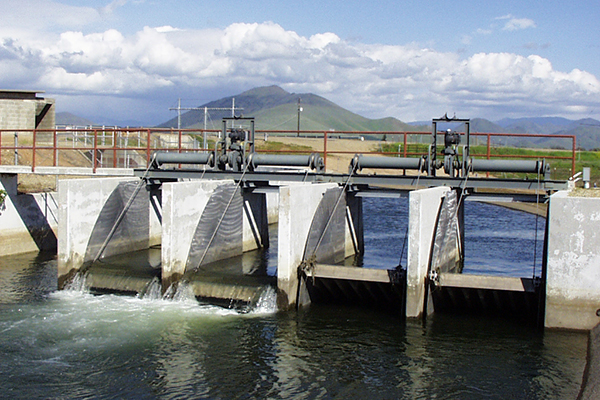
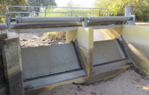
Overshot gates (also known as pivoting weir gates) are used to control upstream water levels. Versatility, efficiency, and safety are the primary reasons the Fresno Overshot Gate is the method of choice for municipal, agricultural, and industrial canal water control.


 8613371530291