
overshot wheel in stock
RMTXH39N–Multiple suction pumps, powered by an overshot water wheel through a spur wheel and lantern, being used to raise water from a mine. From "De re metallica", by Agricola, pseudonym of Georg Bauer (Basle, 1556). Woodcut.
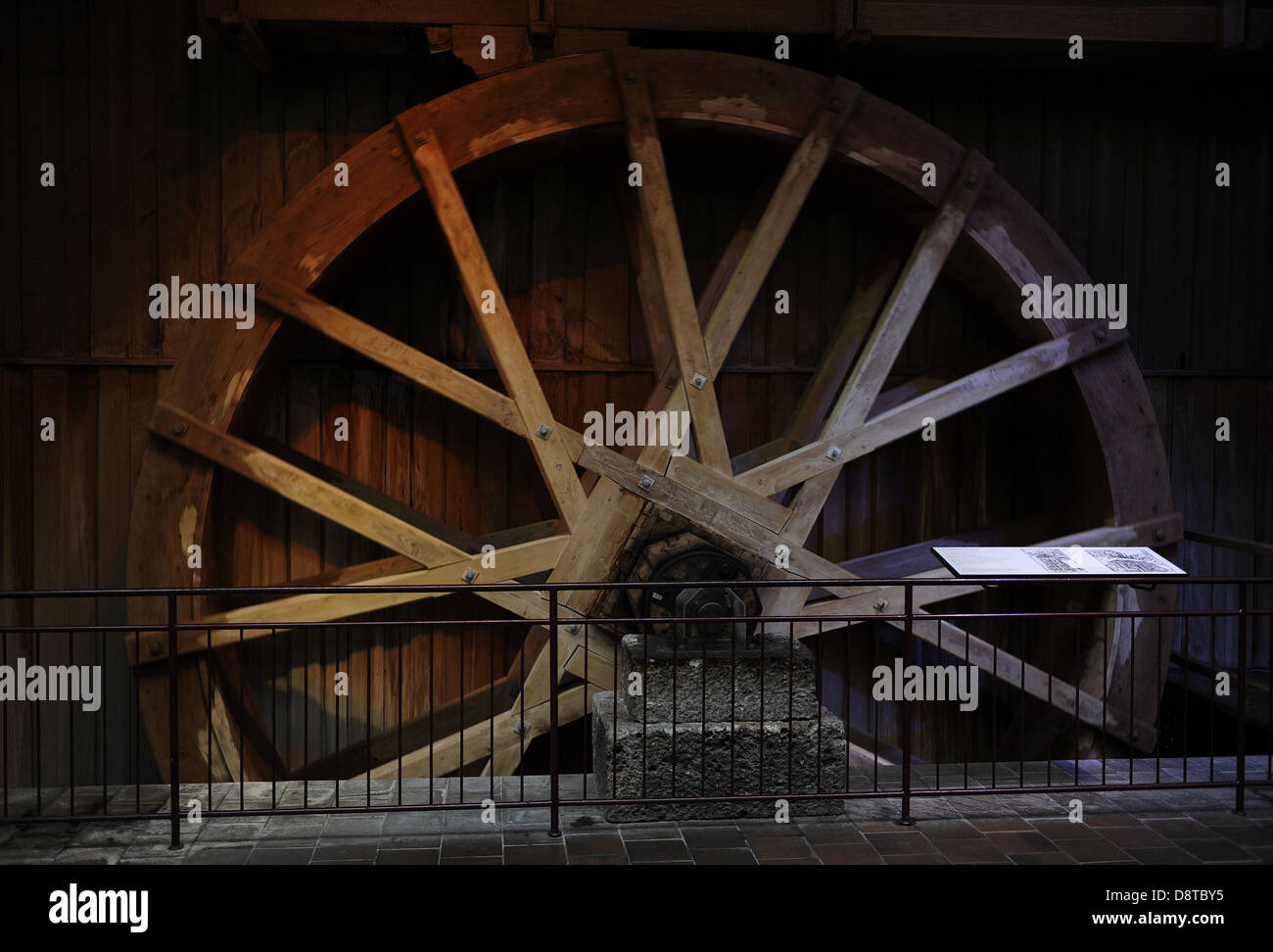
RMMPAKW1–. Deutsch: Wassermühle mit einem oberschlächtigen Wasserrad. British Library, Cotton Manuscript Cleopatra C XI, fol 10. English: Mill with overshoot wheel. British Library, Cotton Manuscript Cleopatra C XI, fol 10. between circa 1220 and circa 1230. Unknown 879 Medieval mill with overshot wheel
RF2B770CM–An image of the overshot wheel that operates machinery by water power, receiving water at the top, it shows the water wheel power of generation in it,
RM2AMM7ET–the overshot water wheel at the Maiermühle in TeisendorfThe mill has been in the possession of the Mühlbacher family since 1769 - the 8th generation - the oldest machine family from 1920the mill has existed at least since the Middle Ages - the water wheel was bought second-hand in 1930 (at that time it was already 50 years old and comes from Franconia) - the arms are made of oak wood, the wheel itself is made of iron - a centimetre thick layer of lime protects against rust20 grinding passes are made from the grain fine more [automated translation]
RMTXH3F5–Draining mine workings by means of a battery of three pumps. The axle, B, is powered by an overshot water wheel. The cams on the axle raise and lower the piston rods by means of tappets. C is the bottom of the pipe which is encased in the basket, D. From "De re metallica", by Agricola, pseudonym of Georg Bauer (Basle, 1556). Woodcut.
RF2C9CE04–Overshot wheel, gives the greatest power with the least quantity of waterand so mainly used when circumstances will permit, or where there is a consid
RMP774N6–. English: Mining operation, Glacier Creek, July 14, 1906 . English: Caption on image: Overshot wheel and China pump operated by A.F. Guinan. Glacier Creek, July 14th 1906. Photo by F.H. Nowell, Nome, 4961 Subjects (LCTGM): Mining equipment--Alaska Subjects (LCSH): Gold mines and mining--Alaska . 1906 9 Mining operation, Glacier Creek, July 14, 1906 (NOWELL 182)
RM2EAERG7–Bagging up the flour produced by Lurgashall Mill. Weald and Downland Open Air Museum, Singleton, Nr. Chichester, West Sussex. The overshot wheel powe
RMTXH39C–A rag-and-chain pump powered by an overshot water wheel being used to drain a mine. On the right is a detail of the tube of the pump. From "De re metallica", by Agricola, pseudonym of Georg Bauer (Basle, 1556). Woodcut.
RF2CB7RM0–Overshot water wheel and flume at historic Oblazy Water Mill at Kvacianka river, Kvacany Valley (Kvačianska dolina), Liptov area, Zilina Region, Slovakia
RMPPEK4E–The overshot waterwheel on the Maiermuehle in Teisendorf. Since 1769 the mill is owned by the Muehlbach family - in the 8th generation - the oldest machine dates back to 1920. The mill has existed at least since the Middle Ages - the waterwheel was used in 1930 (it was already 50 years old and Comes from the Franconian region). The arms are made of oak, the wheel itself is made of iron - a 1 centimeter thick layer protects it against rust. Fine flour is obtained from the grain after 20 grinding processes.
RF2D74G56–Paternoster work with overshot water wheel / Paternosterwerk mit oberschlächtigem Wasserrad, Historisch, historical, digital improved reproduction of an original from the 19th century / digitale Reproduktion einer Originalvorlage aus dem 19. Jahrhundert
RMMR3X1X–Diagram depicting various forms of water wheels including at Fig. 5, a pitch back overshot wheel. Created by Abraham Rees (1743-1825) a Welsh nonconformist minister, and compiler of Rees"s Cyclopædia. Dated 19th century
RF2CB7RMG–Tourist coming out under flume, leaking water, overshot water wheel at historic Oblazy Water Mill at Kvacianka river, Kvacany Valley (Kvačianska dolina), Liptov area, Zilina Region, Slovakia
RMRJHB0B–Drawing showing Pump driven by overshot water wheel, used to raise water into a reservoir, to operate the ornamental fountain in the background. From Georg Andreas Bockler; Theatrum Machinarum Novum, Nuremberg, 1673
RMD95KFA–A rag-and-chain pump powered by an overshot water wheel being used to drain a mine. On the right is a detail of the tube of the pump. From "De re metallica", by Agricola, pseudonym of Georg Bauer (Basle, 1556). Woodcut.
RMTX1CWX–The overshot water wheel and lade at Coldstream Mill in North Ayrshire. Circa 1999.; 11 February 2007 (original upload date); Transferred from en.pedia to Commons.; Rosser1954 at English pedia;
RMD95KD7–Stamping mills powered by and overshot water wheel being used to crush ore to begin the process of extracting metal from the ore won from a mine. From "De re metallica", by Agricola, pseudonym of Georg Bauer (Basle, 1556). Woodcut. Mining. Metal. Power. Water.
RMTXGY3X–Mine being drained by a rag-and-chain pump powered by overshot water wheel. At right is detail of section of pipe K From "Agricola De re metallica" 1556 Basle
RM2BA554H–"Deutsch: Oberschlächtiges Wasserrad neben dem Alten Rathaus in Tambach-Dietharz, Deutschland, 2007.English: Overshot water wheel next to old townhall in Tambach-Dietharz, Germany, 2007.; 29 September 2007; Own work; Sebastian Wallroth; "
RMD96J1R–Mule-powered sugar mill with vertical rollers (top). Sugar mill with vertical rollers powered by overshot waterwheel (bottom) West Indies. Copperplate engraving, London, 1764.
RMPPEK4E–The overshot waterwheel on the Maiermuehle in Teisendorf. Since 1769 the mill is owned by the Muehlbach family - in the 8th generation - the oldest machine dates back to 1920. The mill has existed at least since the Middle Ages - the waterwheel was used in 1930 (it was already 50 years old and Comes from the Franconian region). The arms are made of oak, the wheel itself is made of iron - a 1 centimeter thick layer protects it against rust. Fine flour is obtained from the grain after 20 grinding processes.
RMHTMK4N–Mule-powered sugar mill with vertical rollers (top). Sugar mill with vertical rollers powered by overshot waterwheel (bottom) West Indies. Copperplate engraving, London, 1764
RMTX1CYY–The overshot waterwheel and Water Wall at Coldstream Mill in North Ayrshire near Beith, circa 1999.; 11 February 2007 (original upload date); Transferred from en.pedia to Commons.; Rosser1954 at English pedia;
RMTXGY73–Reversible hoist for raising leather buckets from mine shaft powered by overshot waterwheel. Man in hut at O opens and shuts water races to stop and start double row of buckets From Agricola "De re metallica" 1556 Woodcut Basle
RM2DJ3DWW–An Overshot Mill, James Ward, 1769–1859, British, between 1802 and 1807, Oil on panel, Support (PTG): 10 7/8 x 13 1/8 inches (27.6 x 33.3 cm), costume, cottage, genre subject, ladder, landscape, man, peasants, straw, stream, washing, water mill, waterwheel, woman, workers
RMHEK71X–This is the 40-foot overshot waterwheel Oct. 27, 2010 at Mill Springs Mill, which is a historical gristmill from the 1800s that is preserved and administered by the U.S. Army Corps of Engineers Nashville District. The mill is located off Kentucky Highway 90 between Burnside and Monticello on the banks of scenic Lake Cumberland in Mill Springs, Ky. (USACE photo by Lee Roberts) Public get historic treat at Corps gristmill 338173
RM2A5YMD2–Reversible hoist for raising leather buckets from mine shaft powered by overshot waterwheel. Man in hut at O opens and shuts water races to stop and start double row of buckets. From Agricola "De re metallica" Basle 1556. Woodcut.
RMD98MMR–Landscape with Village Fete" (detail). Oil on canvas. Centre right is a forge or furnace powered by an overshot waterwheel. Lucas van Valckenhorgh (1530-1597) Flemish painter. Rocks Industry Leat
RM2EAERHM–Inside Lurgashall Water Mill, showing the mechanism working. Overshot waterwheel powers two pairs of mill stones, a sack hoist and a grain sifter, or
RFPYH2JC–STELLENBOSCH, SOUTH AFRICA, AUGUST 16, 2018: Information board for the historic overshot waterwheel of the Nieuwe Molen (mill) in Stellenbosch in the
RMD969NG–Reversible hoist for raising leather buckets from mine shaft powered by overshot waterwheel. Man in hut at O opens and shuts water races to stop and start double row of buckets. From Agricola "De re metallica" Basle 1556. Woodcut.
RF2CB7RX0–Overshot water wheel at historic Oblazy Water Mill at Kvacianka river, Kvacany Valley (Kvačianska dolina), Liptov area, Zilina Region, Slovakia
RFPYFT3P–STELLENBOSCH, SOUTH AFRICA, AUGUST 16, 2018: The historic overshot waterwheel of the Nieuwe Molen (mill) in Stellenbosch in the Western Cape Province.
RF2CB7RT6–Overshot water wheel at historic Oblazy Water Mill at Kvacianka river, Kvacany Valley (Kvačianska dolina), Liptov area, Zilina Region, Slovakia
RMP6HBP0–Overshot and undershot waterwheels, 19th century, including examples designed by John Smeaton and Peter Nouaille. Copperplate engraving by W. Lowry after an Illustration by J. Farey from Abraham Rees" "Cyclopedia or Universal Dictionary," London, 1817.
RMTDHWBY–OVERSHOT, METAL WATERWHEEL THAT DROVE COFFEE HUSKER - Hacienda Cafetalera Santa Clara, Coffee Mill, KM 19, PR Route 372, Hacienda La Juanita, Yauco Municipio, PR; Cary, Brian, transmitter; Boucher, Jack E, photographer
RFRKJHJG–STELLENBOSCH, SOUTH AFRICA, AUGUST 16, 2018: The historic overshot waterwheel of the Nieuwe Molen (mill) in Stellenbosch in the Western Cape Province.
RM2BEWR4N–Century-old wooden waterwheel grist mill at Stone Mountain Park in Atlanta, Georgia. The grist mill was originally located in Ellijay, Georgia.
RMRFFTMN–An Overshot Mill. Date/Period: Between 1802 and 1807. Painting. Oil on panel. Height: 276 mm (10.86 in); Width: 333 mm (13.11 in). Author: James Ward.

The overshot wheel is the most common wheel seen in North America. It is a gravity wheel. This means that it harnesses the force of gravity acting vertically on the water as it travels from the top to the bottom of the wheel. Properly designed for a particular site, and correctly timed, an overshot The overshot wheel is most effective when it turns as slowly as possible and can still handle the total flow of water available to it. The optimal rim speed should be only about 3 feet per second. The larger the wheel the slower it will need to turn. The incoming water must be traveling about three times the rim speed of the wheel so that it can fill the buckets effectively. This requires a foot or more of head above the wheel, usually controlled by a gate.
When the head, or fall of water was not sufficient for a large diameter overshot wheel, the breast wheel often is used. This is halfway between the overshot and undershot wheels. Water strikes the buckets of the breast wheel about midway between top and bottom, using the weight of the water for a 90 degree segment of arc. Their efficiency is far less than the overshot, which uses the weight of the water for a full 180 degrees.
This type of waterwheel relies on the flow of water, coming along the base flowing at a good rate of speed to push or thrust the waterwheel. This type of waterwheel is used on mills built on rivers or streams that do not have any height or (head). Undershot wheels are normally narrow and have to have the channel walls very close to the sides of the wheel to maximize the flow of water to pass through the wheels to generate power. This type of wheel is generally the least efficient type of wheel - usually in the 30-50% range. The exception to this is the Poncelet wheel that can get up to 80% efficiency if the channel is properly constructed and the buckets are designed right.
This type of waterwheel relies on the flow of water, generally in an open stream. This type of wheel is generally the least efficient type of wheel - usually in the 30-40% range. The exception to this is the Poncelet wheel that can get up to 80% efficiency if the channel is properly constructed and the buckets are designed right.
Many micro hydro electric generation strategies have evolved in recent years. Helical Ribbons, Under Water Blade Turbines, Tide and Wave action mechanical generators. Our approach is to simplify sustainable micro hydroelectric water wheel construction and improve the efficiency of energy generation. Our recent association with Ticho Industries in Italy has produced a new form of micro hydro waterwheels with a high efficiency electric generator mounted safely on the axle completely within the water wheel structure. This design simplifies micro hydro water wheel design for optimal water flow location mounting, system longevity, ease of maintenance and simplified electro mechanical connection. Our new design was created for city and rural stream based flows - including the outflows from major hydro electric dams, major navigation and irrigation dams, manufacturing and water treatment facilities.
A water wheel is a machine for converting the energy of flowing or falling water into useful forms of power, often in a watermill. A water wheel consists of a wheel (usually constructed from wood or metal), with a number of blades or buckets arranged on the outside rim forming the driving car. Water wheels were still in commercial use well into the 20th century but they are no longer in common use. Uses included milling flour in gristmills, grinding wood into pulp for papermaking, hammering wrought iron, machining, ore crushing and pounding fibre for use in the manufacture of cloth.
Some water wheels are fed by water from a mill pond, which is formed when a flowing stream is dammed. A channel for the water flowing to or from a water wheel is called a mill race. The race bringing water from the mill pond to the water wheel is a headrace; the one carrying water after it has left the wheel is commonly referred to as a tailrace.
Waterwheels were used for various purposes from agriculture to metallurgy in ancient civilizations spanning the Hellenistic Greek world, Rome, China and India. Waterwheels saw continued use in the Post-classical age, like the Middle Ages of Europe and the Islamic Golden Age, but also elsewhere. In the mid to late 18th century John Smeaton"s scientific investigation of the water wheel led to significant increases in efficiency supplying much needed power for the Industrial Revolution.turbine, developed by Benoît Fourneyron, beginning with his first model in 1827.elevations, that exceed the capability of practical-sized waterwheels.
The main difficulty of water wheels is their dependence on flowing water, which limits where they can be located. Modern hydroelectric dams can be viewed as the descendants of the water wheel, as they too take advantage of the movement of water downhill.
Overshot and backshot water wheels are typically used where the available height difference is more than a couple of meters. Breastshot wheels are more suited to large flows with a moderate head. Undershot and stream wheel use large flows at little or no head.
There is often an associated millpond, a reservoir for storing water and hence energy until it is needed. Larger heads store more gravitational potential energy for the same amount of water so the reservoirs for overshot and backshot wheels tend to be smaller than for breast shot wheels.
Overshot and pitchback water wheels are suitable where there is a small stream with a height difference of more than 2 metres (6.5 ft), often in association with a small reservoir. Breastshot and undershot wheels can be used on rivers or high volume flows with large reservoirs.
Stream wheels are cheaper and simpler to build and have less of an environmental impact, than other types of wheels. They do not constitute a major change of the river. Their disadvantages are their low efficiency, which means that they generate less power and can only be used where the flow rate is sufficient. A typical flat board undershot wheel uses about 20 percent of the energy in the flow of water striking the wheel as measured by English civil engineer John Smeaton in the 18th century.
Stream wheels mounted on floating platforms are often referred to as hip wheels and the mill as a ship mill. They were sometimes mounted immediately downstream from bridges where the flow restriction of the bridge piers increased the speed of the current.
An undershot wheel is a vertically mounted water wheel with a horizontal axle that is rotated by the water from a low weir striking the wheel in the bottom quarter. Most of the energy gain is from the movement of the water and comparatively little from the head. They are similar in operation and design to stream wheels.
The word breastshot is used in a variety of ways. Some authors restrict the term to wheels where the water enters at about the 10 o’clock position, others 9 o’clock, and others for a range of heights.
The small clearance between the wheel and the masonry requires that a breastshot wheel has a good trash rack ("screen" in British English) to prevent debris from jamming between the wheel and the apron and potentially causing serious damage.
Breastshot wheels are less efficient than overshot and backshot wheels but they can handle high flow rates and consequently high power. They are preferred for steady, high-volume flows such as are found on the Fall Line of the North American East Coast. Breastshot wheels are the most common type in the United States of America
A vertically mounted water wheel that is rotated by water entering buckets just past the top of the wheel is said to be overshot. The term is sometimes, erroneously, applied to backshot wheels, where the water goes down behind the wheel.
A typical overshot wheel has the water channeled to the wheel at the top and slightly beyond the axle. The water collects in the buckets on that side of the wheel, making it heavier than the other "empty" side. The weight turns the wheel, and the water flows out into the tail-water when the wheel rotates enough to invert the buckets. The overshot design is very efficient, it can achieve 90%,
Nearly all of the energy is gained from the weight of water lowered to the tailrace although a small contribution may be made by the kinetic energy of the water entering the wheel. They are suited to larger heads than the other type of wheel so they are ideally suited to hilly countries. However even the largest water wheel, the Laxey Wheel in the Isle of Man, only utilises a head of around 30 m (100 ft). The world"s largest head turbines, Bieudron Hydroelectric Power Station in Switzerland, utilise about 1,869 m (6,132 ft).
Overshot wheels require a large head compared to other types of wheel which usually means significant investment in constructing the headrace. Sometimes the final approach of the water to the wheel is along a flume or penstock, which can be lengthy.
A backshot wheel (also called pitchback) is a variety of overshot wheel where the water is introduced just before the summit of the wheel. In many situations, it has the advantage that the bottom of the wheel is moving in the same direction as the water in the tailrace which makes it more efficient. It also performs better than an overshot wheel in flood conditions when the water level may submerge the bottom of the wheel. It will continue to rotate until the water in the wheel pit rises quite high on the wheel. This makes the technique particularly suitable for streams that experience significant variations in flow and reduces the size, complexity, and hence cost of the tailrace.
The direction of rotation of a backshot wheel is the same as that of a breastshot wheel but in other respects, it is very similar to the overshot wheel. See below.
Some wheels are overshot at the top and backshot at the bottom thereby potentially combining the best features of both types. The photograph shows an example at Finch Foundry in Devon, UK. The head race is the overhead timber structure and a branch to the left supplies water to the wheel. The water exits from under the wheel back into the stream.
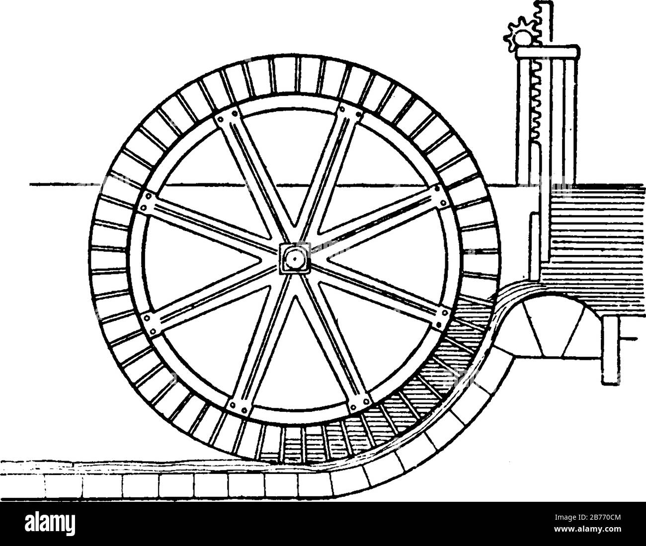
A special type of overshot/backshot wheel is the reversible water wheel. This has two sets of blades or buckets running in opposite directions so that it can turn in either direction depending on which side the water is directed. Reversible wheels were used in the mining industry in order to power various means of ore conveyance. By changing the direction of the wheel, barrels or baskets of ore could be lifted up or lowered down a shaft or inclined plane. There was usually a cable drum or a chain basket on the axle of the wheel. It is essential that the wheel have braking equipment to be able to stop the wheel (known as a braking wheel). The oldest known drawing of a reversible water wheel was by Georgius Agricola and dates to 1556.
The earliest waterwheel working like a lever was described by Zhuangzi in the late Warring States period (476-221 BC). It says that the waterwheel was invented by Zigong, a disciple of Confucius in the 5th century BC.Chinese of the Eastern Han Dynasty were using water wheels to crush grain in mills and to power the piston-bellows in forging iron ore into cast iron.
In the text known as the Xin Lun written by Huan Tan about 20 AD (during the usurpation of Wang Mang), it states that the legendary mythological king known as Fu Xi was the one responsible for the pestle and mortar, which evolved into the tilt-hammer and then trip hammer device (see trip hammer). Although the author speaks of the mythological Fu Xi, a passage of his writing gives hint that the water wheel was in widespread use by the 1st century AD in China (Wade-Giles spelling):
In the year 31 AD, the engineer and Prefect of Nanyang, Du Shi (d. 38), applied a complex use of the water wheel and machinery to power the bellows of the blast furnace to create cast iron. Du Shi is mentioned briefly in the Hou Han Shu) as follows (in Wade-Giles spelling):
Water wheels in China found practical uses such as this, as well as extraordinary use. The Chinese inventor Zhang Heng (78–139) was the first in history to apply motive power in rotating the astronomical instrument of an armillary sphere, by use of a water wheel.mechanical engineer Ma Jun (c. 200–265) from Cao Wei once used a water wheel to power and operate a large mechanical puppet theater for the Emperor Ming of Wei (r. 226–239).
The ancient Greeks invented the waterwheel independently and used it in nearly all of the forms and functions described above, including its application for watermilling.Hellenistic period between the 3rd and 1st century BC.
The compartmented water wheel comes in two basic forms, the wheel with compartmented body (Latin tympanum) and the wheel with compartmented rim or a rim with separate, attached containers.sakia gear.
The earliest literary reference to a water-driven, compartmented wheel appears in the technical treatise Pneumatica (chap. 61) of the Greek engineer Philo of Byzantium (ca. 280−220 BC).Parasceuastica (91.43−44), Philo advises the use of such wheels for submerging siege mines as a defensive measure against enemy sapping.dry docks in Alexandria under the reign of Ptolemy IV (221−205 BC).papyri of the 3rd to 2nd century BC mention the use of these wheels, but don"t give further details.Ancient Near East before Alexander"s conquest can be deduced from its pronounced absence from the otherwise rich oriental iconography on irrigation practices.
The earliest depiction of a compartmented wheel is from a tomb painting in Ptolemaic Egypt which dates to the 2nd century BC. It shows a pair of yoked oxen driving the wheel via a sakia gear, which is here for the first time attested, too.Museum of Alexandria, at the time the most active Greek research center, may have been involved in its invention.Alexandrian War in 48 BC tells of how Caesar"s enemies employed geared waterwheels to pour sea water from elevated places on the position of the trapped Romans.
Around 300 AD, the noria was finally introduced when the wooden compartments were replaced with inexpensive ceramic pots that were tied to the outside of an open-framed wheel.
The Romans used waterwheels extensively in mining projects, with enormous Roman-era waterwheels found in places like modern-day Spain. They were reverse overshot water-wheels designed for dewatering deep underground mines.Vitruvius, including the reverse overshot water-wheel and the Archimedean screw. Many were found during modern mining at the copper mines at Rio Tinto in Spain, one system involving 16 such wheels stacked above one another so as to lift water about 80 feet from the mine sump. Part of such a wheel was found at Dolaucothi, a Roman gold mine in south Wales in the 1930s when the mine was briefly re-opened. It was found about 160 feet below the surface, so must have been part of a similar sequence as that discovered at Rio Tinto. It has recently been carbon dated to about 90 AD, and since the wood from which it was made is much older than the deep mine, it is likely that the deep workings were in operation perhaps 30–50 years after. It is clear from these examples of drainage wheels found in sealed underground galleries in widely separated locations that building water wheels was well within their capabilities, and such verticals water wheels commonly used for industrial purposes.
About the same time, the overshot wheel appears for the first time in a poem by Antipater of Thessalonica, which praises it as a labour-saving device (IX, 418.4–6).Lucretius (ca. 99–55 BC) who likens the rotation of the waterwheel to the motion of the stars on the firmament (V 516).central Gaul.Barbegal watermill complex a series of sixteen overshot wheels was fed by an artificial aqueduct, a proto-industrial grain factory which has been referred to as "the greatest known concentration of mechanical power in the ancient world".
In Roman North Africa, several installations from around 300 AD were found where vertical-axle waterwheels fitted with angled blades were installed at the bottom of a water-filled, circular shaft. The water from the mill-race which entered tangentially the pit created a swirling water column that made the fully submerged wheel act like true water turbines, the earliest known to date.
Apart from its use in milling and water-raising, ancient engineers applied the paddled waterwheel for automatons and in navigation. Vitruvius (X 9.5–7) describes multi-geared paddle wheels working as a ship odometer, the earliest of its kind. The first mention of paddle wheels as a means of propulsion comes from the 4th–5th century military treatise
Ancient water-wheel technology continued unabated in the early medieval period where the appearance of new documentary genres such as legal codes, monastic charters, but also hagiography was accompanied with a sharp increase in references to watermills and wheels.
The earliest excavated water wheel driven by tidal power was the Nendrum Monastery mill in Northern Ireland which has been dated to 787, although a possible earlier mill dates to 619. Tide mills became common in estuaries with a good tidal range in both Europe and America generally using undershot wheels.
Cistercian monasteries, in particular, made extensive use of water wheels to power watermills of many kinds. An early example of a very large water wheel is the still extant wheel at the early 13th century Real Monasterio de Nuestra Senora de Rueda, a Cistercian monastery in the Aragon region of Spain. Grist mills (for corn) were undoubtedly the most common, but there were also sawmills, fulling mills and mills to fulfil many other labour-intensive tasks. The water wheel remained competitive with the steam engine well into the Industrial Revolution. At around the 8th to 10th century, a number of irrigation technologies were brought into Spain and thus introduced to Europe. One of those technologies is the Noria, which is basically a wheel fitted with buckets on the peripherals for lifting water. It is similar to the undershot water wheel mentioned later in this article. It allowed peasants to power watermills more efficiently. According to Thomas Glick"s book, Irrigation and Society in Medieval Valencia, the Noria probably originated from somewhere in Persia. It has been used for centuries before the technology was brought into Spain by Arabs who had adopted it from the Romans. Thus the distribution of the Noria in the Iberian peninsula "conforms to the area of stabilized Islamic settlement".Spaniards, the technology spread to the New World in Mexico and South America following Spanish expansion
The type of water wheel selected was dependent upon the location. Generally if only small volumes of water and high waterfalls were available a millwright would choose to use an overshot wheel. The decision was influenced by the fact that the buckets could catch and use even a small volume of water.
Harnessing water-power enabled gains in agricultural productivity, food surpluses and the large scale urbanization starting in the 11th century. The usefulness of water power motivated European experiments with other power sources, such as wind and tidal mills.canals, put Europe on a hydraulically focused path, for instance water supply and irrigation technology was combined to modify supply power of the wheel.feudal state.
The water mill was used for grinding grain, producing flour for bread, malt for beer, or coarse meal for porridge.fulling mill, which was used for cloth making. The trip hammer was also used for making wrought iron and for working iron into useful shapes, an activity that was otherwise labour-intensive. The water wheel was also used in papermaking, beating material to a pulp. In the 13th century water mills used for hammering throughout Europe improved the productivity of early steel manufacturing. Along with the mastery of gunpowder, waterpower provided European countries worldwide military leadership from the 15th century.
Millwrights distinguished between the two forces, impulse and weight, at work in water wheels long before 18th-century Europe. Fitzherbert, a 16th-century agricultural writer, wrote "druieth the wheel as well as with the weight of the water as with strengthe [impulse]".Leonardo da Vinci also discussed water power, noting "the blow [of the water] is not weight, but excites a power of weight, almost equal to its own power".laws of force. Evangelista Torricelli"s work on water wheels used an analysis of Galileo"s work on falling bodies, that the velocity of a water sprouting from an orifice under its head was exactly equivalent to the velocity a drop of water acquired in falling freely from the same height.
The water wheel was a driving force behind the earliest stages of industrialization in Britain. Water-powered reciprocating devices were used in trip hammers and blast furnace bellows. Richard Arkwright"s water frame was powered by a water wheel.
The most powerful water wheel built in the United Kingdom was the 100 hp Quarry Bank Mill water wheel near Manchester. A high breastshot design, it was retired in 1904 and replaced with several turbines. It has now been restored and is a museum open to the public.
The biggest working water wheel in mainland Britain has a diameter of 15.4 m (51 ft) and was built by the De Winton company of Caernarfon. It is located within the Dinorwic workshops of the National Slate Museum in Llanberis, North Wales.
The largest working water wheel in the world is the Laxey Wheel (also known as Lady Isabella) in the village of Laxey, Isle of Man. It is 72 feet 6 inches (22.10 m) in diameter and 6 feet (1.83 m) wide and is maintained by Manx National Heritage.
During the Industrial Revolution, in the first half of the 19th century engineers started to design better wheels. In 1823 Jean-Victor Poncelet invented a very efficient undershot wheel design that could work on very low heads, which was commercialized and became popular by late 1830s. Other designs, as the Sagebien wheel, followed later. At the same time Claude Burdin was working on a radically different machine which he called turbine, and his pupil Benoît Fourneyron designed the first commercial one in the 1830s.
Development of water turbines led to decreased popularity of water wheels. The main advantage of turbines is that its ability to harness head is much greater than the diameter of the turbine, whereas a water wheel cannot effectively harness head greater than its diameter. The migration from water wheels to modern turbines took about one hundred years.
Water wheels were used to power sawmills, grist mills and for other purposes during development of the United States. The 40 feet (12 m) diameter water wheel at McCoy, Colorado, built in 1922, is a surviving one out of many which lifted water for irrigation out of the Colorado River.
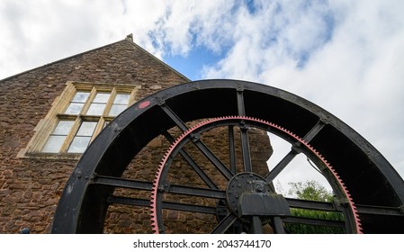
Two early improvements were suspension wheels and rim gearing. Suspension wheels are constructed in the same manner as a bicycle wheel, the rim being supported under tension from the hub- this led to larger lighter wheels than the former design where the heavy spokes were under compression. Rim-gearing entailed adding a notched wheel to the rim or shroud of the wheel. A stub gear engaged the rim-gear and took the power into the mill using an independent line shaft. This removed the rotative stress from the axle which could thus be lighter, and also allowed more flexibility in the location of the power train. The shaft rotation was geared up from that of the wheel which led to less power loss. An example of this design pioneered by Thomas Hewes and refined by William Armstrong Fairburn can be seen at the 1849 restored wheel at the Portland Basin Canal Warehouse.
Australia has a relatively dry climate, nonetheless, where suitable water resources were available, water wheels were constructed in 19th-century Australia. These were used to power sawmills, flour mills, and stamper batteries used to crush gold-bearing ore. Notable examples of water wheels used in gold recovery operations were the large Garfield water wheel near Chewton—one of at least seven water wheels in the surrounding area—and the two water wheels at Adelong Falls; some remnants exist at both sites.Walhalla once had at least two water wheels, one of which was rolled to its site from Port Albert, on its rim using a novel trolley arrangement, taking nearly 90 days.water wheel at Jindabyne, constructed in 1847, was the first machine used to extract energy—for flour milling—from the Snowy River.
The early history of the watermill in India is obscure. Ancient Indian texts dating back to the 4th century BC refer to the term cakkavattaka (turning wheel), which commentaries explain as arahatta-ghati-yanta (machine with wheel-pots attached). On this basis, Joseph Needham suggested that the machine was a noria. Terry S. Reynolds, however, argues that the "term used in Indian texts is ambiguous and does not clearly indicate a water-powered device." Thorkild Schiøler argued that it is "more likely that these passages refer to some type of tread- or hand-operated water-lifting device, instead of a water-powered water-lifting wheel."
Around 1150, the astronomer Bhaskara Achārya observed water-raising wheels and imagined such a wheel lifting enough water to replenish the stream driving it, effectively, a perpetual motion machine.Arabic and Persian works. During medieval times, the diffusion of Indian and Persian irrigation technologies gave rise to an advanced irrigation system which bought about economic growth and also helped in the growth of material culture.
After the spread of Islam engineers of the Islamic world continued the water technologies of the ancient Near East; as evident in the excavation of a canal in the Basra region with remains of a water wheel dating from the 7th century. Hama in Syria still preserves some of its large wheels, on the river Orontes, although they are no longer in use.Murcia in Spain, La Nora, and although the original wheel has been replaced by a steel one, the Moorish system during al-Andalus is otherwise virtually unchanged. Some medieval Islamic compartmented water wheels could lift water as high as 30 metres (100 ft).Muhammad ibn Zakariya al-Razi"s Kitab al-Hawi in the 10th century described a noria in Iraq that could lift as much as 153,000 litres per hour (34,000 imp gal/h), or 2,550 litres per minute (560 imp gal/min). This is comparable to the output of modern norias in East Asia, which can lift up to 288,000 litres per hour (63,000 imp gal/h), or 4,800 litres per minute (1,100 imp gal/min).
The industrial uses of watermills in the Islamic world date back to the 7th century, while horizontal-wheeled and vertical-wheeled water mills were both in widespread use by the 9th century. A variety of industrial watermills were used in the Islamic world, including gristmills, hullers, sawmills, shipmills, stamp mills, steel mills, sugar mills, and tide mills. By the 11th century, every province throughout the Islamic world had these industrial watermills in operation, from al-Andalus and North Africa to the Middle East and Central Asia.crankshafts and water turbines, gears in watermills and water-raising machines, and dams as a source of water, used to provide additional power to watermills and water-raising machines.factory complexes built in al-Andalus between the 11th and 13th centuries.
The engineers of the Islamic world developed several solutions to achieve the maximum output from a water wheel. One solution was to mount them to piers of bridges to take advantage of the increased flow. Another solution was the shipmill, a type of water mill powered by water wheels mounted on the sides of ships moored in midstream. This technique was employed along the Tigris and Euphrates rivers in 10th-century Iraq, where large shipmills made of teak and iron could produce 10 tons of flour from corn every day for the granary in Baghdad.flywheel mechanism, which is used to smooth out the delivery of power from a driving device to a driven machine, was invented by Ibn Bassal (fl. 1038–1075) of Al-Andalus; he pioneered the use of the flywheel in the saqiya (chain pump) and noria.Al-Jazari in the 13th century and Taqi al-Din in the 16th century described many inventive water-raising machines in their technological treatises. They also employed water wheels to power a variety of devices, including various water clocks and automata.
A recent development of the breastshot wheel is a hydraulic wheel which effectively incorporates automatic regulation systems. The Aqualienne is one example. It generates between 37 kW and 200 kW of electricity from a 20 m3 (710 cu ft) waterflow with a head of 1 to 3.5 m (3 to 11 ft).
Overshot (and particularly backshot) wheels are the most efficient type; a backshot steel wheel can be more efficient (about 60%) than all but the most advanced and well-constructed turbines. In some situations an overshot wheel is preferable to a turbine.
The development of the hydraulic turbine wheels with their improved efficiency (>67%) opened up an alternative path for the installation of water wheels in existing mills, or redevelopment of abandoned mills.
The kinetic energy can be accounted for by converting it into an equivalent head, the velocity head, and adding it to the actual head. For still water the velocity head is zero, and to a good approximation it is negligible for slowly moving water, and can be ignored. The velocity in the tail race is not taken into account because for a perfect wheel the water would leave with zero energy which requires zero velocity. That is impossible, the water has to move away from the wheel, and represents an unavoidable cause of inefficiency.
The power is how fast that energy is delivered which is determined by the flow rate. It has been estimated that the ancient donkey or slave-powered quern of Rome made about one-half of a horsepower, the horizontal waterwheel creating slightly more than one-half of a horsepower, the undershot vertical waterwheel produced about three horsepower, and the medieval overshot waterwheel produced up to forty to sixty horsepower.
From the cross sectional area and the velocity. They must be measured at the same place but that can be anywhere in the head or tail races. It must have the same amount of water going through it as the wheel.
A parallel development is the hydraulic wheel/part reaction turbine that also incorporates a weir into the centre of the wheel but uses blades angled to the water flow.
The University of Southampton School of Civil Engineering and the Environment in the UK has investigated both types of Hydraulic wheel machines and has estimated their hydraulic efficiency and suggested improvements, i.e. The Rotary Hydraulic Pressure Machine. (Estimated maximum efficiency 85%).
These type of water wheels have high efficiency at part loads / variable flows and can operate at very low heads, < 1 m (3 ft 3 in). Combined with direct drive Axial Flux Permanent Magnet Alternators and power electronics they offer a viable alternative for low head hydroelectric power generation.
The Editors of Encyclopædia Britannica. "Waterwheel". Britannica.com. Encyclopædia Britannica, Inc. Retrieved 19 January 2018. |last1= has generic name (help)
Müller, G.; Wolter, C. (2004). "The breastshot waterwheel: design and model tests" (PDF). Proceedings of the Institution of Civil Engineers - Engineering Sustainability. 157 (4): 203–211. doi:10.1680/ensu.2004.157.4.203. ISSN 1478-4629 – via Semantic Scholar.
Wikander 2000, p. 395; Oleson 2000, p. 229It is no surprise that all the water-lifting devices that depend on subdivided wheels or cylinders originate in the sophisticated, scientifically advanced Hellenistic period, ...
Oleson 2000, pp. 235: The sudden appearance of literary and archaological evidence for the compartmented wheel in the third century B.C. stand in marked contrast to the complete absence of earlier testimony, suggesting that the device was invented not long before.
An isolated passage in the Hebrew Deuteronomy (11.10−11) about Egypt as a country where you sowed your seed and watered it with your feet is interpreted as an metaphor referring to the digging of irrigation channels rather than treading a waterwheel (Oleson 2000, pp. 234).
As for a Mesopotamian connection: Schioler 1973, p. 165−167: References to water-wheels in ancient Mesopotamia, found in handbooks and popular accounts, are for the most part based on the false assumption that the Akkadian equivalent of the logogram GIS.APIN was nartabu and denotes an instrument for watering ("instrument for making moist").As a result of his investigations, Laessoe writes as follows on the question of the saqiya: "I consider it unlikely that any reference to the saqiya will appear in ancient Mesopotamian sources." In his opinion, we should turn our attention to Alexandria, "where it seems plausible to assume that the saqiya was invented."
Adriana de Miranda (2007), Water architecture in the lands of Syria: the water-wheels, L"Erma di Bretschneider, pp. 48f, ISBN 978-8882654337 concludes that the Akkadian passages "are counched in terms too general too allow any conclusion as to the excat structure" of the irrigation apparatus, and states that "the latest official Chicago Assyrian Dictionary reports meanings not related to types of irrigation system".
Terry S, Reynolds, Stronger than a Hundred Men; A History of the Vertical Water Wheel. Baltimore; Johns Hopkins University Press, 1983. Robert, Friedel, A Culture of Improvement. MIT Press. Cambridge, Massachusetts. London, England. (2007). p. 33.
Davies, Peter; Lawrence, Susan (2013). "The Garfield water wheel: hydraulic power on the Victorian goldfields" (PDF). Australasian Historical Archaeology. 31: 25–32.
Gies, Frances; Gies, Joseph (1994). Cathedral, Forge, and Waterwheel: Technology and Invention in the Middle Ages. HarperCollins Publishers. p. 115. ISBN 0060165901.
Quaranta Emanuele, Revelli Roberto (2015), "Performance characteristics, power losses and mechanical power estimation for a breastshot water wheel", Energy, Energy, Elsevier, 87: 315–325, doi:10.1016/j.energy.2015.04.079
Reynolds, T.S. (1983) Stronger Than a Hundred Men: A History of the Vertical Water Wheel, Johns Hopkins studies in the history of technology: New Series 7, Baltimore: Johns Hopkins University Press, ISBN 0-8018-2554-7
Wilson, Andrew (1995), "Water-Power in North Africa and the Development of the Horizontal Water-Wheel", Journal of Roman Archaeology, vol. 8, pp. 499–510
(For good background information for this article, the reader should read “Waterpower for personal use” in Issue No. 16 and “Design calculations for overshot waterwheels” in Issue No. 17. — Editor)
This is the type most familiar to people where the water is introduced to the top of the wheel by a chute, known as a flume. In spite of the public impression that these machines are low technology, they were actually quite extensively studied by academicians. The first to study them was a Roman named Vetruvius, who wrote what is considered to be the earliest known engineering treatise. The work on waterwheels by Lazare Carnot’ in the early 1700s not only advanced fluid dynamics, but his study was the groundwork for the study of thermodynamics.
As we discussed in previous articles (Issues No. 16 and 17), the most important thing to determine when utilizing a waterwheel is “head”, or how far the water falls. This is important because it has a lot to do with the diameter of the wheel. Ideally, the wheel diameter should should be 90% of the “head”. For convenience we choose some even number, in feet, that is nearly 90%. Unless the wheel is unusually large, we choose a diameter equal to the “head” minus two feet. This two-foot difference will be the depth of our flume.
But how fast will it turn? The most efficient energy transfer occurs when the wheel speed is at 93% of the water speed. For our example, the spouting velocity is 11.35 feet per second. So 93% of that is around 10 feet per second, which is the same as 600 feet-per-minute. You divide this by the working circumference per revolution. This gives you an answer of 19 revolutions per minute. That is your best rotative speed.
The power you will get depends on the width. For our example, let’s assume you have a design flow of 50 cfs (cubic feet per second). When you divide this by the design speed of 10 feet per second, you see you need a bucket area of 5 square feet. If our buckets are 1 foot deep, the wheel should be 5 feet wide, “plus” one foot extra on each side to ventilate the buckets. As the water comes in, the air “must” get out.
One important detail: Put a one-inch diameter hole near the bottom of each bucket. This is to prevent them from sucking air when they are submerged. That can use up half of your power, while only a negligible amount of water leaks out. As I said last issue, power is equal to “flow” times “head” divided by 11.8. Therefore, we have a “flow” of 50 cfs “times” a “head” of 12′ divided by 11.8. 50 X 12 = 600. 600/11.8 = 50.8 kilowatts. To state it another way, 50.8 kilowatts/.746 gives you 68 horsepower. We should assume an efficiency of 90%, so our hypothetical wheel will produce 61 horsepower or 45 kilowatts.
These calculations apply to “any” overshot waterwheel. The only thing that changes among the various designs is the speed or dimensions. Materials should always be a good grade of steel. A36 or B36 works very well. 20 gauge or thicker is good. We always use 1/8″ and ours have withstood direct hits by ice flows of more than a ton. If you use “corten”, a weathering steel, it will not need painting and will acquire a reddish color that resembles wood.
Staticly balance the wheel before installation. No matter how tempting, never use wood. It rots and holds water unevenly. This unbalances the wheel and makes it unsuitable for any use except grinding grain. Be very accurate in all your measurements, especially those concerning “flow” and “head”. If they are wrong, everything is wrong.
I recommend oil-impregnated wood bearing. They can be obtained from the POBCO Bearing Company of Worcester, MA. Waterwheels turn too slowly for ball or sleeve bearings. They cannot maintain a uniform lubricant field. This tends to ruin the bearing quickly. The wood bearings have a “wick” action that maintains uniform lubricant.

(This introductory overview to waterwheels is the first of a three-part series. The second installment [Issue No.17] will be about undershot and no-head wheels, and the third installment [Issue No. 18] will deal with overshot wheels. Editor)
The creak of an old, wooden moss-covered wheel lazily driving a gristmill in a long lost past is how most people think of a small scale water power. Of course water power is old. Historical records put it at around 4000 years old. While that makes it an ancient technology, that doesn’t make it an antique technology. If you have ever considered windmills, think of a water wheel as a windmill that uses a fluid 824 times as dense. In other words, 824 times as powerful. On the negative side, you need access to a good stream, while the wind is everywhere. I am making this comparison to show that water power isn’t any more complicated than wind power to understand.
Waterwheels run because “gravity” causes a “mass” of water to fall some distance (HEAD). This energy is absorbed by the wheel to do work. There is more than one way to absorb the energy, so wheels have evolved into two classes:
For this reason I recommendimpulse type water wheels. These function by transferring the momentum of the moving water to the machine. The energy transfer is similar to one billiard ball transferring its energy to another. Because of this, impulse wheels have a very high efficiency, and more importantly, have a constant efficiency over varying stream conditions.
On a small, variable stream (a typical home/farm stream) an impulse wheel can produce more than twice the kilowatt hours of a reaction wheel. Impulse wheels are available in several types, each designed for a specific type of stream.
A FITZ C-Rotor and the Scheider Lift Translator are autonomous generators, containing the wheel, generator, and regulator in a single unit. You just place one in a stream and connect the power cable to a load. Both designs are quite cost-effective as a personal power source.
Undershot wheels range from simple paddle wheels placed in a stream to Poncelot Wheels. They were developed in France during the 18th century. They are good for small to medium flows and heads from 1 foot to 12 feet. If properly designed, a Poncelot can be 85% efficient or more. Even an amateur-built wheel can be over 75% efficient.
Overshot wheels are the kind people associate with Currier & Ives engravings. While many were made of wood, after 1840 most were made of metal. For small streams and heads up to 25 feet, these are still the best choice for a home/farm user. The old FITZ I-X-L designed in 1862 was tested at the University of Wisconsin in 1913. It proved to be 93% efficient.
Crossflow turbines are incorrectly called a turbine since they work on the impulse principal. They can best be described as undershot wheels in a can. They are useful for small to large flows and heads from 10 feet to 100 feet. They are close tolerance devices so we wouldn’t recommend this design to an amateur builder unless you have some machining experience. A Pelton wheel is a high head variant of the crossflow, best used with heads of 50 feet or higher.
Surprisingly, wheel horsepower and efficiency are not the most important factors. This is because stream flows vary over the year. The best choice is the wheel that delivers 50% or more of the theoretical power of the stream. In other words, the total annual production should be at least HALF of the production you would get if the wheel ran at full power all year long.
For example, there are 8760 hours in a year. If you had a 100 kilowatt wheel, it should produce 438,000 kilowatt-hours annually. (100 KW * 8760 * 50%). If it doesn’t, you should use a smaller wheel. This isn’t as difficult to calculate as it sounds. Power available can be calculated as flow (in cubic feet per second) times head (in feet) divided by 11.8. This will give you power in kilowatts. Divide this answer by 0.746 to get horsepower.
Also remember a stream varies over the year. The most important thing to know for any waterwheel installation is how much water is available, and how much can you use. An oversized wheel is both inefficient and a waste of money. Plot the flows if you can, or get stream flow data from the U.S. Geological Survey. Usually a flow that is met or exceeded 25% of the time is a good flow to size your generator. While you may miss some power during spring floods, remember that they don’t occur often enough to justify the expense of a larger waterwheel.
When selecting a generator type, decide if you want AC or DC power. Will you co-generate with the electric company or go it alone? If your power plant is 25 kilowatts or larger, a self regulated AC system is the best. If it is smaller, or you want to supplement with wind power or photovoltaics, DC is the simplest to use. If you are co-generating, a simple AC induction system will work for any size power plant. This is the absolute least cost arrangement. Here is where the self-regulating characteristics of impulse wheels really pay off.
Impulse wheels turn slowly. This was one reason reaction turbines were invented. Today gearing is very reliable so it is no longer necessary to direct drive a generator. This also allows use of more efficient 4-pole (1800 rpm) generators. Any industrial enclosed drive will work. Do not use auto transmissions. They were never intended for continuous duty. The bearings and casing are too light unless you are making 10 kilowatts or less.
This is an overview of how waterwheels can be used for personal power plants. As in anything, attention to detail is what separates success from failure. Measure your stream carefully, and don’t over-estimate your power needs or building skills. Waterwheels are heavy industrial machines.
On the other hand, don’t under-estimate what one person looking to change their piece of the world can do. Before I bought the FITZ Waterwheel company, I had been through some hard times. Now 6 years later, I operate 1250 kilowatts of generators commercially, providing clean, environmentally safe power to over 1000 homes. I hope you have as much fun and satisfaction with your waterwheel, whatever the size.
Water wheel design has evolved over time with some water wheels oriented vertically, some horizontally and some with elaborate pulleys and gears attached, but they are all designed to do the same function and that is too, “convert the linear motion of the moving water into a rotary motion which can be used to drive any piece of machinery connected to it via a rotating shaft”.
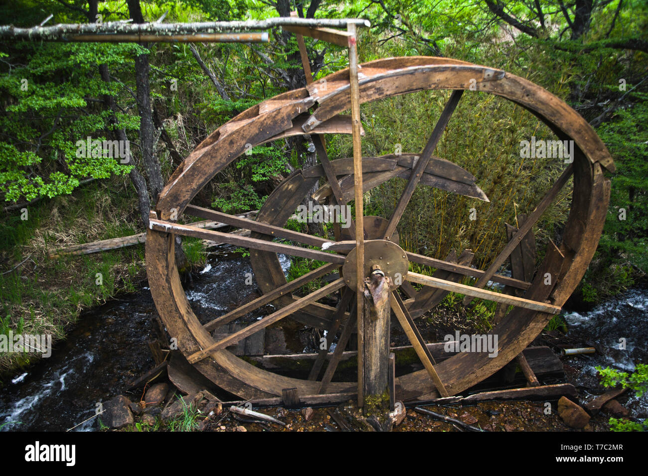
Early Waterwheel Design were quite primitive and simple machines consisting of a vertical wooden wheel with wooden blades or buckets fixed equally around their circumference all supported on a horizontal shaft with the force of the water flowing underneath it pushing the wheel in a tangential direction against the blades.
These vertical waterwheels were vastly superior to the earlier horizontal waterwheel design by the ancient Greeks and Egyptians, because they could operate more efficiently translating the hydrokinetic energy of the moving water into mechanical power. Pulleys and gearing was then attached to the waterwheel which allowed a change in direction of a rotating shaft from horizontal to vertical in order to operate millstones, saw wood, crush ore, stamping and cutting etc.
Most Waterwheels also known as Watermills or simply Water Wheels, are vertically mounted wheels rotating about a horizontal axle, and these types of waterwheels are classified by the way in which the water is applied to the wheel, relative to the wheel’s axle. As you may expect, waterwheels are relatively large machines which rotate at low angular speeds, and have a low efficiency, due to losses by friction and the incomplete filling of the buckets, etc.
The action of the water pushing against the wheels buckets or paddles develops torque on the axle but by directing the water at these paddles and buckets from different positions on the wheel the speed of rotation and its efficiency can be improved. The two most common types of waterwheel design is the “undershot waterwheel” and the “overshot waterwheel”.
The Undershot Water Wheel Design, also known as a “stream wheel” was the most commonly used type of waterwheel designed by the ancient Greeks and Romans as it is the simplest, cheapest and easiest type of wheel to construct.
In this type of waterwheel design, the wheel is simply placed directly into a fast flowing river and supported from above. The motion of the water below creates a pushing action against the submerged paddles on the lower part of the wheel allowing it to rotate in one direction only relative to the direction of the flow of the water.
This type of waterwheel design is generally used in flat areas with no natural slope of the land or where the flow of water is sufficiently fast moving. Compared with the other waterwheel designs, this type of design is very inefficient, with as little as 20% of the waters potential energy being used to actually rotate the wheel. Also the waters energy is used only once to rotate the wheel, after which it flows away with the rest of the water.
Another disadvantage of the undershot water wheel is that it requires large quantities of water moving at speed. Therefore, undershot waterwheels are usually situated on the banks of rivers as smaller streams or brooks do not have enough potential energy in the moving water.
One way of improving the efficiency slightly of an undershot waterwheel is to divert a percentage off the water in the river along a narrow channel or duct so that 100% of the diverted water is used to rotate the wheel. In order to achieve this the undershot wheel has to be narrow and fit very accurately within the channel to prevent the water from escaping around the sides or by increasing either the number or size of the paddles.
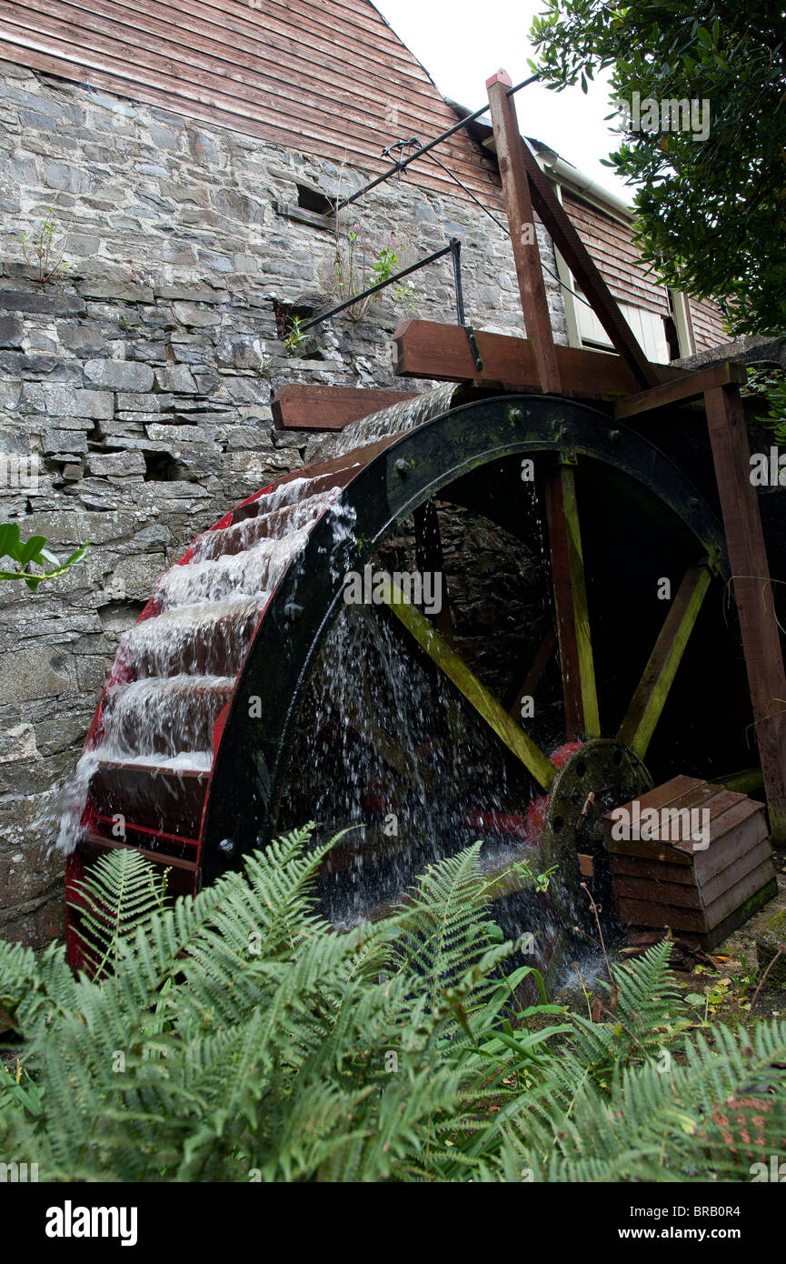
The Overshot Water Wheel Design is the most common type of waterwheel design. The overshot waterwheel is more complicated in its construction and design than the previous undershot waterwheel as it uses buckets or small compartments to both catch and hold the water.
These buckets fill with water flowing onto the wheel through a penstock design above. The gravitational weight of the water in the full buckets causes the wheel to rotate around its central axis as the empty buckets on the other side of the wheel become lighter.
This type of water wheel uses gravity to improve output as well as the water itself, thus overshot waterwheels are much more efficient than undershot designs as almost all of the water and its weight is being used to produce output power. However as before, the waters energy is used only once to rotate the wheel, after which it flows away with the rest of the water.
Overshot waterwheels are suspended above a river or stream and are generally built on the sides of hills providing a water supply from above with a low head (the vertical distance between the water at the top and the river or stream below) of between 5-to-20 metres. A small dam or weir can be constructed and used to both channel and increase the speed of the water to the top of the wheel giving it more energy but it is the volume of water rather than its speed which helps rotate the wheel.
Generally, overshot waterwheels are built as large as possible to give the greatest possible head distance for the gravitational weight of the water to rotate the wheel. However, large diameter waterwheels are more complicated and expensive to construct due to the weight of the wheel and water.
When the individual buckets are filled with water, the gravitational weight of the water causes the wheel to rotate in the direction of the flow of water. As the angle of rotation gets nearer to the bottom of the wheel, the water inside the bucket empties out into the river or stream below, but the weight of the buckets rotating behind it causes the wheel to continue with its rotational speed.
Once the bucket is empty of water it continues around the rotating wheel until it gets back up to the top again ready to be filled with more water and the cycle repeats. One of the disadvantages of an overshot waterwheel design is that the water is only used once as it flows over the wheel.
The Pitchback Water Wheel Design is a variation on the previous overshot waterwheel as it also uses the gravitational weight of the water to help rotate the wheel, but it also uses the flow of the waste water below it to give an extra push. This type of waterwheel design uses a low head infeed system which provides the water near to the top of the wheel from a pentrough above.
Unlike the overshot waterwheel which channelled the water directly over the wheel causing it to rotate in the direction of the flow of the water, the pitchback waterwheel feeds the water vertically downwards through a funnel and into the bucket below causing the wheel to rotate in the opposite direction to the flow of the water above.
Just like the previous overshot waterwheel, the gravitational weight of the water in the buckets causes the wheel to rotate but in an anti-clockwise direction. As the angle of rotation nears the bottom of the wheel, the water trapped inside the buckets empties out below. As the empty bucket is attached to the wheel, it continues rotating with the wheel as before until it gets back up to the top again ready to be filled with more water and the cycle repeats.
The difference this time is that the waste water emptied out of the rotating bucket flows away in the direction of the rotating wheel (as it has nowhere else to go), similar to the undershot waterwheel principal. Thus the main advantage of the pitchback waterwheel is that it uses the energy of the water twice, once from above and once from below to rotate the wheel around its central axis.
The result is that the efficiency of the waterwheel design is greatly increased to over 80% of the waters energy as it is driven by both the gravitaional weight of the incoming water and by the force or pressure of water directed into the buckets from above, as well as the flow of the waste water below pushing against the buckets. The disadvantage though of an pitchback waterwheel is that it needs a slightly more complex water supply arrangement directly above the wheel with chutes and pentrough


 8613371530291