
reverse overshot water wheel made in china

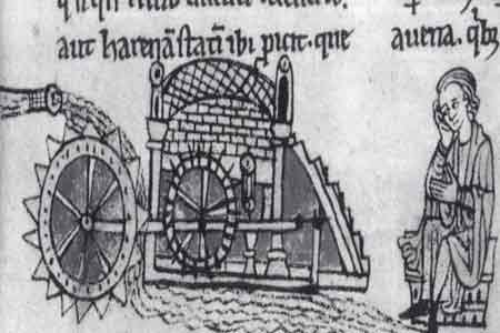
Frequently used in mines and probably elsewhere (such as agricultural drainage), the reverse overshot water wheel was a Roman innovation to help remove water from the lowest levels of underground workings. It is described by Vitruvius in his work
The Roman author Vitruvius gives explicit instructions on the construction of dewatering devices, and describes three variants of the "tympanum" in Chapter X of
Pliny the Elder is probably referring to such devices in a discussion of silver/lead mines in his silver in his time, many of the silver mines having been started by Hannibal. One of the largest had galleries running for between one and two miles into the mountain, "water-men" (in Latin "aquatini") draining the mine, and they
That they stood suggests that they operated the wheels by standing on the top to turn the cleats, and continuous working would produce a steady stream of water.
Fragments of such machines have been found in mines which were re-opened in the Victorian era in Spain, especially at Rio Tinto, where one example used no less than 16 such wheels working in pairs, each pair of wheels lifting water about 3.5 metres (11 ft), so giving a total lift of 30 metres (98 ft). The system was carefully engineered, and was worked by individuals treading slats at the side of each wheel. It is not an isolated example, because Oliver Davies mentions examples from the Tharsis copper mine and Logroño in Spain, as well as from Dacia. The gold deposits in Dacia, now modern Romania were especially rich, and worked intensively after the successful Roman invasion under Trajan. According to Oliver Davies, one such sequence discovered at Ruda in Hunedoara County in modern Romania was 75 metres (246 ft) deep. If worked like the Rio Tinto example, it would have needed at least 32 wheels.
One such wheel from Spain was rescued and part of it is now on display in the British Museum. Some of the components are numbered, suggesting that it was prefabricated above ground before assembly in the underground passages. In the 1930s, a fragment of a wooden bucket from a drainage wheel was found in deep workings at the Dolaucothi gold mine in west Wales, and is now preserved in the National Museum of Wales in Cardiff. It has been carbon dated to about 90 AD. From the depth of 50 metres (160 ft) below known open workings, it can be inferred that the drainage wheel was part of a sequence just like that found in Spain. The shape of the edge of one of the lifting buckets is almost identical with that from Spain, suggesting that a template was used to make the devices.
They were also used in series, so increasing the lift of water from the workings. However, they must have been more difficult to operate since the user had to stand on a slanting surface to turn the screw. The steeper the incline, the greater the risk of the user slipping from the top of the screw. No doubt the reverse water wheel was easier to use with a horizontal treading surface. On the other hand, the screw could be operated by a crank handle fitted to the central axle, but would be more tiring since the weight of the operator does not bear on the crank, as it does when trod from above.
Like the reverse water wheel, the cochlea was used for many other purposes apart from draining mines. Irrigation of farmland would have been the most popular application, but any activity which involved lifting water would have employed the devices.
Multiple sequences of water wheels were used elsewhere in the Roman Empire, such as the famous example at Barbegal in southern France. This system was also a stack of 16 wheels but worked like a normal overshot wheel, the wheels driving stone mills and used to grind grains. The water mills were worked from a masonry aqueduct supplying the Roman town at Arles, and the remains of the masonry mills are still visible on the ground today, unlike the underground drainage systems of the mines, which were destroyed by later mining operations. Other such sequences of mills existed on the Janiculum in Rome, but have been covered and changed by later buildings built on top of them.
A water wheel is a machine for converting the energy of flowing or falling water into useful forms of power, often in a watermill. A water wheel consists of a wheel (usually constructed from wood or metal), with a number of blades or buckets arranged on the outside rim forming the driving car. Water wheels were still in commercial use well into the 20th century but they are no longer in common use. Uses included milling flour in gristmills, grinding wood into pulp for papermaking, hammering wrought iron, machining, ore crushing and pounding fibre for use in the manufacture of cloth.
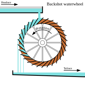
Some water wheels are fed by water from a mill pond, which is formed when a flowing stream is dammed. A channel for the water flowing to or from a water wheel is called a mill race. The race bringing water from the mill pond to the water wheel is a headrace; the one carrying water after it has left the wheel is commonly referred to as a tailrace.
Waterwheels were used for various purposes from agriculture to metallurgy in ancient civilizations spanning the Hellenistic Greek world, Rome, China and India. Waterwheels saw continued use in the Post-classical age, like the Middle Ages of Europe and the Islamic Golden Age, but also elsewhere. In the mid to late 18th century John Smeaton"s scientific investigation of the water wheel led to significant increases in efficiency supplying much needed power for the Industrial Revolution.turbine, developed by Benoît Fourneyron, beginning with his first model in 1827.elevations, that exceed the capability of practical-sized waterwheels.
The main difficulty of water wheels is their dependence on flowing water, which limits where they can be located. Modern hydroelectric dams can be viewed as the descendants of the water wheel, as they too take advantage of the movement of water downhill.
Overshot and backshot water wheels are typically used where the available height difference is more than a couple of meters. Breastshot wheels are more suited to large flows with a moderate head. Undershot and stream wheel use large flows at little or no head.
There is often an associated millpond, a reservoir for storing water and hence energy until it is needed. Larger heads store more gravitational potential energy for the same amount of water so the reservoirs for overshot and backshot wheels tend to be smaller than for breast shot wheels.
Overshot and pitchback water wheels are suitable where there is a small stream with a height difference of more than 2 metres (6.5 ft), often in association with a small reservoir. Breastshot and undershot wheels can be used on rivers or high volume flows with large reservoirs.
Stream wheels are cheaper and simpler to build and have less of an environmental impact, than other types of wheels. They do not constitute a major change of the river. Their disadvantages are their low efficiency, which means that they generate less power and can only be used where the flow rate is sufficient. A typical flat board undershot wheel uses about 20 percent of the energy in the flow of water striking the wheel as measured by English civil engineer John Smeaton in the 18th century.
Stream wheels mounted on floating platforms are often referred to as hip wheels and the mill as a ship mill. They were sometimes mounted immediately downstream from bridges where the flow restriction of the bridge piers increased the speed of the current.
An undershot wheel is a vertically mounted water wheel with a horizontal axle that is rotated by the water from a low weir striking the wheel in the bottom quarter. Most of the energy gain is from the movement of the water and comparatively little from the head. They are similar in operation and design to stream wheels.
The word breastshot is used in a variety of ways. Some authors restrict the term to wheels where the water enters at about the 10 o’clock position, others 9 o’clock, and others for a range of heights.
The small clearance between the wheel and the masonry requires that a breastshot wheel has a good trash rack ("screen" in British English) to prevent debris from jamming between the wheel and the apron and potentially causing serious damage.
Breastshot wheels are less efficient than overshot and backshot wheels but they can handle high flow rates and consequently high power. They are preferred for steady, high-volume flows such as are found on the Fall Line of the North American East Coast. Breastshot wheels are the most common type in the United States of America
A vertically mounted water wheel that is rotated by water entering buckets just past the top of the wheel is said to be overshot. The term is sometimes, erroneously, applied to backshot wheels, where the water goes down behind the wheel.
A typical overshot wheel has the water channeled to the wheel at the top and slightly beyond the axle. The water collects in the buckets on that side of the wheel, making it heavier than the other "empty" side. The weight turns the wheel, and the water flows out into the tail-water when the wheel rotates enough to invert the buckets. The overshot design is very efficient, it can achieve 90%,
Nearly all of the energy is gained from the weight of water lowered to the tailrace although a small contribution may be made by the kinetic energy of the water entering the wheel. They are suited to larger heads than the other type of wheel so they are ideally suited to hilly countries. However even the largest water wheel, the Laxey Wheel in the Isle of Man, only utilises a head of around 30 m (100 ft). The world"s largest head turbines, Bieudron Hydroelectric Power Station in Switzerland, utilise about 1,869 m (6,132 ft).
Overshot wheels require a large head compared to other types of wheel which usually means significant investment in constructing the headrace. Sometimes the final approach of the water to the wheel is along a flume or penstock, which can be lengthy.
A backshot wheel (also called pitchback) is a variety of overshot wheel where the water is introduced just before the summit of the wheel. In many situations, it has the advantage that the bottom of the wheel is moving in the same direction as the water in the tailrace which makes it more efficient. It also performs better than an overshot wheel in flood conditions when the water level may submerge the bottom of the wheel. It will continue to rotate until the water in the wheel pit rises quite high on the wheel. This makes the technique particularly suitable for streams that experience significant variations in flow and reduces the size, complexity, and hence cost of the tailrace.
The direction of rotation of a backshot wheel is the same as that of a breastshot wheel but in other respects, it is very similar to the overshot wheel. See below.
Some wheels are overshot at the top and backshot at the bottom thereby potentially combining the best features of both types. The photograph shows an example at Finch Foundry in Devon, UK. The head race is the overhead timber structure and a branch to the left supplies water to the wheel. The water exits from under the wheel back into the stream.
A special type of overshot/backshot wheel is the reversible water wheel. This has two sets of blades or buckets running in opposite directions so that it can turn in either direction depending on which side the water is directed. Reversible wheels were used in the mining industry in order to power various means of ore conveyance. By changing the direction of the wheel, barrels or baskets of ore could be lifted up or lowered down a shaft or inclined plane. There was usually a cable drum or a chain basket on the axle of the wheel. It is essential that the wheel have braking equipment to be able to stop the wheel (known as a braking wheel). The oldest known drawing of a reversible water wheel was by Georgius Agricola and dates to 1556.
The earliest waterwheel working like a lever was described by Zhuangzi in the late Warring States period (476-221 BC). It says that the waterwheel was invented by Zigong, a disciple of Confucius in the 5th century BC.Chinese of the Eastern Han Dynasty were using water wheels to crush grain in mills and to power the piston-bellows in forging iron ore into cast iron.
In the text known as the Xin Lun written by Huan Tan about 20 AD (during the usurpation of Wang Mang), it states that the legendary mythological king known as Fu Xi was the one responsible for the pestle and mortar, which evolved into the tilt-hammer and then trip hammer device (see trip hammer). Although the author speaks of the mythological Fu Xi, a passage of his writing gives hint that the water wheel was in widespread use by the 1st century AD in China (Wade-Giles spelling):
Fu Hsi invented the pestle and mortar, which is so useful, and later on it was cleverly improved in such a way that the whole weight of the body could be used for treading on the tilt-hammer (tui), thus increasing the efficiency ten times. Afterwards the power of animals—donkeys, mules, oxen, and horses—was applied by means of machinery, and water-power too used for pounding, so that the benefit was increased a hundredfold.
In the year 31 AD, the engineer and Prefect of Nanyang, Du Shi (d. 38), applied a complex use of the water wheel and machinery to power the bellows of the blast furnace to create cast iron. Du Shi is mentioned briefly in the Hou Han Shu) as follows (in Wade-Giles spelling):
In the seventh year of the Chien-Wu reign period (31 AD) Tu Shih was posted to be Prefect of Nanyang. He was a generous man and his policies were peaceful; he destroyed evil-doers and established the dignity (of his office). Good at planning, he loved the common people and wished to save their labor. He invented a water-power reciprocator (shui phai) for the casting of (iron) agricultural implements. Those who smelted and cast already had the push-bellows to blow up their charcoal fires, and now they were instructed to use the rushing of the water (chi shui) to operate it ... Thus the people got great benefit for little labor. They found the "water(-powered) bellows" convenient and adopted it widely.
Water wheels in China found practical uses such as this, as well as extraordinary use. The Chinese inventor Zhang Heng (78–139) was the first in history to apply motive power in rotating the astronomical instrument of an armillary sphere, by use of a water wheel.mechanical engineer Ma Jun (c. 200–265) from Cao Wei once used a water wheel to power and operate a large mechanical puppet theater for the Emperor Ming of Wei (r. 226–239).
The ancient Greeks invented the waterwheel independently and used it in nearly all of the forms and functions described above, including its application for watermilling.Hellenistic period between the 3rd and 1st century BC.
The compartmented water wheel comes in two basic forms, the wheel with compartmented body (Latin tympanum) and the wheel with compartmented rim or a rim with separate, attached containers.sakia gear.
The earliest literary reference to a water-driven, compartmented wheel appears in the technical treatise Pneumatica (chap. 61) of the Greek engineer Philo of Byzantium (ca. 280−220 BC).Parasceuastica (91.43−44), Philo advises the use of such wheels for submerging siege mines as a defensive measure against enemy sapping.dry docks in Alexandria under the reign of Ptolemy IV (221−205 BC).papyri of the 3rd to 2nd century BC mention the use of these wheels, but don"t give further details.Ancient Near East before Alexander"s conquest can be deduced from its pronounced absence from the otherwise rich oriental iconography on irrigation practices.
The earliest depiction of a compartmented wheel is from a tomb painting in Ptolemaic Egypt which dates to the 2nd century BC. It shows a pair of yoked oxen driving the wheel via a sakia gear, which is here for the first time attested, too.Museum of Alexandria, at the time the most active Greek research center, may have been involved in its invention.Alexandrian War in 48 BC tells of how Caesar"s enemies employed geared waterwheels to pour sea water from elevated places on the position of the trapped Romans.
Around 300 AD, the noria was finally introduced when the wooden compartments were replaced with inexpensive ceramic pots that were tied to the outside of an open-framed wheel.
The Romans used waterwheels extensively in mining projects, with enormous Roman-era waterwheels found in places like modern-day Spain. They were reverse overshot water-wheels designed for dewatering deep underground mines.Vitruvius, including the reverse overshot water-wheel and the Archimedean screw. Many were found during modern mining at the copper mines at Rio Tinto in Spain, one system involving 16 such wheels stacked above one another so as to lift water about 80 feet from the mine sump. Part of such a wheel was found at Dolaucothi, a Roman gold mine in south Wales in the 1930s when the mine was briefly re-opened. It was found about 160 feet below the surface, so must have been part of a similar sequence as that discovered at Rio Tinto. It has recently been carbon dated to about 90 AD, and since the wood from which it was made is much older than the deep mine, it is likely that the deep workings were in operation perhaps 30–50 years after. It is clear from these examples of drainage wheels found in sealed underground galleries in widely separated locations that building water wheels was well within their capabilities, and such verticals water wheels commonly used for industrial purposes.
Taking indirect evidence into account from the work of the Greek technician Apollonius of Perge, the British historian of technology M.J.T. Lewis dates the appearance of the vertical-axle watermill to the early 3rd century BC, and the horizontal-axle watermill to around 240 BC, with Byzantium and Alexandria as the assigned places of invention.Strabon (ca. 64 BC–AD 24) to have existed sometime before 71 BC in the palace of the Pontian king Mithradates VI Eupator, but its exact construction cannot be gleaned from the text (XII, 3, 30 C 556).
The first clear description of a geared watermill offers the late 1st century BC Roman architect Vitruvius who tells of the sakia gearing system as being applied to a watermill.
About the same time, the overshot wheel appears for the first time in a poem by Antipater of Thessalonica, which praises it as a labour-saving device (IX, 418.4–6).Lucretius (ca. 99–55 BC) who likens the rotation of the waterwheel to the motion of the stars on the firmament (V 516).central Gaul.Barbegal watermill complex a series of sixteen overshot wheels was fed by an artificial aqueduct, a proto-industrial grain factory which has been referred to as "the greatest known concentration of mechanical power in the ancient world".
In Roman North Africa, several installations from around 300 AD were found where vertical-axle waterwheels fitted with angled blades were installed at the bottom of a water-filled, circular shaft. The water from the mill-race which entered tangentially the pit created a swirling water column that made the fully submerged wheel act like true water turbines, the earliest known to date.
Apart from its use in milling and water-raising, ancient engineers applied the paddled waterwheel for automatons and in navigation. Vitruvius (X 9.5–7) describes multi-geared paddle wheels working as a ship odometer, the earliest of its kind. The first mention of paddle wheels as a means of propulsion comes from the 4th–5th century military treatise
Ancient water-wheel technology continued unabated in the early medieval period where the appearance of new documentary genres such as legal codes, monastic charters, but also hagiography was accompanied with a sharp increase in references to watermills and wheels.
The earliest excavated water wheel driven by tidal power was the Nendrum Monastery mill in Northern Ireland which has been dated to 787, although a possible earlier mill dates to 619. Tide mills became common in estuaries with a good tidal range in both Europe and America generally using undershot wheels.
Cistercian monasteries, in particular, made extensive use of water wheels to power watermills of many kinds. An early example of a very large water wheel is the still extant wheel at the early 13th century Real Monasterio de Nuestra Senora de Rueda, a Cistercian monastery in the Aragon region of Spain. Grist mills (for corn) were undoubtedly the most common, but there were also sawmills, fulling mills and mills to fulfil many other labour-intensive tasks. The water wheel remained competitive with the steam engine well into the Industrial Revolution. At around the 8th to 10th century, a number of irrigation technologies were brought into Spain and thus introduced to Europe. One of those technologies is the Noria, which is basically a wheel fitted with buckets on the peripherals for lifting water. It is similar to the undershot water wheel mentioned later in this article. It allowed peasants to power watermills more efficiently. According to Thomas Glick"s book, Irrigation and Society in Medieval Valencia, the Noria probably originated from somewhere in Persia. It has been used for centuries before the technology was brought into Spain by Arabs who had adopted it from the Romans. Thus the distribution of the Noria in the Iberian peninsula "conforms to the area of stabilized Islamic settlement".Spaniards, the technology spread to the New World in Mexico and South America following Spanish expansion
The type of water wheel selected was dependent upon the location. Generally if only small volumes of water and high waterfalls were available a millwright would choose to use an overshot wheel. The decision was influenced by the fact that the buckets could catch and use even a small volume of water.
Harnessing water-power enabled gains in agricultural productivity, food surpluses and the large scale urbanization starting in the 11th century. The usefulness of water power motivated European experiments with other power sources, such as wind and tidal mills.canals, put Europe on a hydraulically focused path, for instance water supply and irrigation technology was combined to modify supply power of the wheel.feudal state.
The water mill was used for grinding grain, producing flour for bread, malt for beer, or coarse meal for porridge.fulling mill, which was used for cloth making. The trip hammer was also used for making wrought iron and for working iron into useful shapes, an activity that was otherwise labour-intensive. The water wheel was also used in papermaking, beating material to a pulp. In the 13th century water mills used for hammering throughout Europe improved the productivity of early steel manufacturing. Along with the mastery of gunpowder, waterpower provided European countries worldwide military leadership from the 15th century.
Millwrights distinguished between the two forces, impulse and weight, at work in water wheels long before 18th-century Europe. Fitzherbert, a 16th-century agricultural writer, wrote "druieth the wheel as well as with the weight of the water as with strengthe [impulse]".Leonardo da Vinci also discussed water power, noting "the blow [of the water] is not weight, but excites a power of weight, almost equal to its own power".laws of force. Evangelista Torricelli"s work on water wheels used an analysis of Galileo"s work on falling bodies, that the velocity of a water sprouting from an orifice under its head was exactly equivalent to the velocity a drop of water acquired in falling freely from the same height.
The water wheel was a driving force behind the earliest stages of industrialization in Britain. Water-powered reciprocating devices were used in trip hammers and blast furnace bellows. Richard Arkwright"s water frame was powered by a water wheel.
The most powerful water wheel built in the United Kingdom was the 100 hp Quarry Bank Mill water wheel near Manchester. A high breastshot design, it was retired in 1904 and replaced with several turbines. It has now been restored and is a museum open to the public.
The biggest working water wheel in mainland Britain has a diameter of 15.4 m (51 ft) and was built by the De Winton company of Caernarfon. It is located within the Dinorwic workshops of the National Slate Museum in Llanberis, North Wales.
The largest working water wheel in the world is the Laxey Wheel (also known as Lady Isabella) in the village of Laxey, Isle of Man. It is 72 feet 6 inches (22.10 m) in diameter and 6 feet (1.83 m) wide and is maintained by Manx National Heritage.
During the Industrial Revolution, in the first half of the 19th century engineers started to design better wheels. In 1823 Jean-Victor Poncelet invented a very efficient undershot wheel design that could work on very low heads, which was commercialized and became popular by late 1830s. Other designs, as the Sagebien wheel, followed later. At the same time Claude Burdin was working on a radically different machine which he called turbine, and his pupil Benoît Fourneyron designed the first commercial one in the 1830s.
Development of water turbines led to decreased popularity of water wheels. The main advantage of turbines is that its ability to harness head is much greater than the diameter of the turbine, whereas a water wheel cannot effectively harness head greater than its diameter. The migration from water wheels to modern turbines took about one hundred years.
Water wheels were used to power sawmills, grist mills and for other purposes during development of the United States. The 40 feet (12 m) diameter water wheel at McCoy, Colorado, built in 1922, is a surviving one out of many which lifted water for irrigation out of the Colorado River.
Two early improvements were suspension wheels and rim gearing. Suspension wheels are constructed in the same manner as a bicycle wheel, the rim being supported under tension from the hub- this led to larger lighter wheels than the former design where the heavy spokes were under compression. Rim-gearing entailed adding a notched wheel to the rim or shroud of the wheel. A stub gear engaged the rim-gear and took the power into the mill using an independent line shaft. This removed the rotative stress from the axle which could thus be lighter, and also allowed more flexibility in the location of the power train. The shaft rotation was geared up from that of the wheel which led to less power loss. An example of this design pioneered by Thomas Hewes and refined by William Armstrong Fairburn can be seen at the 1849 restored wheel at the Portland Basin Canal Warehouse.
Australia has a relatively dry climate, nonetheless, where suitable water resources were available, water wheels were constructed in 19th-century Australia. These were used to power sawmills, flour mills, and stamper batteries used to crush gold-bearing ore. Notable examples of water wheels used in gold recovery operations were the large Garfield water wheel near Chewton—one of at least seven water wheels in the surrounding area—and the two water wheels at Adelong Falls; some remnants exist at both sites.Walhalla once had at least two water wheels, one of which was rolled to its site from Port Albert, on its rim using a novel trolley arrangement, taking nearly 90 days.water wheel at Jindabyne, constructed in 1847, was the first machine used to extract energy—for flour milling—from the Snowy River.
The early history of the watermill in India is obscure. Ancient Indian texts dating back to the 4th century BC refer to the term cakkavattaka (turning wheel), which commentaries explain as arahatta-ghati-yanta (machine with wheel-pots attached). On this basis, Joseph Needham suggested that the machine was a noria. Terry S. Reynolds, however, argues that the "term used in Indian texts is ambiguous and does not clearly indicate a water-powered device." Thorkild Schiøler argued that it is "more likely that these passages refer to some type of tread- or hand-operated water-lifting device, instead of a water-powered water-lifting wheel."
According to Greek historical tradition, India received water-mills from the Roman Empire in the early 4th century AD when a certain Metrodoros introduced "water-mills and baths, unknown among them [the Brahmans] till then".ancient India, predating, according to Pacey, its use in the later Roman Empire or China,
Around 1150, the astronomer Bhaskara Achārya observed water-raising wheels and imagined such a wheel lifting enough water to replenish the stream driving it, effectively, a perpetual motion machine.Arabic and Persian works. During medieval times, the diffusion of Indian and Persian irrigation technologies gave rise to an advanced irrigation system which bought about economic growth and also helped in the growth of material culture.
After the spread of Islam engineers of the Islamic world continued the water technologies of the ancient Near East; as evident in the excavation of a canal in the Basra region with remains of a water wheel dating from the 7th century. Hama in Syria still preserves some of its large wheels, on the river Orontes, although they are no longer in use.Murcia in Spain, La Nora, and although the original wheel has been replaced by a steel one, the Moorish system during al-Andalus is otherwise virtually unchanged. Some medieval Islamic compartmented water wheels could lift water as high as 30 metres (100 ft).Muhammad ibn Zakariya al-Razi"s Kitab al-Hawi in the 10th century described a noria in Iraq that could lift as much as 153,000 litres per hour (34,000 imp gal/h), or 2,550 litres per minute (560 imp gal/min). This is comparable to the output of modern norias in East Asia, which can lift up to 288,000 litres per hour (63,000 imp gal/h), or 4,800 litres per minute (1,100 imp gal/min).
The industrial uses of watermills in the Islamic world date back to the 7th century, while horizontal-wheeled and vertical-wheeled water mills were both in widespread use by the 9th century. A variety of industrial watermills were used in the Islamic world, including gristmills, hullers, sawmills, shipmills, stamp mills, steel mills, sugar mills, and tide mills. By the 11th century, every province throughout the Islamic world had these industrial watermills in operation, from al-Andalus and North Africa to the Middle East and Central Asia.crankshafts and water turbines, gears in watermills and water-raising machines, and dams as a source of water, used to provide additional power to watermills and water-raising machines.factory complexes built in al-Andalus between the 11th and 13th centuries.
The engineers of the Islamic world developed several solutions to achieve the maximum output from a water wheel. One solution was to mount them to piers of bridges to take advantage of the increased flow. Another solution was the shipmill, a type of water mill powered by water wheels mounted on the sides of ships moored in midstream. This technique was employed along the Tigris and Euphrates rivers in 10th-century Iraq, where large shipmills made of teak and iron could produce 10 tons of flour from corn every day for the granary in Baghdad.flywheel mechanism, which is used to smooth out the delivery of power from a driving device to a driven machine, was invented by Ibn Bassal (fl. 1038–1075) of Al-Andalus; he pioneered the use of the flywheel in the saqiya (chain pump) and noria.Al-Jazari in the 13th century and Taqi al-Din in the 16th century described many inventive water-raising machines in their technological treatises. They also employed water wheels to power a variety of devices, including various water clocks and automata.
A recent development of the breastshot wheel is a hydraulic wheel which effectively incorporates automatic regulation systems. The Aqualienne is one example. It generates between 37 kW and 200 kW of electricity from a 20 m3 (710 cu ft) waterflow with a head of 1 to 3.5 m (3 to 11 ft).
Overshot (and particularly backshot) wheels are the most efficient type; a backshot steel wheel can be more efficient (about 60%) than all but the most advanced and well-constructed turbines. In some situations an overshot wheel is preferable to a turbine.
The development of the hydraulic turbine wheels with their improved efficiency (>67%) opened up an alternative path for the installation of water wheels in existing mills, or redevelopment of abandoned mills.
The kinetic energy can be accounted for by converting it into an equivalent head, the velocity head, and adding it to the actual head. For still water the velocity head is zero, and to a good approximation it is negligible for slowly moving water, and can be ignored. The velocity in the tail race is not taken into account because for a perfect wheel the water would leave with zero energy which requires zero velocity. That is impossible, the water has to move away from the wheel, and represents an unavoidable cause of inefficiency.
The power is how fast that energy is delivered which is determined by the flow rate. It has been estimated that the ancient donkey or slave-powered quern of Rome made about one-half of a horsepower, the horizontal waterwheel creating slightly more than one-half of a horsepower, the undershot vertical waterwheel produced about three horsepower, and the medieval overshot waterwheel produced up to forty to sixty horsepower.
From the cross sectional area and the velocity. They must be measured at the same place but that can be anywhere in the head or tail races. It must have the same amount of water going through it as the wheel.
A parallel development is the hydraulic wheel/part reaction turbine that also incorporates a weir into the centre of the wheel but uses blades angled to the water flow.
The University of Southampton School of Civil Engineering and the Environment in the UK has investigated both types of Hydraulic wheel machines and has estimated their hydraulic efficiency and suggested improvements, i.e. The Rotary Hydraulic Pressure Machine. (Estimated maximum efficiency 85%).
These type of water wheels have high efficiency at part loads / variable flows and can operate at very low heads, < 1 m (3 ft 3 in). Combined with direct drive Axial Flux Permanent Magnet Alternators and power electronics they offer a viable alternative for low head hydroelectric power generation.
The Editors of Encyclopædia Britannica. "Waterwheel". Britannica.com. Encyclopædia Britannica, Inc. Retrieved 19 January 2018. |last1= has generic name (help)
Müller, G.; Wolter, C. (2004). "The breastshot waterwheel: design and model tests" (PDF). Proceedings of the Institution of Civil Engineers - Engineering Sustainability. 157 (4): 203–211. doi:10.1680/ensu.2004.157.4.203. ISSN 1478-4629 – via Semantic Scholar.
Wikander 2000, p. 395; Oleson 2000, p. 229It is no surprise that all the water-lifting devices that depend on subdivided wheels or cylinders originate in the sophisticated, scientifically advanced Hellenistic period, ...
Oleson 2000, pp. 235: The sudden appearance of literary and archaological evidence for the compartmented wheel in the third century B.C. stand in marked contrast to the complete absence of earlier testimony, suggesting that the device was invented not long before.
An isolated passage in the Hebrew Deuteronomy (11.10−11) about Egypt as a country where you sowed your seed and watered it with your feet is interpreted as an metaphor referring to the digging of irrigation channels rather than treading a waterwheel (Oleson 2000, pp. 234).
As for a Mesopotamian connection: Schioler 1973, p. 165−167: References to water-wheels in ancient Mesopotamia, found in handbooks and popular accounts, are for the most part based on the false assumption that the Akkadian equivalent of the logogram GIS.APIN was nartabu and denotes an instrument for watering ("instrument for making moist").As a result of his investigations, Laessoe writes as follows on the question of the saqiya: "I consider it unlikely that any reference to the saqiya will appear in ancient Mesopotamian sources." In his opinion, we should turn our attention to Alexandria, "where it seems plausible to assume that the saqiya was invented."
Adriana de Miranda (2007), Water architecture in the lands of Syria: the water-wheels, L"Erma di Bretschneider, pp. 48f, ISBN 978-8882654337 concludes that the Akkadian passages "are counched in terms too general too allow any conclusion as to the excat structure" of the irrigation apparatus, and states that "the latest official Chicago Assyrian Dictionary reports meanings not related to types of irrigation system".
Terry S, Reynolds, Stronger than a Hundred Men; A History of the Vertical Water Wheel. Baltimore; Johns Hopkins University Press, 1983. Robert, Friedel, A Culture of Improvement. MIT Press. Cambridge, Massachusetts. London, England. (2007). p. 33.
Smeaton, "An Experimental Inquiry Concerning the Natural Powers of Water and Wind to Turn Mills, and Other Machines, depending on Circular Motion," Royal Society, Philosophical Transactions of the Royal Society of London 51 (1759); 124–125
Davies, Peter; Lawrence, Susan (2013). "The Garfield water wheel: hydraulic power on the Victorian goldfields" (PDF). Australasian Historical Archaeology. 31: 25–32.
Wikander 2000, p. 400: This is also the period when water-mills started to spread outside the former Empire. According to Cedrenus (Historiarum compendium), a certain Metrodoros who went to India in c. A.D. 325 "constructed water-mills and baths, unknown among them [the Brahmans] till then".
Gies, Frances; Gies, Joseph (1994). Cathedral, Forge, and Waterwheel: Technology and Invention in the Middle Ages. HarperCollins Publishers. p. 115. ISBN 0060165901.
Donners, K.; Waelkens, M.; Deckers, J. (2002), "Water Mills in the Area of Sagalassos: A Disappearing Ancient Technology", Anatolian Studies, Anatolian Studies, Vol. 52, vol. 52, pp. 1–17, doi:10.2307/3643076, JSTOR 3643076, S2CID 163811541
Murphy, Donald (2005), Excavations of a Mill at Killoteran, Co. Waterford as Part of the N-25 Waterford By-Pass Project (PDF), Estuarine/ Alluvial Archaeology in Ireland. Towards Best Practice, University College Dublin and National Roads Authority
Oleson, John Peter (1984), Greek and Roman Mechanical Water-Lifting Devices: The History of a Technology, University of Toronto Press, ISBN 978-90-277-1693-4
Quaranta Emanuele, Revelli Roberto (2015), "Performance characteristics, power losses and mechanical power estimation for a breastshot water wheel", Energy, Energy, Elsevier, 87: 315–325, doi:10.1016/j.energy.2015.04.079
Oleson, John Peter (2000), "Water-Lifting", in Wikander, Örjan (ed.), Handbook of Ancient Water Technology, Technology and Change in History, vol. 2, Leiden: Brill, pp. 217–302, ISBN 978-90-04-11123-3
Reynolds, T.S. (1983) Stronger Than a Hundred Men: A History of the Vertical Water Wheel, Johns Hopkins studies in the history of technology: New Series 7, Baltimore: Johns Hopkins University Press, ISBN 0-8018-2554-7
Siddiqui, Iqtidar Husain (1986). "Water Works and Irrigation System in India during Pre-Mughal Times". Journal of the Economic and Social History of the Orient. 29 (1): 52–77. doi:10.1163/156852086X00036.
Wikander, Örjan (2000), "The Water-Mill", in Wikander, Örjan (ed.), Handbook of Ancient Water Technology, Technology and Change in History, vol. 2, Leiden: Brill, pp. 371–400, ISBN 978-90-04-11123-3
Wilson, Andrew (1995), "Water-Power in North Africa and the Development of the Horizontal Water-Wheel", Journal of Roman Archaeology, vol. 8, pp. 499–510

Illustration 4. Transformation of rotary motion into linear motion can be achieved by having a cam on the axle of the wheel (drawing from Scientific American).
In no way is the progress in any branch of art or industry more strikinglyillustrated than by a glance at the methods in use a century or more ago.The annals of the American Society of Civil Engineers are supposed to bea repository of American practice and American methods in engineering. Thewriter, therefore, deems it no un worthy task to collect for preservationtherein such examples as he can of the motors and methods employed by ourancestors of the preceding century in availing themselves of the power ofwater.
The sources of information available to the writer are: (1) Such isolatedexamples as have come within his knowledge and recollection. (2) The drawingsand sketches extant in old books, which are usually mere hints and indications,requiring to be carefully studied and pieced out in order to yield any intelligentnotion of methods of construction. Of these the book of Oliver Evans exceedsall others in value. (3) Suits at law for the interpretation of old grantsof water, in which he has been employed as expert, sometimes involving aninjury into the methods and appliances in use at the date of the grant.,From the testimony and traditional knowledge of old millwrights, and suchmeager records as are available, some knowledge can be obtained.
Up to the beginning of the present century the chief and almost the onlyapplication of water power was for grinding grain and sawing lumber. Occasionallya wheel was set up, to create a blast for a foundry, or for fulling cloth,or the carding wool, the spinning and weaving being carried on in the household.
A wooden water wheel consists in general of five principle parts, theshaft, the arms, the shrouding, the soling, and the floats. It is only inthe latter element and in the mode of letting on the water that any distinctionexists between the overshot, the undershot and the breast wheel. The shaftwas an oak log 18 to 30 inches in diameter, dressed to a square, circularor polygonal form, with iron bands and gudgeons. There were two methodsin use of attaching the arms to the shaft. The method of clasp arms wasnot so common in this country as that although much used in Europe. Theshaft was squared at the place of application of the arms, or, if octagonal,was made square by the insertion of corner blocks. The arms were halvedor locked together and set firmly upon the shaft by means of wedges. Theadmitted of some adjustment of the wheel with reference to the shaft. Thiswas a very strong and durable arrangement for wheels up to 14 feet in diameter.Beyond that size the four pieces forming the arms would not give sufficientsupport to the shrouding, and the additional pieces were inserted, withthe blocks on which they were footed. These were notched to the timbersand fastened with pins or keys.
The second method of inserting the arms is compass arms. Though the shaftis here represented as round, it was more commonly dressed to a polygonalform - six or eight sides, rounded at the ends to receive the bands. Thearms were inserted in mortises passing through the shaft. They were notchedand locked together in the center of the shaft. This method required thelength of the mortises to exceed the width of the arms by an amount sufficientto admit of their insertion. The widest vacancy thus made was closed bya heavy oak key solidly confining to the arms. A wheel might have six arms,each of the three pieces forming the arms being cut away to the extent oftwo thirds of its width. The same construction is used for a wheel of eightarms, each of the four pieces being three fourths cut away. When the numberof arms exceeded eight, the additional arms were inserted into the arm nextto it diagonally in the middle.
All wheels run upon iron gudgeons inserted into the ends of the shafts.These are cast iron gudgeons. The part inserted in the wood is a cross offour feathers coinciding with a shaft in diameter. It is confined by heavybands, driven on hot. A wrought iron gudgeon it is inserted in a mortisecut from the outside of the shaft to a depth sufficient to bring the gudgeonto its proper position. After driving on the bands, the mortise is closedwith keys and wedges driven with great force. The wood is further compressedby driving thin wedges into the end of the shaft.
The shrouding consists of segmental pieces of 3 or 4 inch plank, forminga ring like the fellows of a wheel. They are attached to the arms in differentways. Halved and pinned or forked which creates a wheel with radial floats.With shrouding of sufficient thickness the arms are attached with mortiseand tenon, which simplifies the insertion of the floats. The shrouding piecesare halved and pinned to one another at their ends, and where the solingis wanting the joints are strengthened with splicing pieces.
The floats were sometimes inserted in grooves cut in the shrouding, sometimesmerely "sprigged" to the shrouding and confined at their endsby blocks of one inch board, fitted in an nailed to the shrouding. In theearlier forms of breast and overshot wheels, they were inserted as flatfloats, rather than elbow buckets. They were different in the later forms,as will appear further on. The space contained between two consecutive floatswas called a bucket.
In the high breast wheel and the manner of letting on the water, the partloaded with water is surrounded, at a distance of about 3/4 of an inch,by a tight drum of planking called the apron. This prevents the water fromspilling freely out of the buckets as they descend. To transform this intoan overshot wheel it would only be necessary to remove the apron, reversethe direction of the floats and carry the water over the summit. The overshotwheel did not usually have an apron, as that forces the water to leave thewheel in the same direction as it approaches. both the overshot and breastwheel ran at a speed much in excess of what would be considered economicalin modern practice.
The undershot wheel in common use for grist mills, the floats being radial,the arms are forked on the shrouding. The floats are set in dovetail groovescut in the shrouding and confined with keys, the expectation being thatthey would yield instead of breaking when foreign matter was caught betweenthe float and the sill of the race. The whole structure is evidently madelight and elastic with the view. The floats moved with a velocity abouttwo thirds that due the head of water, instead of half, which is all thatmodern views of hydraulics would allow.
These wheels never required more than two sets of arms. They were nevergeared to more than two run of stones, and the width required was from 2to 6 feet.
The counter gearing was the style of gearing in use for two run of millstonesis the "big face wheel" which gears with the two "wallowers."On the same shaft with the wallower is the "little face wheel."This gears with the "trundle," which is attached to the spindleof the millstones. The velocity of millstones was about 100 turns per minutefor a 5 foot stone, more for a smaller stone, less for a larger, a roughrule being to give the circumference of the stone a velocity of 1,500 feetper minute. The gudgeon of the wallower shaft, next the main shaft, restedon a sliding block, which enabled the wallower to be drawn out of engagementwith the big face gear, leaving one stone idle. It will surprise some readersto learn that gudgeons of horizontal shafts ran on stone bearings. OliverEvans gives directions for the selection of these stones: "hard andfree from grit." He also enjoins great care, to prevent the heatingof gudgeons, as it is liable to crack the stone on which they run.
Another wheel much used for grist mills, viz, the tub wheel, so calledbecause it ran within a circular enclosure of thick planking put togetherin the form of a tub, without bottom. It runs upon a vertical shaft, and,with a head sufficient to give the necessary velocity, drives the stonewithout the intervention of gearing. More commonly a spur gear and trundlewere used as drive the millstones. The wheel is 7 feet external diameter,with a head of 10 to 12 feet. The floats are radial and are fastened tostarts inserted in the shrouding pieces by means of dovetail tenons andkeys. The water was let on through a spout leading from the flume to thewheel.
A wheel of this construction was running at Lowell machine shop some 30years ago, and isolated specimens are still extant in old mills. Sometimesthe circular rim was made lighter and attached to the floats forming a partof the wheel and revolving with it. Often the floats were set in an inclinedposition, more nearly perpendicular to the direction of the water issuingfrom the spout. Ordinarily a small wooden pipe was inserted in the top ofthe spout close to the flume, reaching to some height. The precaution wasnecessary, to prevent the collapsing of the spout on the sudden closingof the gate from the partial vacuum created by the momentum of water.
A flutter wheel was simply a tub wheel without the rim, or perhaps moreproperly, a tub wheel without the tub. Two examples of this form of wheelwas used in saw mills, which was their principle application. The wheelused for giving motion to the saw. This had to be small diameter in orderto give, under any ordinary head, the required speed of about 120 strokesper minute to the saw. The body of the wheel is represented as a solid pieceof 27 inches in diameter. At one end a gudgeon in inserted, at the otherend a crank for giving a reciprocating motion to the saw frame, by meansof a long wooden rod called the pit man. The floats are secured in forkedstarts set in the body of the wheel by dovetail tenons and keys. The weightof the water was considered advantageous as giving a more equable motionto the saw. The water was let on from an opening at the bottom of the flume.Another arrangement of sluice for applying the water, allowing it to falldown an inclined chute through a gate opening formed to give it the properinitial direction. An old method of lifting and dropping a gate, the agatestem passed through a guide. A chain for lifting the gate was attached ata point near the top. The chains pass in opposite directions around a drumand are fastened at the back. the operation of the gate by means of thelever is obvious.
The flutter wheel used in a saw mill for running back the carriage. It is4 1/2 feet in diameter to the extremity of the floats. Its constructionis the same as that of the tub wheel already described, except that theshaft is squared where the arms on, and the latter are applied.
The mechanism of the primitive saw mill now as much an antiquity as theold domestic spinning wheel. In the water wheel powered saw mill using aflutter wheel, the saw stretched in its frame, ran in grooves in the fenderposts. These were attached by hook tenons to the beams of the mill and wereadjustable laterally by wedges. The carriage which supports the log it runsupon the ways consisting of narrow plank set edgewise in notches by a trundleon the same shaft with the rag wheel. This wheel has an iron ratchet ringin its periphery, and is provided with teeth in the manner of a face wheel.The vertical shaft of the flutter wheel carries at its upper end a lanternwhich remains in gear with the face wheel, the flutter wheel conformingto the movements of the carriage. A series of teeth is inserted in the bottomof one of the side timbers of the carriage frame. They are alternately onopposite sides of the way on which it run and fit the latter closely. Theway is interrupted at the point where the trundle engages with these teeth.A lever worked by the top of the saw frame imparts a rocking movement toa shaft with a projecting arm to which the hand pole is jointed. This polecarries an iron "hand" at its opposite end resting on the ragwheel. This wheel is provided with a pawl which prevents it from going backward,advances the carriage slightly at each stroke of the saw. The hand poleis attached to the arm by a pin, and by means of a series of holes in thearm the feed can be varied according to necessarily. One end of the logrests upon the head block, fixed upon the carriage, the other on the tailblock which is adjustable to suit the length of the log. "Dogs,"attached to the blocks, are driven into the log to hold it in position.When the tail block closely approaches the saw, a projection on the carriagestrikes a trigger which lifts the hand pole and pawl off the rag wheel,turns a light stream of water on the flutter wheel and the carriage runsgently back till the saw, which does not stop, enters the recess in thehead block. The attendant then releases the dogs, adjusts the log with hismill bar to a new position, drives the dogs, drops the hand pole, and thework goes on.
There are several forms which the breast wheel assumed early in the presentcentury when textile manufactures began to extend. It was at a later datethat iron shafts were introduced. In this form many specimens still survive,though no new ones are constructed. It was not far from 1845, that the breastwheel in New England began to be replaced by turbines, and as the substitutionis not yet complete, it is apparent that the wheel must possess merit inorder to hold its ground so long.
In this form the wheel has a width, or as we should say, length, greatlyexceeding the old grist mill wheels, the one wheel being something over20 feet long. It has four sets of arms and shrouding. The shrouding at oneend is made much heavier than the others, and on this is bolted a seriesof segments forming a toothed ring through which the power is transmittedto a pinion called a jack gear. The arms radiate from cast iron hubs ordiscs fixed upon the shaft. The larger ends of the arms enter recesses inthe hub and are strongly secured by hard wood wedges, then covered by aplate united to the disc by bolts and nuts. The soling is secured to theshrouding by wood screws or lag screws. The buckets differ from the olderform of wheel in being made on two parts - the start, which is radial tothe wheel, and the float, which is usually in a direction nearly tangentto the soling. This bucket does not empty so soon as the older form. Inthe construction the floats and starts can be inserted in grooves cut inthe shrouding, the soling being applied afterwards. In that the soling isput in first, forming a continuous drum or barrel before inserting the buckets.
The admission of water is controlled by horizontal sliding gates, the wheelhaving three sets of three gates each. Each gate is attached by two rodsto arms on the rocking shaft, which is controlled by a regular in the mannerindicated. In wheel of more recent construction, the method of admittingthe water is employed, a heavy web of rubber cloth or leather is wound uponthe iron cylinder and uncovering the orifices according the the requirementsof the work. This method, however, does not appear to offer any advantagesover the old arrangement of sliding gates. On the contrary, the latter appearsto offer more ready adjustment of the velocity to sudden variations of power.
Ancient Gearing. - Large face wheels were made of two thicknessesof 4 inch plank, each wheel requiring 12 pieces called "cants."The pieces were all circled to the proper radius. Six of them were scribed,halved and pinned together into a continuous ring; the remaining six werebutted together, forming another ring; which was confined to the formerby a great number of wooden trenails. A face, some 6 inches wide and projecting1/2 inch. was formed on this later ring, in which teeth were inserted. Aset of arms was inserted in the shaft as already described for water wheels.To these the wheel was adjusted by suitable notches and shoulder and securedby pins.
The lantern was formed of two discs united by the rounds which served asteeth. Each disc was made of two thickness of plank or boards pinned togetherand strongly banded. These wheels were attached to their shafts or spindlesby wedges.
The Construction of the Spur Gear. - This is gathered from descriptionsof old gearing. A series of thick wooden staves or segments is bound togetherby iron hoops at the ends, leaving the central part free for the mortisesin which the teeth are inserted. The segments are cut with the grain parallelto the axis of the wheel The wheel thus formed is mounted on the arms inthe manner indicated. A mode of constructing large spur wheels more commonin Europe was the following; two sets of arms were mounted upon a squareshaft in the manner of a clasp arm. To these were applied shrouding pieces,as in the case of the water wheel, forming two rims at a suitable distanceapart. Between these rims was inserted a series of segmental blocks, thegrain radial, a tooth being formed on the outer end of each block. The wholewas firmly bound together with bolts and straps.
Old time water powered grist mill, though not comprehended in the titleof this paper, will be of interest in this connection. It is borrowed fromFairbairn"s "Useful Information for Engineers," and representsa corn mill erected in England in 1730. It is said by Mr. Fairbairn to correctlyrepresent the state of art with reference to mill gearing at that time.It shows that our American millwrights were not much behind their fellowcraftsmen of England at that early date.
F. COLLINGWOOD, M. Am. Soc. C.E.- I would like to ask Mr. Frizell whetherhe has paid any attention to cast iron wheels? As a lad, I remember therewas a foundry near where I lived where a great many cast iron wheels weremade. That was in 1845.
Mr. FRIZELL.- Many turbines have been and still are made almost wholly ofcast iron. Some very efficient wheels are made in this manner. A preferablemethod, in my opinion, is, to make the floats and guides of wrought ironor steel. These are set up in the molds before casting, and on pouring inthe molten metal they become solidly united with the cast iron parts.
Mr. COLLINGWOOD.- I asked the question because it seemed to me that wasprobably the beginning of the introduction of the turbine, which has finallydisplaced the wheels that are described in this paper.
Mr. FRIZELL. - Water wheels wholly of cast iron are not now, and never havebeen, to my knowledge, made. I use the term "water wheel," now,in distinction from "turbine," to indicate a wheel running ona horizontal shaft, with a diameter nearly or quite equal to the fall, sometimesgreatly exceeding the latter, the water acting on the wheel mainly by gravity.Such wheels continued to be made after the substation of iron for wood inconstruction. The shaft, and what we might call the "hubs," thatis, the members which unite the radial arms with the shaft, called rosettesor centers, were of cast iron; the remaining parts of wrought iron or wood.Wheels of this construction still continues to be made in Europe. As lateas 1886, as elaborate German work, by Bach, was issued, devoted mainly tothese wheels.
One of the largest and most elaborate wheels of this class, made whollyof iron, was erected at Greenock, in Scotland, some time previous to 1850.It was some 70 feet in height. Its construction was similar to that of theColumbia bicycle, the weight of the water acting directly on the gears andproducing no torsional strain on the shaft. For aught I know, it may bestill in operation.
The extension of the iron industry, and the substitution of iron for timber,was not, as had been suggested, the sole cause of the replacing of thesewheel by turbines. Other reasons contribute largely to this result. Thesewheels were bulky and occupied valuable space. In our rigorous northernclimate they had to be housed in to protect them from frost. I imagine thata turbine 5 feet in diameter would furnish as much power as the enormousbreast wheel that I have just referred to. There was still another reasonof great force. These wheels revolved with a slow speed. The Greenock wheelreferred to would not probably make more than two revolutions per minute,and an ordinary 20 foot breast wheel not more than seven or eight. To bringthis speed up to the requirements of modern industry involved changes andtransformations consuming much power. So that although the old overshotand breast wheel might, and no doubt often did realize quite as large apercentage of the power of the water as the modern turbine, the losses incidentto the intermediate gearing made the net result materially less. When wereflect that, as compared with the great wheel at Greenock, a modern turbineof 5 feet diameter, would not only furnish the same power, but would runwith a speed of 200 or 300 revolutions a minute, we perceive the enormouspractical disadvantage under which the great wheel works.
For operations requiring a very slow movement, there is no question thatwater wheels may be made to use water with an efficiency quite equal tothat of the turbine, or even greater. The Sagebein wheel, invented in Europe,some 20 years ago, yielded by actual test, and under the hands of an experimenterno less distinguished than M. Tresca, an efficiency of 93%, a result neverequaled or closely approached by any turbine. This wheel had a diametermany times the fall, and revolved with a very low velocity, not more than4 feet per second at the circumference - this wholly unsuited to most modernrequirements.
There is one use to which a wheel of this kind may be applied in which itwill probably never be superseded by the turbine, viz, the raising of waterfor irrigation or other purposes. A wheel of large diameter working on avery low head, too low to be available for a turbine, is provided with aseries of small vessels, which fill when at the lowest point and at thesummit of the wheel, discharge into a spout leading to the irrigation ditches.Many such wheels are found in great numbers in India, China, Southern Italyand Spain. Being used exclusively in hot countries, they require no protectionfrom the frost. It is said that more water is raised by this means thanby any other device known to man.
T. C. CLARKE, M. Am. Soc. C.E. - I remember seeing the old fashioned wheels.It may be of interest to call the attention of the Society to the reason,which I do not see given in this paper, why all these wheels have gone outof date and have been superseded by the turbine. It is because the age ofiron had suppressed the age of wood. In the old days they made what theycould in wood; the facilities of the country in working in iron were notsufficient to make the modern turbine, even if it had been invented. Afterthe invention of modern machinery the wooden wheels were superseded by iron,just as you have seen the iron plows take the place of wooden plows on thefarm.
Mr. CLARKE. - That confirms the view which I suggested. It would be impossibleto make a turbine or Pelton wheel out of wood; you have got to learn howto work the iron before you can make these modern wheels at all.
JOSEPH T. DODGE, M. Am. Soc. C. E. - This being the first time I have happenedto attend a meeting here I feel a certain embarrassment about making anyremarks, but I remember the use of a wheel with cast iron curved bucketsplaced inside of a rim, which was used specially to run the carriage backwhere they were sawing lumber. The spout conveyed water down at an angleof about 45 degrees, striking the curved buckets at a right angle as nearlyas possible. Those curved buckets were supported by an outer and an innerrim. The overshot and undershot wheels were also in use, as has been described.That, of course, refers to the time between 1830 and 1840. I recall howthe wheel was propelled in one saw mill. The saw was an up and down one;the wheel consisted of two rims with straight floats between; the waterwas delivered at an angle of 45 degrees, striking the flat faces and workingthe crank which operated the saw. That is the way the country saw millswere operated. The overshot was used too, in some cases.
O.F. NICHOLS, M. Am. Soc. C.E. - The Burden overshot wheel a


 8613371530291