
wireline overshot tool free sample

Wireline tool such as logging tool, slick line tool can be stuck in the hole therefore we need to understand about wireline recovery tool. This article demonstrate typical wireline fishing / recovery tool. Common wireline tool issues center around the cable being tangled or wadded in the hole, as well as the fact that attempts at fishing can pull the wireline out of the rope socket or part, further complicating tool retrieval.
As soon as a wireline assembly becomes stuck, the operator will need to determine whether the problem is in the cable or the tool. Usually, one would apply normal logging tension on the cable and allow it to sit for a few minutes. During this time, four things should be recorded:
The cable will be marked at the rotary table, and a T-bar clamp will also be securely fitted to the cable just above the table. Should the cable break, then the clamp holds on to the cable end at the surface, so that the whole cable does not fall down the hole and cause additional blockage. The operator will hen need to apply 1000 lbf of tension on the cable, and make a note of the distance that the cable mark moves at the rotary table. This figure shows the stretch produced in the elastic cable. It is then possible to estimate the length of free cable, using a stretch chart or from prior knowledge of the cable’s stretch coefficient. Should the length of free cable be the same as the current logging depth, then the problem does not lie with the cable; rather, the tool is stuck, and not the cable. If the length of free cable is lessthan current logging depth, then the cable is stuck at some higher point in the hole.
If it is the tool which is stuck, and not the cable, then pulling on the cable will cause one of three results. The tool may come free, the weakpoint can break and the tool will remain in the hole but the cable can be removed, or the cable will break at the point of maximum tension.
When the cable cuts through mudcake, differential pressure sticking may occur. This is because one side of the cable is exposed to some degree of formation pressure, whereas the other is exposed to the hydrostatic mud column. Due to this significant difference in pressure, the cable will be pressed harshly into the formation, and friction against the formation stops the cable from moving any longer. Other reasons why sticking may occur include ledges, particularly severe doglegs, borehole caving, or the borehole becoming corkscrewed. As the length of the tool increases, as well as when there has been a long amount of time since the last conditioning trip, the chances of sticking will go up.
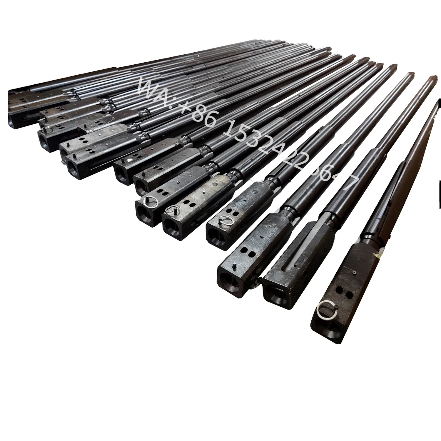
One option is a side-door overshot as shown in Figure 1. This method is similar to a regular overshot, except that it features a removable side door, so that the tool can be put together around the wireline at the well head itself. It is then possible to run the tool on some tubing or on the drillpipe, downhole alongside the wireline in order to make direct contact with the tool. This stops the wireline from being at risk of parting.
It is not recommended that side-door overshots are used with deep open hole intervals. This is because it introduces the potential for keyseating, or differential sticking in the mud cake.
Throughout modern drilling, the most successful method to retrieve stuck logging tools is through the cut-and-thread method. This involves cutting the wireline at the surface, and then threading it through a pipe string while the pipe is lowered, until it engages with the logging tool. The line must be secured at the surface, and rope sockets need to be fitted to each end to form a spearhead both emerging from the top of the well, and a spearhead overshot at the logging end. A stand of pipe will then be hung in the derrick, allowing enough of an overshot at the bottom to catch the logging tool, or at least the wireline rope socket. When the upper end of the line is spooled down through the interior of the pipe until the overshot connects with the spearhead at the bottom, then the pipe will be run into the hole. This is repeated with additional stands until the bottom of the string is close enough to the fish. When this is achieved, the spearhead overshot can be disengaged and the overshot can be circulated clean, before it engages with the tool. When the fish has been grasped securely, the wireline will be pulled free from the rope socket, and then spooled out of the hole, and the tool itself recovered with the fishing string. Although the cut-and-thread method takes a lot of time, and comes with a certain amount of risk, it vastly improves the chances of recovering the wireline and tool fully, and is much quicker than trying to engage with the wireline in an open hole.
If it is not possible to use either a side-door overshot or a cut-and-thread, then an alternative is to break the weakpoint, and then recover the cable and use the drill pipe to fish for the logging tool. If tool recovery is not an option, then a last resort is to push it to the very bottom of the hole, and then plug it using cement.
Wirelines that are wadded or tangled can be retrieved with a wireline barb or rope spear. This penetrates the debris, engages with it, and then allows the debris to be pulled away, as shown in Figure 2. This is one of the most basic forms of fishing tool, and gives strong results when used in the right way.
DeGeare, J. (2003). The Guide to Oilwell Fishing Operations: Tools, Techniques, and Rules of Thumb (Gulf Drilling Guides). 1st ed. Houston: Gulf Professional Publishing.

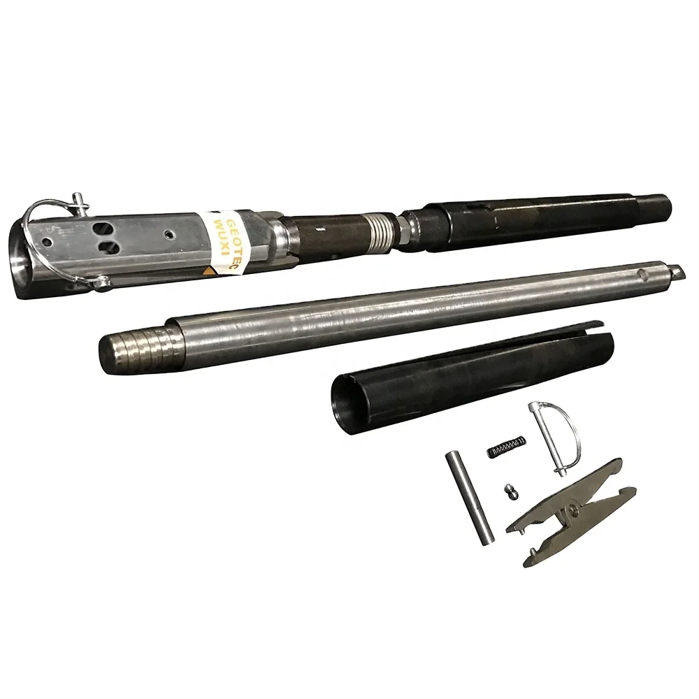
An OVERSHOT is attached to the end of a wireline and lowered into the outer tube. The Overshot then locks on to the Latch Head Assembly at the top of the core barrel.
The inner tube is then pulled to the surface with the core sample inside. Givens International offers an overshot for a spear point or quad latch head.
The Slickline/Braided Line Swivel Joint is designed to ensure free rotation of down hole tool string assemblies even when the tool string is held in significant tension.
The heavy-duty versions are also capable of withstanding high impact forces suitable for use with the latest generation of high impact jars. By preventing the build-up of rotational torque from the tool string the chances of cable damage is significantly reduced.
Hunting Swivel Joints are available in all common industry toolstring sizes and are manufactured with either sucker rod or integral quick connections as per customer requirements

That’s exactly what National EWP was looking for when it put the new Epiroc DiscovOre wireline coring system and Arrow 3S overshot to the test in a side-by-side field trial at a customer’s Arizona property. Both systems were run on the job’s Christensen CS14.
The site superintendent explains that a key focus area for almost all wireline core drilling is reducing “hit time,” or the time it takes for an overshot to lock onto the coring assembly after falling hundreds or thousands of feet through drilling mud. “Shortening the hit time when you’re coring 5- and 10-foot lengths can make a huge difference over a shift. When you can consistently shorten the tube-to-tube cycle, you get more feet drilled in a day.”
Greg Leavitt, Epiroc sales specialist in tooling exploration, visited the site to help with the timings. Leavitt says that while faster hit times were definitely the focus of comparison, safety is National EWP’s top priority. “It’s important not only to National, but their mining customers. Their customers only permit safe operators on their projects. When they choose National EWP, they know they’re guaranteed that. That’s why National is interested in the DiscovOre system and Arrow 3S overshot. They never stop looking for safety improvements.”
The system is consistent with the National EWP “Safety. Own it.” operating philosophy as well as their continuous equipment maintenance and upgrade programs. Examples include the use of state-of-the art, automated rod loaders, hands-free makeup and breakout systems, and custom-designed rod handling tools.
The National crew was completing the final hole of a five-hole survey in an especially problematic, highly fractured formation. Blockages frequently limited core lengths to just 5 feet or less. “Every extra minute waiting for the overshot to hit and lock onto the tube is multiplied by the number of trips out of the hole over each 12-hour shift,” Leavitt says. “It’s a significant amount of lost coring time.”
The system range covers all exploration tool sizes and works with common makes of exploration drill pipe, tubes and bits. Holes ranged from 300 to 2,100 feet with HO-size tooling set up for 10-foot-long, 2.4-inch-diameter triple-tube coring. The crew alternated every other sample between the DiscovOre system and their unmodified, traditional head and overshot system, as another of the system’s advantages is that it is compatible with exploration tooling the company already has.
The DiscovOre system design addresses several design weaknesses of older style wireline systems, according to the company. It completely eliminates the spearpoint, and there are no roll pins in the tube head to fail. The streamlined design decreases overall weight for greater ease and safety in handling. The Arrow 3S overshot locks into the coring assembly automatically and hits faster.
“The customer National is working for now, for instance, requires a three-fold redundancy in safety mechanisms.” One of those, Leavitt explains, is the helper’s ability to manually twist-lock the overshot in place. “What their customer likes about the DiscovOre system is that it has an automatic latch. It doesn’t need a twist lock. You don’t have to touch it, and that’s the ultimate in safety.”
Growth in the ‘50s fueled new technology, and in 1953, Longyear applied for a patent on the first wireline core retrieval system, the Q™ Wireline. Tom Shenosky, Epiroc product manager of Exploration Rock Drilling Tools, says many wireline tooling systems produced by various manufacturers over the years have, for the most part, simply continued the original system’s design based on spearhead, roll pins and open bearing assembly.
That changes with the DiscovOre. The overshot and tube head are key focus points for improving both efficiency and safety. The system has no spearhead and no roll pin in the head assembly, with sealed bearings and a sleek design, reducing its mass by about 10 pounds.
The DiscovOre and Arrow 3S design “flips” the locking system. Instead of a spearpoint that plunges into an overshot assembly, the Arrow 3S latching takes places within the head assembly. The company says the design isn’t just safer on the string. A common safety practice for other systems is to fold a spearpoint down when it is on the rack waiting for reuse. But spearpoint roll pins commonly jam up after they have been in use for some time. When handlers can no longer fold them to the side, they are left extended straight out from the body, presenting a risk of injury to workers moving around them.
The roll pin and the spearhead are the sole points of support, core after core, all shift long, day after day. That makes them critical wear points and common cause of premature failure. When they fail inside a hole, exploration drillers waste production time trying to fetch the tube out. Failing outside of the hole results in heavy tubes dangerously bouncing around a helper and driller in a confined work space. The company says DiscovOre eliminates the spearhead and the roll pins in the tube head altogether, providing not only safer, but more reliable and more efficient solution for wireline systems.
The Series 10 Sucker Rod Overshot is a small, rugged tool designed for engaging and retrieving sucker rods, couplings, and other items from inside tubing strings.
Series 20 Short Catch Sucker Rod Overshots are designed for conditions when sucker rods, couplings, and other portions of a fish are too short for retrieval with a standard overshot.
The Hydraulic Release Overshot was designed to aid in the recovery of a stuck fish in a horizontal drilling application where normal rotation for release is not obtainable.
The Series 150 Releasing and Circulating Overshot consists of three main external parts: a Top Sub, a Bowl, and a Guide. Internal catch and pack-off parts are determined by the diameter of the fish. Each assembly is designed for a maximum catch diameter.
A Series 160 Side Door Overshot is recommended when fishing for cable tools or conductor lines in cased holes. The side door overshot is run in on tubing or drill pipe.
A Lead Impression Block is an effective tool used to determine dimensions, configuration, condition, and location of the top end of a fish in the hole.
Rotary Die Collars are the simplest external catch fishing tools designed for retrieving a fish from the hole. Die Collars are available in two types: Type A and Type B.
Releasing Spears provide a positive means to engage and retrieve an internal fish from the well. The design of this rugged, dependable, and inexpensive internal catch fishing tool ensures positive engagement, easy release and re-engagement. It may be used with other equipment such as pack-off assemblies and internal cutters.
The Packer Retriever Spear is designed to remove drillable full-bore packers from the well casing. With appropriate dressing, the tool can mill through the packer if necessary.
The Core Type Junk Basket is an easy to use junk retrieval tool designed to effectively remove small objects such as bit cones, slips, hand tools, and tail chains from the hole.
The Fishing Magnet is designed to retrieve small metal, oddly shaped objects such as mill shavings, bit cones, cutters, bearings, slips, tong pins and hand tools for the bottom of the well bore.
The Magna Fish™ Fishing Magnet is designed to retrieve small metal, oddly–shaped objects such as milling shavings, bit cones, cuers, bearings, slips, long pins, and hand tools from the boom of the wellbore. Typically, these objects are the result of bit failures, and accumula!on of mill cuttings, or simply accidental droppings of unmillable objects.
The Superior Hydraulic Jar is a straight pull, up only, jarring tool that utilizes a special valve section to meter oil from one side of the piston to the other side. This allows for controlled jarring action during stuck fish recovery.
One of the most common tools used for any kind of fishing job is the bumper sub. The tool’s design allows full torque and unrestricted fluid circulation at all times.
The Jar Tester is a versatile machine for setting, checking, or testing pull loads of a variety of tools with outer diameters up to 11 inches. The Jar Tester is capable of exerting tension or compression loads in a controlled manner.
The Type J Safety Joint provides a release option from tools such as taper taps or die collars that are normally non-releasable. It also provides a way to connect or disconnect fishing string and stuck fish.
The Bi-Directional Coiled Tubing Jar is designed to hit upward and downward blows. It can be dressed to only hit up or down. These tools’ small outside diameters and shorter lengths make them ideal for milling, drilling, workover, remedial, or completion operations, especially in vertical, deviated, and ultradeep wellbores.
The double-acting, Bi-Directional Coiled Tubing Energizer is an impact enhancement tool designed for slim holes (generally a well bore less than 6 inches in diameter). Its function is to supply intensified impact during the jarring operation by providing or enhancing jar impact from energy stored within its oil-filled compression chambers.
Junk Mills are hard-faced with sintered tungsten carbide particles that mill away stuck fish that can not be retrieved with conventional fishing methods. These tools are highly resistant to impact and their super rates of penetration result in fewer round trips. Their maximum useful life is enhanced by their self-sharpening feature.
The Welded Cup Junk Sub is an accessory tool that prevents cuttings from milling or drilling operations that are too heavy to be circulated from settling at the bottom of the hole.
The Threaded Cup Junk Sub is an accessory tool that prevents cuttings from milling or drilling operations that are too heavy to be circulated from settling at the bottom of the hole.
The automatic spring-fed knives feature of this tool prevents excessive strain from being applied from the rig floor that could cause the knives to burn or break before the cut is completed.
These quick, smooth operating tools allow for fast recovery of tubing or drill pipe. A hydraulically fed piston forces the knives of this cutter into the pipe to give the operator sensitive cutting control.
The dependable Hydraulic Wireline Jar utilizes a hydraulic system that permits controlled jarring in measuring line or stranded wireline operations when electrical continuity below the jar is not required.
The Hydraulic Rod Jar provides a dependable means for controlled jarring in sucker rod operations when electrical continuity or circulation to the tools or below the jar is not required.

[0001] The invention relates generally to a wireline overshot for connecting a wireline to an article within a borehole (or within a downhole tool in the borehole) and/or for retrieving an article from a borehole (or from a downhole tool disposed in the borehole).
[0002] A "wireline" overshot is used to connect a wireline to an article within a drill string. The article can be, but need not be limited to, a wireline coring inner barrel, a soft material sampling tool, a data gathering assembly, or an optional portion of a downhole drilling assembly. The wireline overshot may also be referred to as a fishing tool. In one example, the wireline overshot connects to the article within the drill string by latching over a spearhead coupled to the article. In another example, the wireline overshot may latch onto the article within the drill string by engaging a circular (or receiving) portion of the article. The wireline is commonly a flexible wire rope but may also be a solid wire (or "slickline"), synthetic braided rope, or small-diameter, flexible tubing. The wireline is typically lowered and raised by a winch.
[0003] In a typical core barrel retrieval operation, a wireline overshot is lowered on the end of a wireline down the drill string, where it latches onto an inner tube assembly of a core barrel disposed within the drill string. The wireline overshot is then pulled back to the surface with the attached inner tube assembly. At the drill floor, the inner tube assembly is held in a clamp or lowered onto the drill floor. An operator releases the wireline overshot from the inner tube assembly manually and sets the wireline overshot aside. In cases where the wireline overshot needs to be unlatched from the inner tube assembly while still within the drill string, the method of unlatching the wireline overshot is commonly one of free-falling a release sleeve onto the wireline
overshot, tensioning and releasing the wireline to ratchet a release pall, and repeated pulling or releasing of the wireline to shear a release pin. All of these operations require the wireline overshot to be reconfigured or rebuilt at the surface before it can function as an overshot again.
[0004] In a first aspect of the invention, an overshot comprises a sleeve, a coupling member having a latched state and an unlatched state disposed at a first end of the sleeve, and a load-responsive toggle mechanism for alternating the coupling member between the latched state and the unlatched state disposed at a second end of the sleeve.
[0005] In a second aspect of the invention, an overshot comprises an outer sleeve and a coupling member disposed a first end of the outer sleeve. A first rotator is disposed within the outer sleeve and configured to alternately engage and disengage from the coupling member, thereby toggling the coupling member between an unlatched state and a latched state. A second rotator is disposed within the outer sleeve and configured to selectively displace and rotate the first rotator in response to an applied load. A weight member is disposed at a second end of the outer sleeve for applying a load to the second rotator.
[0006] In a third aspect of the invention, a method of connecting or disconnecting a wireline from an article comprises providing an overshot comprising a sleeve, a coupling member having a latched state and an unlatched state disposed at a first end of the sleeve, and a load-responsive mechanism for alternating the coupling member between the latched state and the unlatched state disposed at a second end of the sleeve. The method includes coupling a wireline to the load-responsive mechanism, aligning the article with the coupling member, and selectively activating the load- responsive mechanism to alternate the coupling member between the latched state where it engages the article and the unlatched state where it disengages from the article.
[0012] FIG. 4 shows a weight jar assembly of the overshot of FIG. 1 applying a load to an upper rotator of the overshot of FIG. 1 while the overshot is in an unlatched state.
[0016] FIG. 8 shows a weight jar assembly of the overshot of FIG. 1 applying a load to an upper rotator of the overshot of FIG. 1 while the overshot is in the latched state.
[0017] FIG. 9 shows the keys of the lower rotator of the overshot of FIG. 1 released from the key slots of the key holder sleeve of the overshot of FIG. 1.
[0019] FIG. 11 shows the overshot of FIG. 1 after it has engaged an inner tube assembly within a drill string and has been retrieved to the surface with the inner tube assembly.
[0020] FIG. 1 is a cross-section of an overshot 10 for connecting a wireline to an article. The overshot 10 includes a cap 60 for connection to a wireline. A weight jar assembly 44 is coupled to the cap 60. The weight jar assembly 44 may include a weight bar 19 attached to the cap 60 by fasteners 21 , e.g., thread-and-set screws, and a jar stem 23 attached to the weight bar 19 by fasteners 25, e.g., thread-and-set screws. The jar stem 23 is received in a sleeve 22 and retained in the sleeve 22 by a jar bushing 27 mounted at the upper end of the sleeve 22. A toggle head 13 is received in the sleeve 22 and is positioned below the jar stem 23. A coupling member 14 is coupled to the toggle head 13 for engaging an article of interest. The article of interest may be any tool requiring a releasable connection with a wireline. For example, the article may be an inner tube assembly used to collect core samples from a subsurface formation, a soft material sampling tool, a data gathering assembly, and a component of a downhole drilling assembly. Connection and release of the overshot 10 from the article can be made at the surface, within a borehole, or within a tool disposed in the borehole.
[0022] Returning to FIG. 1 , the lifting dogs 18 are pivotally coupled to an axle 26 of the toggle head 13. A spring 28 is disposed between the upper ends 30 of the lifting dogs 18 to bias the upper ends 30 of the lifting dogs 18 away from each other. The pivot joint 33 between the lifting dogs 18 causes the lower ends 32 of the lifting dogs 18 (which include the hooks for engaging a part) to be biased in a reverse direction to the upper ends 30 of the lifting dogs 18. A toggle mechanism for moving the lifting dogs 18 between the latched and unlatched states includes a lower rotator 34. In the unlatched state, the upper ends 30 of the lifting dogs 18 are received within a bore of the lower rotator 34 so that the wall of the lower rotator 34 acts as a restraining ring around the upper ends 30 of the lifting dogs 18. In this unlatched state, the upper ends 30 of the lifting dogs 18 are forced towards each other against the force of the spring 28 and the lower ends 32 of the lifting dogs 18 are forced away from each other. The lower rotator 34 is axially movable along the toggle head 13 and sleeve 22. To transition the overshot 10 to a latched state, the lower rotator 34 is moved a sufficient distance in an upward direction to release the upper ends 30 of the lifting dogs 18 from the lower rotator 34. Once the upper ends 30 are released, the spring 28 would move the upper
[0023] The toggle mechanism includes an upper rotator 40 disposed about the shaft 24. The upper rotator 40 is held in place above the lower rotator 34 (and about the shaft 24) by a spring 42. The term "rotator," as used herein and above, means a part that can rotate or that can rotate another part. In one example, the upper rotator 40 is configured to rotate the lower rotator 34. The upper rotator 40 is slidable along the shaft 24 upon application of a load to the upper rotator 40 by the weight jar assembly 44. For the upper rotator 40 to be slidable, the load applied by the weight jar assembly 44 must be sufficient to overcome the biasing force of the spring 42 holding the upper rotator 40 in place. As will be further explained below, the load should also be sufficient to overcome the biasing force of the spring 38 holding up the lower rotator 34, or the biasing force of the spring 38 holding up the lower rotator 34 should be less than that of the spring 42 holding up the upper rotator 40. A wireline (not shown) coupled to the weight bar 19 through the cap 60 is used to control the position of the jar stem 23 (of the weight jar assembly 44) within the sleeve 22. The jar stem 23 is movable between an upper position limited by the jar bushing 27 (at the upper end of the sleeve 22) and a lower position limited by the upper rotator 40. When the weight jar assembly 44 rests on the upper rotator 40, it applies a load to the upper rotator 40. As will be explained below, this load assists in shifting the lifting dogs 18 between the latched and unlatched states. Contact is required between the jar stem 23 and the upper rotator 40 to allow the weight jar assembly 44 to apply a load to the upper rotator 40. Contact can be achieved in one of two ways. One way is by letting go of tension in the wireline (not shown) coupled to the weight bar 19 so that the jar stem 23 slides down the shaft 24 to contact the upper rotator 40. The other way is by moving the overshot 10 upwardly so that the upper rotator 40 slides up the shaft 24 to contact the jar stem 23. A jar bushing
12 latched into a core barrel 56. The overshot 10 is in an unlatched state, with the lifting dogs 18 slid down the spearhead 16 and held open by the shoulder 57 of the spearhead 16. This frees the lower rotator 34 to rotate without the friction that would be caused by the spring 38. In the example shown in FIG. 3, tension in the wireline has been relaxed, allowing the weight jar assembly 44 to rest on and apply a load to the upper rotator 40. Relative motion between the overshot 10 and the wireline (not shown) is used to bring the jar stem 23 of the weight jar assembly 44 in contact with the upper rotator 40. Relative motion can be achieved by releasing the weight jar assembly 44 from above,
e.g., through relaxation of tension in the wireline coupled to the weight jar assembly 44, or by moving the overshot 10 upwardly. The weight jar assembly 44 applies weight to the upper rotator 40 and, as shown in FIG. 4, causes the upper rotator 40 to slide down the key holder sleeve 46 and engage the lower rotator 34. As shown in FIG. 5, the upper rotator 40 pushes the lower rotator 34 down until the keys 54 (on the lower rotator 34) are positioned below the keys 48 (on the key holder sleeve 46). As previously explained, the load applied by the weight jar assembly (44 in FIG. 1 ) must be sufficient to overcome the force of the spring (42 in FIG. 1 ) holding up the upper rotator 40 and the force of the spring (38 in FIG. 1 ) holding up the lower rotator 34. The lower rotator 34 then rotates clockwise (looking down) as the tension of the spring (38 in FIG. 1 ) pushes the lower rotator 34 upwardly against the beveled surface 62 of the upper rotator 40. The keys 54 slide into the key slots 50 without the stop pins 52, as shown in FIG. 6. The lower rotator 34 moves upwardly as the keys 54 slide upwardly inside the key slots 50. As shown in FIG. 7, this causes the upper ends 30 of the lifting dogs 18 to be released from the lower rotator 34. The spring 28 moves the upper ends 30 of the lifting dogs 18 outwardly, which causes the lower ends 32 of the lifting dogs 18 to move inwardly and latch onto the spearhead 16. In the latched state, the weight jar assembly 44 is held again in tension to avoid exerting weight on the upper rotator 40, and the upper rotator 40 is held above the lower rotator 34 by the spring 42. The lower rotator 34 is held in place by the keyed connection described above and the force of the spring 38.
[0026] To release the lifting dogs 18 from the spearhead 16, the weight jar assembly 44 is again brought into contact with the upper rotator 40 to apply a load to the upper rotator 40, as shown in FIG. 8. As previously explained, the weight jar assembly 44 can either slide down to contact the upper rotator 40, or the overshot 10 can be moved upwardly to allow the upper rotator 40 to slide up and contact the weight jar assembly 44. The upper rotator 40, under the load of the weight jar assembly 44, slides down the key holder sleeve 46 to engage the lower rotator 38 and push the lower rotator 38 down so that, as shown in FIG. 9, the keys 54 are positioned below the keys 48. For this to happen, the load applied by the weight jar assembly 44 must be
[0027] The overshot 10 can be used to connect a wireline to an article, such as an oilfield tool, either at the surface or in a borehole. The overshot 10 can be disconnected from the article by the same action used in connecting the overshot 10 to the article, as described above. The overshot 10 can be used in any drilling or wireline operation. For illustration purposes, FIG. 10 shows the overshot 10 suspended at the end of a wireline 70 in preparation for lowering the overshot 10 into a drill string 72 containing a core barrel with an inner tube assembly. The drill string 72 is disposed in a borehole 73 drilled in a subsurface formation 75. FIG. 11 shows the overshot 10 after it has engaged the inner tube assembly 12 and been retrieved to the surface with the inner tube assembly 12. A handling arm 74 holds the inner tube assembly 12 while the overshot 10 is disengaged from the inner tube assembly 12 as described above.

There are two ways to do core drilling: conventional and wireline. The main difference is how you recover the core sample once the inner tube is full. In conventional drilling, the entire drill string needs to be pulled out of the bore hole for each drilling cycle. This means that all the drill rods must be removed from the hole and the threads must be taken apart and rejoined for each core sample.
In wireline core drilling, a piece of equipment called an overshot is sent down the hole to release and retrieve the inner tube. The overshot and inner tube are then brought up to the surface using a wireline hoist, allowing the rods and core bit to remain in the hole. A new inner tube is then lowered down and locked into place. The wireline method is more common these days as it is more efficient and safe.
While the drilling cycle is underway, drilling fluids are flushed down into the drill string. These fluids will be under pressure and will flush past the face of the drill bit as it drills, cooling it and bringing the drill cuttings back up to the surface. When the drill bit starts to wear out, it will no longer cut well. It will need to be replaced and the entire drill string will need to be removed from the bore hole in both conventional and wireline methods. Choosing the right core bit for the type of ground becomes very important in order to get the longest bit life and reduce downtime.


 8613371530291