
alberta power tong companies free sample
In your work you rely on having suppliers who use the best equipment to complete your jobs. Among the most important pieces of equipment required for oil drilling and completions are power tongs. Drifters Casing Service is a local provider of power tongs services in Grande Prairie and Whitecourt areas with a reputation for expertise and reliability.
Eckel.Eckel is the one of the world’s leading power tong manufacturers. Each Eckel tong must pass a comprehensive compliance checklist so it’s ready to meet requirements in the field.
Universe. Since 1965, Universe Machine Corporation has supplied trustworthy steel products for the oilfield industry. Their quality standard system ensures that each power tong meets your application requirements.
We have many sizes of power tongs to fit the size of your pipe, from 2-3/8″ to 13- 3/8″. And our power tongs equipment offers a wide torque range to suit the job.
In addition to power tongs in Grande Prairie, we provide all other casing and tubing services you may need, including integral tubing tongs. You can also monitor your equipment with WinCatt Computer Torque Monitoring that we can provide and monitor on your behalf. All equipment can be used in drilling and completions work.
We’re your provider of oil field drilling and completions services that require power tongs and related oilfield equipment. Since 2000, our locally-owned and operated company has helped companies like yours get the work done right. Contact us for more information.
Our experienced and skilled power tong technicians play a major role in the safety and efficiency of a casing run. This makes the selection of your power tong service company a key component of overall performance.
ProTorque attracts and employs some of the industry’s most talented and experienced casing running technicians. Every detail of a casing run must be considered when looking for cost savings and efficiency; particularly on long production strings where every second counts while maintaining a safe operation. When making-up hundreds of connections, filling on the fly and selecting the correct handling equipment (air or hydraulic powered slips); we save time and effort on long challenging casing runs. ProTorque can meet handling requirements of up to 500 tons of hoist capability.

For information about fatigue and safety, please see the Workplace Health and Safety Bulletin, Fatigue and Safety at the Workplace. A copy of this publication can also be obtained from any OHS office in Alberta. To find an office near you, please phone the OHS Contact Centre toll-free at 1-866-415-8690.
Disclaimer: In the event of any discrepancy between this information and Alberta Employment Standards legislation, the legislation is considered correct.
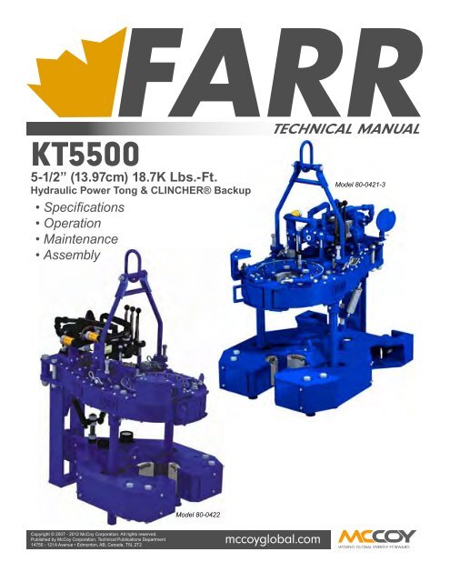
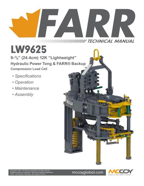
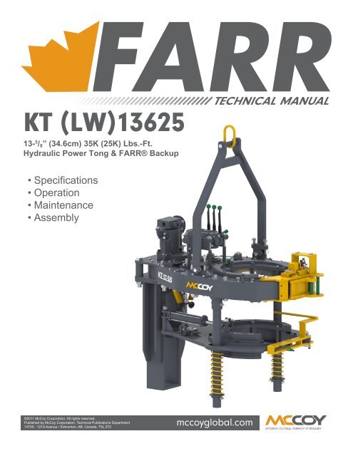
A two-speed Hydra-Shift® motor coupled with a two-speed gear train provides (4) torque levels and (4) RPM speeds. Easily shift the hydraulic motor in low speed to high speed without stopping the tong or tublar rotation, saving rig time.
A patented door locking system (US Patent 6,279,426) for Eckel tongs that allows for latchless locking of the tong door. The tong door swings easily open and closed and locks when torque
is applied to the tong. When safety is important this locking mechanism combined with our safety door interlock provides unparalleled safety while speeding up the turn around time between connections. The Radial Door Lock is patented protected in the following countries: Canada, Germany, Norway, United Kingdom, and the United States.
The field proven Tri-Grip® Backup features a three head design that encompasses the tubular that applies an evenly distributed gripping force. The Tri-Grip®Backup provides exceptional gripping capabilities with either Eckel True Grit® dies or Pyramid Fine Tooth dies. The hydraulic backup is suspended at an adjustable level below the power tong by means of three hanger legs and allowing the backup to remain stationary while the power tong moves vertically to compensate for thread travel of the connection.
The present invention relates to tools used in the oil and gas drilling industry, such as power tongs, to grip and apply torque to drill pipe and other tubular members. More particularly, the present invention relates to the jaw members of the power tong and an improved structure for such jaw members.
The use of power tongs to make up and break apart threaded connections on drill pipe and similar tubulars is well known in the oil and gas industry. Typically the power tong will have at least two jaw members which ride on cam surfaces in order to bring the jaws into and out of contact with the tubular. An example of this camming mechanism is shown in U.S. Pat. No. 5,435,213 to David A. Buck, which is incorporated by reference herein. The jaw members themselves have also been the subject of inventive effort as evidenced by U.S. Pat. Nos. 4,709,599, 4,649,777 and U.S. application Ser. No. 08/805,442, filed on Feb. 25, 1997, all to David A. Buck and all incorporated by reference herein. The jaw members typically will have roughened or knurled gripping surface which will allow the jaw members to superficially penetrate or "bite" into the outer surface of a tubular and thereby securely grip the tubular.
Generally, the jaw members are mounted between upper and lower cage plates which may rotate within the body of the power tongs. The jaw members mounting in the cage plates allows the jaw members may move radially toward and away from the tubular in order to selectively engage and disengage the tubular. As explained in more detail below, this radial movement is effected by rollers on the jaw members traveling along cam surfaces positioned on a ring gear. Applying torque to the ring gear will urge the rollers or cam followers of the jaw members up the cam surfaces so that the jaw members close on the tubular. The power tong is structured so that initial rotation of the ring gear causes the jaw members to exert radial force on the tubular, but the jaw members do not initially transfer torque to the tubular. However, continued rotation of the ring gear will begin to impart both an increasing radial force and torque to the tubular.
Therefore the present invention provides an improved power tong jaw having a jaw body with a roller aperture formed therein. A jaw roller is positioned in said roller aperture by some type of retaining surface, such as a roller pin. Additionally, a friction reducing surface is formed between the jaw roller and the jaw pin. In one embodiment, this friction reducing surface comprises a plurality of needle bearings.
FIG. 1 is a top view of a conventional power tong with the cover plate and upper cage plated removed in order to show the power tong"s main internal components.
FIG. 1 is a top view of a prior art power tong 1 such as disclosed in U.S. Pat. No. 5,435,213 to David A. Buck, which is incorporated by reference herein. FIG. 1 illustrates tong 1 with the top cover plate and top cage plate removed exposing to view ring gear 5, lower cage plate 7 and jaw members 10. Jaw members 10 are positioned between lower cage plate 7 and an upper cage plate (not shown). Jaw members 10 are also positioned in slots which are formed in the upper and lower cage plates such that jaw members 10 may move radially toward and away from tubular 8. As seen in FIG. 2, conventional jaw member 10 will have a jaw body 11 and a die 14 which will provide the surface actually engaging the tubular 8. Die 14 will attach to the front of jaw body 11 and be held in place when die clips 15 are attached to jaw body 11 by way of conventional screws (not shown) engaging clip apertures 16. The rear of jaw body 11 will have a roller aperture (not seen in FIG. 2, but similar aperture 23 seen in FIG. 4) which receives roller 12 such that roller 12 may be pivotally held in place by jaw pin 13. As suggested by FIG. 1, jaw member 10 is positioned in power tong 1 such that jaw roller 12 may engage cam surfaces 4 and 6. Ring gear 5 is mounted in the body 2 of power tong 1 on ring gear rollers 3 such that ring gear 5 may rotate relative to both the tong body 2 and the cage plates. Relative movement between ring gear 5 and the cage plates causes rollers 12 of jaw members 10 to ride onto positive cam surface 6 or neutral cam surface 4 and engage or disengage tubular 8. FIG. 1 illustrates the relative movement between cage plate 7 and ring gear 5 as having moved jaw members 10 on to positive cam surface 6 and into engagement with tubular 8. Generally a friction causing brake band (not shown) will hold the cage plates stationary as ring gear 5 begins its initial rotation. This allows jaw members 10 to ride onto positive cam surface 6 and engage tubular 8 without torque being applied to jaw members 10 and hence without torque being applied to tubular 8. As jaw members 10 travel further on cam surface 6, jaw members 10 tend to become, in effect, wedged between tubular 8 and cam surface 6. This produces the radial load on tubular 8 and imparts torque to the cage plates through jaw members 10. Continued rotation of ring gear 5 will eventually generate sufficient torque for the cage plates to overcome the frictional resistance of the brake band. At this point, the cage plates and ring gear 5 rotate together and torque will begin to be applied to tubular 8. The continued rotation of ring gear 5 not only supplies torque to jaw members 10, but also produces additional radial force against tubular 8. In order to prevent slipping between tubular 8 and jaw members 10, it is important that the radial force be sufficient to securely grip tubular 8 prior to significant torque being applied to jaw members 10. When tubular 8 is a comparatively small tubular, preventing slippage becomes even more difficult since small tubulars present less surface area to be gripped. Therefore it is advantageous to eliminate any unnecessary frictional forces that tend to prevent torque from producing a corresponding radial load on jaw members 10. As mentioned above, one source of friction are the rollers 12 of jaw members 10. Therefore the present invention provides a jaw member that substantially reduces the frictional forces caused by rollers 12.
FIGS. 7-10 illustrate further alternate embodiments wherein roller retaining surface 35 comprises a structure other than a jaw pin 36. FIG. 7 shows a jaw member 20 having a jaw body 21 and a roller aperture 23 with open sidewalls 47. Roller aperture 23 is sized to have a diameter just slightly larger than jaw roller 22. Therefore when jaw roller 22 is inserted in jaw aperture 23, jaw roller 22 will be able to rotate within jaw aperture 23. Since roller aperture 23 does not completely inclose jaw roller 22, a section of jaw roller 22 will extend beyond open sidewalls 47 such that jaw roller 22 will be able to contact the cam surface of the power tongs. As seen in FIG. 7, sidewalls 47 will form in this embodiment the retaining surface 35 which holds jaw roller 22 within roller aperture 23. The inner walls of roller aperture 23 will form a contacting surface 46 against which jaw roller 22 will rotate. In this embodiment, a friction reducing surface 31, such as the Teflon® materials described above, is formed on jaw roller 22 such that jaw roller 22 may rotate against contacting surface 46 with a reduced frictional resistance. Alternatively, the friction reducing surface 31 could be formed on contacting surface 46 or even on both jaw roller 22 and contacting surface 46. Jaw member 20 will also include retainer plates 45 which will secure jaw roller 22 from vertical movement in roller aperture 23. The bearing structure shown in FIG. 7 is generally referred to in the art as a "journal bearing".
In operation, a jaw roller 22 will be positioned in roller aperture 23 of the jaw member 20 illustrated in FIGS. 8-10. When roller 22 moves along the cam surface of the power tongs, it will rotate causing the ball bearings 50 in the shallow bearing groove 52 to move along the length of shallow bearing groove 52. As ball bearings 50 enter into curved section 55, circulating channel 51 will transition into deep bearing groove 53. It is preferable that ball bearings 50 move below the surface of aperture wall 54 prior to beginning movement in a vertical direction in curved section 55. Otherwise ball bearings 50 will not be able to roll horizontally and will present a less efficient friction reducing surface. Ball bearings 50 will circulate in the sense that jaw roller 22 is forcibly rolling ball bearings 50 toward one end of shallow bearing groove 52. As ball bearings 50 exit that end of shallow bearing groove 52 and enter in deep bearing groove 53, these ball bearings 50 will force ball bearings 50 in their front to travel along deep bearing groove 53 and enter shallow bearing groove 52 at its opposite end. In this manner, the rotation of jaw member 22 will cause a continuous circulation of ball bearings 50 between shallow bearing groove 52 and deep bearing groove 53.
Nor is the scope of the present invention limited to the specific embodiments illustrated above. Friction reducing surface 31 is intended to include all manner of mechanisms for reducing friction between jaw pin 36 and jaw roller 22. For example, if a proper seal is placed between jaw pin 36 and jaw roller 22, it is envisioned that a viscous liquid could serve as a friction reducing surface 31. All such modifications are considered within the scope of the present invention. Furthermore, those skilled in the art will recognize the significant advantages gained by reducing the friction forces acting on the jaw members of a power tong. For example, applicant has found that the present invention requires significantly less torque to achieve the same radial load as compared to prior art jaws. Applicant achieved these results by employing the present invention in a power tong similar to that disclosed in U.S. Pat. application Ser. No. 08/806,074 to David A. Buck, which is incorporated by reference herein. The power tong in question was a 51/2 inch model tool (i.e., capable of gripping tubulars up to 51/2 inches in diameter) and the test was performed on a 31/2 inch tubular. When the prior art jaw assembly having no friction reducing surface was used in the power tong, a radial load of 40,000 lbs was transmitted to the tubular after the power tong had generate 4000 ft-lbs of torque on the tubular. By contrast, when a jaw as seen in FIG. 3 was used under the same conditions, a radial load of 40,000 lbs was transmitted to the tubular by the power tong generating only 1200 ft-lbs of torque. By way of explanation, it will be understood that it is the friction of the brake band which causes the radial loads given above to significantly exceed the torque loads. The torque load represents the amount of torque transferred to the tubular. However, no torque load is placed on the tubular until after the power tong generates enough torque to exceed the frictional resistance of the brake band. On the other hand, the radial load is being placed on the tubular as soon as the jaw members engage the tubular. This radial load increases on the tubular before the frictional resistance of the brake band is overcome and the radial load continues to increase after the bake band is overcome. Therefore, typically the radial load is relatively large as compared to the torque load placed on the tubular.
K&S Power Tongs Ltd: Lloydminster, AB/SK K&S Power Tongs is a well-known power tong company operating for 20+ years. We are hiring an experienced full-time Power Tong operator immediately. We take care of our employees with competitive pay, health/dental benefits as well as health and wellness spending accounts. Requirements: 3-5 years experience working in the oil and gas industry 2-3 years conventional/ integral power tong experience Volant casing running tool experience an asset Ability to work a rotational days on/off schedule Ability to be on-call during scheduled days on Valid Class 5 driver’s license with clean driver’s abstract H2S, WHMIS, and First Aid/CPR certifications Motivated and safety orientated with good communication skills Mechanical aptitude- working knowledge of equipment and maintenance procedures All applicants must be able to pass drug/alcohol/fitness testing
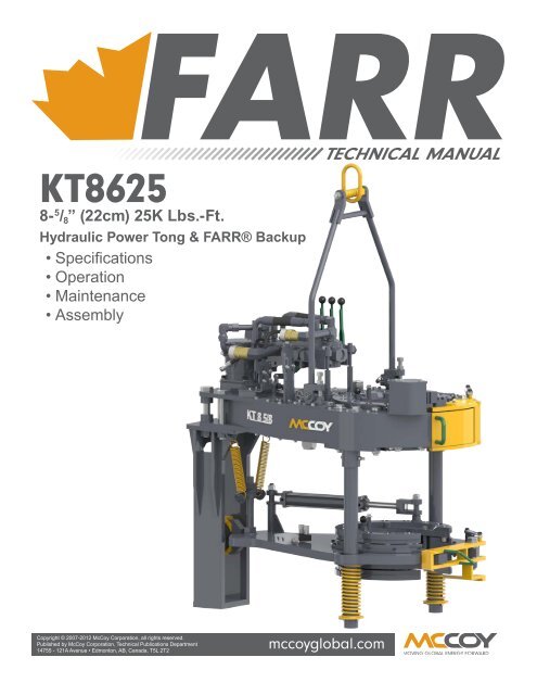
A hydraulic power unit is no longer required for drilling operations, saving rig space, negating power unit transportation concerns, and eliminating possible spillage of hydraulic fluid


 8613371530291