
automated power tong american patent price
This invention is directed to apparatus and methods for aligning wellbore tubulars; and to power tongs used in making and breaking joints of tubular members such as wellbore casing and tubing; to parts thereof; including, but not limited to gripping elements, and methods of their use.
During the drilling of oil and gas wells and the production of materials therefrom, various operations require the connection and disconnection of successive lengths of threaded tubulars such as pipe, casing, or tubing. Tools known as tongs are used to "make" and "break" such connections. Certain known power tongs have a body, a rotary rotatably mounted in said body and at least one active jaw which, on rotation of the rotary is cammed against a pipe in the rotary and grips it for rotation with the rotary. In known arrangements the camming action is generated by a cam member which is bolted to the rotary and is shaped so that the active jaw is cammed against the pipe on rotation of the rotary relative to the active jaw in one sense and will be released on rotation of the rotary relative to the active jaw in the opposite sense.
With known tongs high torques are applied to tubulars due to combinations of factors such as thread sealing requirements, the presence of corrosion, the existence of distortion, and pipe size and weight. Both in the "make" direction of rotation when a shoulder is suddenly encountered, and in the "break" direction at initial engagement of the tong and disengagement of the threads high shock forces may arise; e.g., with a power-driven tong, in excess of 50,000 foot-pounds of torque may be exerted, while relatively small die elements on jaws of the tong engage the pipe with extremely high force loadings. Slippage occurs and pipe surfaces become marred, marked, indented, or otherwise damaged.
Dies for gripping jaws have been provided with multiple serrations, or penetration features, to provide the interference contact at the joint surface. Grip element penetration into the joint surface is limited and controlled. The distribution and balance of grip element energizing forces are critical factors in the design, development and evaluation of such tong mechanisms. Linkages, levers, wedges, and cams are used to balance force components. Grip elements, or dies, are accurately disposed within carrier bodies, or jaws, which span a circumferential segment of the joint surface.
Uneven die loading can cause excessive indentation, marring or damage to a tubular surface. Drag or braking devices are used in certain tongs to effect proper biting of the dies relative to the pipe. The head or other member supporting the dies is frictionally restrained to insure that the dies do not simply rotate with the rotary as the rotary is driven.
Other tongs use an endless belt, chain or flexible material loop for gripping a tubular. Such tongs are disclosed in U.S. Pat. Nos. 3,799,010; 3,906,820; 3,892,140; 4,079,640; 4,099,479; and 4,212,212. There are a variety of problems associated with certain of these tongs:
Jaw/die tongs and the belt/chain tongs are used with relatively hard and rigid metal tubulars such as casing and tubing. If these tongs are used with thick tubulars or tubulars made from relatively "softer" metals or from premium metals such as high alloy steels or low carbon steels or tubulars made from non-metal materials such as fiber glass, they often literally chew up the tubular. The use of strap wrenches is inadequate since the torque applied with such wrenches cannot be precisely controlled.
Certain tubulars are treated with a rust or corrosion resistant material or coating. If the coating is indented, gouged, or broken, its protective purpose is defeated. Producing enough force in a tong to join such tubulars while not injuring a protective coating presents a dilemma.
The present invention, in certain embodiments, discloses a power tong for joining tubulars so that marking of, indentation of, and surface injury to tubulars are reduced or eliminated. In one aspect a power tong is provided and a method of its use for handling tubulars coated with a corrosion-resistant material which should not be broken or penetrated. In one embodiment such a tong has one or more gripping jaws with gripping elements made of aluminum alloys, zinc, zinc alloys, aluminum, brass, bronze, cermet, plastic, fiberglass, metal alloys, or a combination thereof which present a smooth face (straight or curved) to a tubular without any teeth, pointed projections, or toothed dies. In one aspect the gripping elements are releasably connected directly to jaws. In another aspect the gripping elements are releasably connected to a jacket or holder which itself is releasably connected to a jaw.
In one aspect the cylinder(s) are powered by a small air-driven hydraulic pump with an hydraulic fluid reservoir mounted on a plate on the movable or fixed jaw. Air is supplied to activate a motor of the pump and the pump then provides hydraulic fluid to move a piston of the hydraulic cylinder(s). The motion of the cylinder moves the movable jaw on its roller to travel to a pre-load position on the cam. The cylinder applies pressure until the hydraulic pressure is released. A hydraulic fluid accumulator and a valve may be used to maintain hydraulic pressure at all times so that the cylinder(s) continuously maintain the desired load on the jaw until the air supply to the pump is removed.
In another aspect the cylinders are connected to a rotary of the tong or to any other member that rotates with the rotary rather than to a fixed jaw. Such a pre-load system may, according to this invention, be used with any tong including a tong that does use toothed dies.
In one embodiment the present invention discloses a gripping arrangement for a tong with a sheet of grit which is preferably bonded to a carrier plate. In another embodiment the gripping arrangement comprises a layer of flexible material having a smooth flat surface or a surface with ridges and valleys, for example in the fashion of the surface of a file. The flexible material, in one aspect, is metal, for example sheet aluminum, zinc, brass, bronze, zinc alloy, aluminum alloy, stainless steel, or steel having a thickness of about 1.5 mm. The layer of flexible material may be used in conjunction with a carrier plate or on its own. In a further embodiment the gripping arrangement may comprise a layer of perforate material one of both surfaces of which are preferably coated with grit to facilitate adhesion. The layer will typically be formed from metal having a thickness of about 1.5 mm. The layer may be used in conjunction with a carrier plate or used on its own. In yet another embodiment the gripping arrangement may comprise a layer of expanded mesh, e.g. metal mesh, which has been flattened. One or both surfaces of the expanded mesh may be coated with grit and the layer may be used in conjunction with a carrier plate or used on its own. The grit may comprise, for example, diamond dust, particles of silicon, zircon, tungsten carbide and mixtures thereof. The gripping arrangement may comprise end plates which are attached to the carrier plate. Preferably, the carrier plate is provided with side flanges for insertion into a jaw holder. The present invention also provides a jaw assembly fitted with a gripping arrangement in accordance with the present invention. Preferably, the jaw assembly includes a jaw holder having an arcuate recess which accommodates an arcuate pad of resilient elastomeric material which supports said gripping arrangement. Advantageously, at least one shim is provided which is disposed between said arcuate pad of resilient elastomeric material and said gripping arrangement. The shim will be flexible and generally from 0.5 mm to 1.0 mm thick and made from sheet metal. The present invention also provides a tong fitted with at least two such jaw.
In one embodiment the present invention discloses an apparatus for aligning tubulars and includes a guide on one of a power tong and a backup tong. In one embodiment the apparatus has a socket centralizer mounted on said one of said power tong and said backup tong. In one aspect, said one of said power tong and said backup tong is said power tong. In another embodiment, the apparatus includes a power tong and a backup tong, and the guide is mounted on the power tong and apparatus is provided to maintain the power tong and the backup tong in a certain juxtaposition during a stabbing operation. Preferably, said apparatus includes locating rods on one of the power tong and the backup tong and blocks shaped to receive at least the ends of the locating rods on the other of the power tong and the backup tong. Advantageously, the backup tong is provided with at least two prismatic jaw assemblies to locate the backup tong in fixed juxtaposition with respect to a tubular being gripped.
The present invention, in one aspect, provides a jaw unit for use in a tong, which jaw unit comprises a jaw holder and a jaw movable with respect to said jaw holder, characterized in that said jaw is slidably mounted on said jaw holder. Preferably, said jaw is slidable with respect to said jaw holder about an arcuate path. Advantageously, said jaw has a gripping surface which is substantially arcuate for gripping the surface of a tubular and the center of curvature of such arcuate path lies between the center of curvature of said grip ping surface and said arcuate path. The gripping surface may be a continuous surface or defined by several spaced apart gripping elements. Preferably, the center of curvature of said arcuate path lies between the center of curvature of said grip ping surface and said gripping surface. Advantageously, the center of curvature of said arcuate path is substantially midway between the center of curvature of said gripping surface and said gripping surface. Preferably, one of said jaw and said jaw holder is provided with an arcuate track which defines said arcuate path, and the other of said jaw and said jaw holder is slidably mounted in said arcuate track.
The present invention also provides a jaw assembly comprising two jaw units in accordance with the present invention. Preferably, said jaw units are mounted for pivotal movement about a common pivot shaft. Advantageously, said jaw assembly includes means which bias said jaw units apart. The present invention also provides a rotary fitted with a jaw unit in accordance with the present invention, a rotary fitted with a jaw assembly in accordance with the present invention, and a tong fitted with a rotary in accordance with the present invention.
One of the features of existing tongs is that their rotaries are difficult to furnish. Thus, routine maintenance usually involves dismantling the whole rotary, checking the parts and reassembling the whole. While this is a straightforward procedure in the clean conditions of a workshop it can be problematic when carried out in a muddy field, in sand or in snow. The present invention aims to help solve this problem and provides a rotary which comprises a top section, a bottom section, and a peripheral wall therebetween, characterized in that at least one of said top section and said bottom section is provided with an elongate slot which, when said rotary is in use, accommodates a pivot shaft on which a jaw assembly can be pivotally mounted.
Jaw holders and jaws for tongs are traditionally machined from a solid piece. This is a comparatively expensive procedure. The present invention proposes to make such parts from a stack of individually cut laminations.
Such methods and devices including a power tong with at least one jaw with at least one tubular gripping element having a smooth gripping surface (flat or curved) and, in one aspect, such an element which is flexible;
The present invention recognizes and addresses the previously-mentioned problems and long-felt needs and provides a solution to those problems and a satisfactory meeting of those needs in its various possible embodiments and equivalents thereof. To one skilled in this art who has the benefits of this invention"s realizations, teachings, disclosures, and suggestions, other purposes and advantages will be appreciated from the following description of preferred embodiments, given for the purpose of disclosure, when taken in conjunction with the accompanying drawings. The detail in these descriptions is not intended to thwart this patent"s object to claim this invention no matter how others may later disguise it by variations in form or additions of further improvements.
FIG. 2A is a perspective view of a tubular connection system according to the present invention. FIGS. 2B and 2C are perspective views of a casing tong of the system of FIG. 2A.
FIG. 5A shows schematically an initial position of elements of a tong system according to the present invention. FIG. 5B shows pre-loading on a pipe of the jaws of the system of FIG. 5A. FIG. 5C shows a tubular gripped with the system of FIG. 5A.
FIGS. 1A-1C show a typical prior art power tong that uses fixed jaws and a movable jaw to grip pipe for tubular disconnecting and connecting operations. An outer case houses a powered rotary to which the jaws are mounted. A cam surface of the rotary moves a movable (ACTIVE or MASTER) jaw into (and away from) gripping contact with a tubular, e.g. pipe. Each jaw has toothed gripping inserts to facilitate engagement with the surface of the tubular (see FIG. 1B). FIG. 1C shows the tong in an "OPEN" position in which the tubular is not gripped.
The tong shown in FIG. 1A is a Weatherford Model 14.5-50 High Torque Tong. The brochure "New ! Weatherford Model 14.5-50 High Torque Tong," (1991) and the manual entitled "Model 14.5-50 Hydraulic Power Tong Installation, Operation and Maintenance" (1993) are submitted herewith and incorporated herein fully by reference for all purposes. It is to be understood that the teachings of the present invention are applicable to any tong and any tong system that has one or more gripping elements or jaws and that the Model 14.5-50 tong is shown here for illustrative purposes and not by way of limitation of the scope of the present invention.
As shown in FIG. 2A a system 10 according to the present invention includes a power tong 100 according to the present invention which is like the tong of FIG. 1A but which also includes a unique jaw system 110 with inserts 150 on fixed jaws 120 and insert 152 on movable jaw 122 and at least one jaw pre-load assembly like that shown in FIG. 5A. The system 10 includes a free floating backup tong 12.
As shown in FIGS. 2B and 2C, rods 112 are connected to the movable jaw 122. The inserts 150 are on fixed jaws 120 and the insert 152 is on a movable jaw 122 (corresponding to the fixed jaws and active jaw, respectively, of the tong of FIG. 1A).
FIGS. 4A-4G illustrate an alternative jaw mounting system in which holders are interposed between jaw bodies and inserts. The holders protect the jaws from damage if the inserts wear down and a variety of different types and/or sizes of inserts may be used with and interchanged on a single holder. In one aspect it is within the scope of this invention to use these holders to mount conventional toothed dies to a tong jaw and to use them for easy substitution of new and/or different dies.
FIG. 4A shows a jaw system 400 for a tong (like the tong of FIG. 2A) which has two fixed jaws 402 and a movable (movable toward and away from a tubular to be gripped 403) jaw 404. Each jaw 402 has a jaw body 405 with a holder 406 secured thereto. In one aspect dovetail keys 407 secured to the holder or releasably mounted thereto fit in corresponding slots 408 of the jaw bodies 405 to releasably mount the holder 406 to the body. In one aspect dovetail keys 409 releasably mount the holders 406 to jaw bodies 405. The dovetail keys 409 are releasably held in corresponding recesses 411 in the holders 406. One or more dovetail keys 409 may be used (two shown for each holder 406).
FIG. 5A shows a tong system 500 with a tong having a movable rotary 502, fixed jaws 504, 505, and a movable jaw 506 (remainder of tong, not shown, like the tong of FIG. 2A; like the tong of FIG. 1A, but with the added features discussed here). Pins 520 pin the fixed jaws to the rotary. Inserts 522 on the fixed jaws 504, 505 are like the inserts described herein for other fixed jaws. Insert 524 on the movable jaw 506 is like other inserts described herein for movable jaws. A pre-load cylinder 508 to assist in make-up is pivotably connected at one end to the fixed jaw 505 and at the other end to the movable jaw 506. A pre-load cylinder 510 to assist in break-out is pivotably connected at one end to the fixed jaw 504 and at the other end to the movable jaw 506. It is within the scope of this invention for the ends of cylinders connected to the fixed jaws to instead be secured to the rotary or to a support ring or other member that rotates with the rotary. It is within the scope of this invention to employ one cylinder interchangeable between the positions of the cylinders 508 and 510 (FIG. 5A) or one cylinder connectible to the fixed jaw 506 at one end for break-out and at the other end of the fixed jaw 506 for make-up with the other cylinder end secured to the rotary. Rollers 530 rotatably mounted on the movable jaw 506 co-act with cam surfaces 532 on the rotary 502 to move the jaw 506 to operative and inoperative positions.
Air in a line 640 selectively applied with a control system 650 (e.g. mounted on the rig floor, on the tong or remote controlled) selectively actuates the pump 630 to pump fluid through the valve 602 to the pre-load cylinders. The directional control valve 602 is either manually operated or operated by remote control. Correct fluid pressure is monitored with a gauge 651.
As shown in FIG. 5C the tubular 650 has been gripped due to the action of the pre-load cylinder 510 with a suitable pre-load force (e.g., but not limited to, about 500, 1000, 5000, 10000 or 50000 pounds of force). This force is sufficient that when the rotary 502 of the tong is rotated the jaws do not slip on the tubular 650; but the pre-load force is sufficiently low that the jaws do not mark or damage the tubular 650.
FIG. 8 shows schematically a top view of a power tong according to the present invention. A power tong T has an hydraulic motor M with control/monitor apparatus C on a tong case S. A movable jaw J is moved and rotated by a rotary R which is moved by interconnection, via appropriate gearing, by the motor M. Fixed jaws F and G are secured to the rotary R. A first pre-load cylinder D connects the movable jaw J to the fixed jaw G for applying a pre-load to the movable jaw for make-up operations. A second pre-load cylinder L connects the movable jaw J to the fixed jaw F for applying a pre-load to the movable jaw for break-out operations. An insert I (any insert disclosed herein) is secured to the movable jaw J and inserts K (any insert disclosed herein) are secured to the fixed jaws F and G.
FIG. 9 shows a tong jaw 450 according to the present invention with an insert 454 (any insert disclosed herein) and rods 452 secured thereto, e.g. by welding. The rods 452 provide a member to which either a cylinder body or a piston of a pre-load piston cylinder apparatus is connectible. Instead of the rods 452 as shown which extend from above the jaw 450 to a point below it, only rod sections may be used secured to one or both sides of the jaw to provide a securement member for an end of a pre-load apparatus.
According to the present invention a variety of apparatuses and devices may be employed to pre-load a tong jaw having one or more smooth faced gripping insert elements thereon. In one aspect a manually activated pre-load cylinder is used which has fluid or material manually introduced therein to apply a pre-load or manually removed therefrom to release a pre-load. In another aspect a pre-load cylinder is pivotably secured at one end to a rotary or part thereof and the other end is releasably connectible to either end of a movable jaw so that a pre-load may be applied, selectively, to either end of the movable jaw for make-up or break-out operations as desired. In one aspect such a pre-load cylinder has a rod with an end member receivable in and movable in a slot in the movable jaw or there are recesses at either end of the jaw for holding the end member of the rod so that a pre-load can be applied. A secondary small cylinder may be used to selectively move the pre-load cylinder in the jaw slot or it can be moved manually. In another embodiment the tong"s movable jaw has one or more upwardly projecting lugs engageable by a forked piston rod end of a pre-load piston/cylinder that is attached to the rotary. The rotary is rotated so that the jaw is cammed into the pipe to be rotated in a pre-load position and then the forked rod is removed for further tong operations.
In use, two or more jaw assemblies are placed in a tong and are disposed around a length of casing. The jaw assemblies 1001, 1001" are then advanced radially inwardly in the direction of arrows "A" (FIG. 12) until they engage and firmly grip the casing. Because of the flexible construction of the gripping arrangement 1007, the shims 1006 and the arcuate pad 1004, the friction layer 1009 substantially conforms to the circumference of the casing and grips the casing with a substantially uniform gripping action. Once the casing has been firmly gripped the jaws are rotated by the tong in the usual manner. It will be noted that circumferential forces applied to the friction layer are transmitted through the carrier plate 1008 so that any local loads caused, for example by an irregularity in the surface of the casing are redistributed by the carrier plate 1008 and transmitted to the jaw holder 1002 via the side flange 1011 and the arcuate pad 1004 (see FIG. 18).
Referring to FIGS. 19A and 19B of the drawings there is shown a conventional tong assembly which is generally identified by the reference numeral 2001.
The power tong 2002 comprises a pair of gates 2004, 2005 which are held together in the position shown by latch 2006. When the latch 2006 is released the gates 2004, 2005 can be swung open by admitting hydraulic fluid to piston and cylinder assemblies 2007 and 2008. The power tong 2002 also contains a rotary 2009 which is provided with four jaw assemblies 2010. The rotary 2009 can be rotated by a hydraulic motor 2011.
The backup tong 2003 is provided with two gates 2012, 2013 which are held together by latch 2014 but which, when latch 2014 is released can be swung to an open position.
Once the pin is correctly located the stabbing guide is removed. The gates 2004, 2005 of the power tong 2002 and the gates 2012, 2013 of the backup tong 3 are then opened and the tong assembly 2001 moved towards the casing until the lower length of casing lies within the backup tong 2003 and the upper length of casing lies within the power tong 2002. The gates 2004, 2005, 2012, 2013 are then closed and latched. Jaw assemblies in the backup tong are then advanced to engage the lower length of casing while jaw assemblies in the power tong 2002 are advanced to grip the upper length of casing. The hydraulic motor 2011 is then actuated to turn the rotary 2009 and rotate the upper length of casing relative to the lower length of casing. The tong assembly 2001 is supported by a pneumatic lifting cylinder 2015 which enables the power tong 2002 to move towards the backup tong 2003 as the pin enters the socket. Reaction forces are transmitted by columns 2016 disposed to either side of the tong assembly 2001 and by a series of levers in a known manner. It should be noted that the power tong 2002 is free to move in a plane parallel to the backup tong 2003 within certain limits.
The apparatus 2100 comprises a tong assembly 2101 which is generally similar to the tong assembly 2001 shown in FIGS. 19A and 19B and parts of the tong assembly 2101 similar to the tong assembly 2001 have been identified by similar reference numerals in the "2100" series.
Turning first to the guide 2117 it will be seen from FIG. 21B that this comprises four identical components 2118 which are bolted to the top of the power tong 2102. As best shown in FIG. 21C each component is tapered so as to guide the pin of an upper casing to the center of the opening of the power tong 2102.
Referring now to FIG. 22, the backup tong 2103 is provided with three prismatic jaw assemblies 2119a, 2119b, and 2119c which, when actuated, hold a lower length of casing 2120 in a fixed position relative to the backup tong 2103.
As shown in FIG. 23 the backup tong 2103 is provided with three upwardly extending locating rods 2121 which are each provided with a conical tip 2122. Similar, the underside of the power tong 2102 is provided with three blocks 2123 each of which is provided with a recess 2124 shaped to receive the conical tip 2122 of a respective locating rod 2121.
In use, the lower length of casing 2120 is first secured by slips on the rig floor in the usual manner. The gates 2112 and 2113 of the backup tong 2103 are then opened and the tong assembly 2101 moved into position with the backup tong 2103 circumjacent the lower length of casing 2120 and immediately below the socket 2125 thereof.
The gates 2112 and 2113 are then closed by hydraulic piston and cylinder assemblies 2126 and 2127 and the latch 2114 closed. The prismatic jaw assembly 2119a is fixed while prismatic jaw assemblies 2119b and 2119c are automatically advanced by a predetermined distance when the latch 2114 is closed. This grips the lower length of casing firmly and also ensures that the backup tong 2003 is in a fixed position relative to the lower length of casing 2120. The position thus far attained is shown in FIG. 23.
At this time pneumatic lifting cylinder 2115 is extended which lowers the backup tong 2003. The conical tips 2122 of the locating rods 2121 enter the recesses 2124 of the blocks 2123 and thus locate the power tong 2002 with respect to the backup tong 2003. This in turn locates the guide 2117 with respect to the lower length of casing 2120 so that the center of the guide 2117 is coaxial with the axis of the lower length of casing 2120. This position is shown in FIG. 24.
The power tong 2102 is then raised so that the blocks 2123 are well clear of the locating rods 2121. At this point the jaw assemblies in the power tong 2102 are applied to the upper length of casing 2128 and the hydraulic motor 2111 actuated to rotate the rotary and screw the pin 2129 into the socket 2125. During the procedure the power tong 2102 moves towards the backup tong 2103. However, even when the joint is tightened to the required torque the blocks 2123 still lie a short distance above the conical tips 2122 of the locating rods 2121.
At this stage the jaw assemblies of both the power tong 2102 and the backup tong 2103 are relaxed, the gates 2104, 2105, 2112 and 2113 opened and the tong assembly 2101 retracted in preparation for the casing being lowered. It will be noted that one component 2118 of the guide 2117 is mounted on each of the gates 2104, 2105 and accordingly the guide 2117 opens and closes with the gates 2104, 2105.
For certain applications a backup tong is not required, for example where the power tong can conveniently be restrained by a chain attached to the drilling tower.
The apparatus 2200 comprises a power tong 2202 which is generally similar to the power tong 2002. The basic construction of the power tong 2202 is similar to the power tong 2002 and parts having similar functions have been identified by the same reference numeral in the "2200" series.
The main differences are that the apparatus 2200 does not include a backup tong and that it is provided with a guide 2217 and a socket centralizer 2230.
In use, the lower length of casing 2220 is first secured by slips (not shown) with the socket 2225 facing upwardly close to the slips. The power tong 2202 is then lowered onto the socket 2225 so that the socket 2225 enters the socket centralizer 2230 and aligns the socket centralizer 2230, the socket 2225 and the guide 2217. The upper length of casing 2228 is then lowered so that its pin 2229 enters the guide 2217, is center there by and enters the socket 2225. At this point power tong 2202 is raised. Its jaw assemblies are then advanced to grip the upper length of casing 2228 which is then rotated to screw the pin 2229 into the socket 2225. Once the joint is tightened to the required torque the gates 2204, 2205 are opened and the power tong 2202 withdrawn.
The embodiment shown in FIG. 29 is generally similar to that shown in FIG. 28 except that the apparatus 2300 also includes a backup tong 2303. Since the upper length of casing 2328 and the lower length of casing 2320 are being aligned by the guide 2317 and the socket centralizer 2330 no special arrangements need be made for aligning the power tong 2302 and the backup tong 2303.
The procedure for connecting the upper length of casing 2328 to the lower length of casing 2320 is as follows. First, the lower length of casing 2320 is secured in slip (not shown). The gates 2312, 2313 of the backup tong are then opened and the apparatus 2300 maneuvered so that the lower length of casing 2320 is disposed within the backup tong 2303. The power tong 2302 is then lowered until the socket 2325 on the lower length of casing 2320 is received within the socket centralizer 2330. The upper length of casing 2328 is then lowered until the pin 2329 passes through guide 2317 and enters the socket 2328. Only at this stage are gates 2312, 2313 closed and the jaw assemblies of the backup tong 2303 activated to grip the lower length of casing 2320. The power tong 2302 is then raised and its jaw assemblies activated to grip the upper length of casing 2328 which is then rotated to cause the pin 2329 to enter the socket 2325 and the joint to be tightened to the desired torque. The jaw assemblies are then relaxed and the gates 2304, 2305, 2312, 2313 of the power tong 2302 and the backup tong 2303 opened prior to retracting the apparatus 2300.
Various modifications to the embodiments described are envisaged, for example, if desired, the guide and the socket centralizer could be mounted on the backup tong 2303 rather than the power tong 2302. Alternatively, the guide could be mounted on the backup tong without a socket centralizer. Such an arrangement is shown in FIG. 30.
The embodiment shown in FIG. 30 is generally similar to that shown in FIG. 19a and 19b and parts of the tong assembly 2401 similar to the tong assembly 2001 have been identified by similar reference numerals in the "2400" series. One difference is that the top of the backup tong 2403 is provided with a guide 2417.
In use, the lower length of casing 2420 is first secured by stops 2431 on the rig floor in the usual manner. The gates 2412 and 2413 of the backup tong 2403 are then opened. Since two of the four components 2418 of the guide 2417 are mounted on the gates 2412 and 2413 the guide 2417 opens with the gates 2412 and 2413 so that the lower length of casing 2420 can enter the backup tong 2403 when the carriage 2432 which supports the apparatus 2400 is advanced towards the casing 2420 on rails 2433. When the lower length of casing 2420 is fully within the backup tong 2403 the gates 2412 and 2413 are closed. The components 2418 of the guide 2417 have a stepped interior (not visible in FIG. 30) so that the lower part of each component 2418 touches the socket on the top of the lower length of casing 2420 whilst the upper part of the interior of each component 2418 tapers inwardly to form a funnel. Once the lower length of casing 2420 has been gripped the upper length of casing 2428 is lowered through the power tong 2402 towards the lower length of casing 2420. The guide 2417 guides the pin on the bottom of the upper length of casing 2428 into the socket. The power tong 2402 is disposed a small distance above the guide 2417. Once the pin of the upper length of casing 2428 has entered the socket on the lower length of casing the jaws of the power tong 2402 are applied to the upper length of casing 2428 which is rotated until the joint reaches the desired torque.
Referring now to FIG. 38, the rotary 3100 is shown fitted in a tong 3116. As shown in FIG. 39 and 40, the rotary 3100 is formed as a one piece casting which comprises a top section 3117, a bottom section 3118, and a peripheral wall 3119 on which is formed a toothed track 3120. Both the top section 3117 and the bottom section 3118 are provided with an elongate slot 3121, 3122 respectively. Each elongate slot 3121, 3122 has its center of curvature on the center of rotation of the rotary 3100.
As can be seen in FIG. 38 and FIGS. 31 to 37, the sides of the rotary 3100 are provided with cams 3128, 3129, 3130 and 3131 which are screwed to the rotary 3100. The rotary 3100 is located in the tong 3116 by nine guide rolls 3132, five of which are visible in FIG. 38. The guide rolls 3132 each have an upper and a lower roller which bears against the peripheral wall 3119 of the rotary 3100 above and below the toothed track 3120 respectively.
In conclusion, therefore, it is seen that the present invention and the embodiments disclosed herein and those covered by the appended claims are well adapted to carry out the objectives and obtain the ends set forth. Certain changes can be made in the subject matter without departing from the spirit and the scope of this invention. It is realized that changes are possible within the scope of this invention and it is further intended that each element or step recited in any of the following claims is to be understood as referring to all equivalent elements or steps. The following claims are intended to cover the invention as broadly as legally possible in whatever form it may be utilized. The invention claimed herein is new and novel in accordance with 35 U.S.C. § 102 and satisfies the conditions for patentability in § 102. The invention claimed herein is not obvious in accordance with 35 U.S.C. § 103 and satisfies the conditions for patentability in § 103. This specification and the claims that follow are in accordance with all of the requirements of 35 U.S.C. § 112.
The present invention relates to open-head power tongs used in drilling operations, and more particularly, is directed to an improved means of actuating and deactuating the operation of the power tong drive means in response to the opened and closed positions of an access door.
As well known in the drilling industry, power tongs are employed in making-up and breaking-out operations of casings, tubings, rods, pipes and the like. More particularly, power tongs are used to grip and rotate lengths of drill pipe or the like to connect or join several lengths of pipe together to thereby form a drill string in a make-up operation, and in the alternative, to grip and rotate a length of drill pipe to disconnect it from the drill string in a break-out operation.
One type of power tong commonly used today is the open-head tong, such as the one shown and described in U.S. Pat. No. 4,060,014. The open-head tong has a bifrucated frame defining a central opening and a side opening communicating with the central opening for the passing therethrough of a drill pipe or the like. Due to the extreme costs of drilling, open-head tongs have become very popular, in that, they can easily and readily be moved into and out of an operative position when they are needed in the making up and breaking out of drill strings.
In operation, the open-head power tong exerts large rotational torques on the drill pipes, usually the larger the tong, the larger the torque output. Due to these large torque outputs and the resulting forces generated therefrom, the open-head tongs have been provided with an access door that bridges the gap between the bifrucated ends of the tong. The primary purpose of such an access door is to strengthen the tong structure so as to prevent, during the operation of the tong, the bifrucated ends from separating or springing apart, which not only results in damage to the tong, but could also inflict injury to the operating personnel. The access door, in addition to providing structural rigidity to the tong, also provides the operator with safety in bodily protecting him from the rotating pipe gripping and engaging jaws.
Such access doors perform very satisfactorily in providing structural rigidity to the tong and do provide protection to the operators from the rotating components of the tong when the door is properly latched in position during the make-up and break-out operations; however, in an effort to save time, operators have been known to operate the tong with the access door open, and in some instances, the operators have even removed the access door from the tong. Such operator"s carelessness not only causes costly structural damage to the tong, but also results in personal injury to the operator.
In U.S. Pat. No. 2,705,614 there is shown an open-head power tong having an automatic hydraulically powered access door, operably interconnected to the hydraulic cylinders that actuate the jaw gripping mechanism, which must be closed before the jaws can be actuated so as to rotate a drill pipe. Such door interlock mechanism has been specifically designed for the type of tong disclosed and is not readily adaptable to other types of power tongs, such as the one shown in the above-mentioned U.S. Pat. No. 4,060,014. Further, the hydraulic circuitry that is involved with such a powered access door is not only complicated, having expensive components, but is also, costly to maintain and repair. Still further, such door interlock mechanism does not provide adequate safety to an operator, in that, although the operator is protected from the pipe gripping and engaging mechanism when the door is closed, he is also subjected to the risk of having the power operated door being automatically swung into him as it is being closed, thus, creating a potentially dangerous and unsafe condition under which the operator must work.
The present invention obviates the problems experienced with access doors and disadvantages associated with the prior art door-interlock mechanisms by providing, as one of its principle objects, an improved door-interlock mechanism for an open-head power tong that ensures the access door is in a closed position before the tong can be operated, thereby preventing possible structural damage to the tong from operating the tong with the door open, as well as, preventing personal injury to the operators by protecting them from the various rotating components of the tong.
Another object of the present invention is to provide a door-interlock mechanism for an open-head power tong that is simple in structure and adaptable to all types of open-head power tongs.
Accordingly, the present invention, sets forth in an open-head power tong having an access door mounted on the tong and moveable between opened and closed positions, an improved door-interlock mechanism that includes means for controlling the operation of the tong in response to the opened and closed position of the door. More particularly, the control means preferably includes a pneumatic contact valve interconnected with a pneumatically piloted diverter valve operably associated with the power means of the tong such that the power means is placed in either an operative or inoperative condition in response to respective closed and opened positions of the door. Specifically, the pneumatic contact valve is so positioned in the vicinity of the side opening that the door, in its closed position, engages the contact valve thereby actuating the diverter valve to permit operation of the power means, and when, the door is moved from its closed position out of engagement with the contact valve, the contact valve causes the diverter valve to deactuate the power means, thus stopping the operation thereof.
FIG. 1 is a top plan view of an open-head power tong incorporating the improved door-interlock mechanism of the present invention with the access door being in its closed position in engagement with the contact valve which actuates the diverter valve.
FIG. 2 is a diagrammatic fragmentary view of the power tong showing the side edge portion of the access door with the door latch removed and with the contact valve being in disengagement with the door which is partly open.
Referring to the drawings, and particularly, to FIG. 1, there is shown, for illustration purposes only, an open-head power tong, being generally indicated by the numeral 10, incorporating the principles of the present invention. The tong illustrated in FIG. 1 is of the type shown and described in U.S. Pat. No. 4,060,014, and thus, for the sake of brevity, since the tong itself forms no part of this invention, only a brief description of the tong will follow.
Briefly, as best seen in FIG. 1, the power tong 10 is comprised of a bifrucated frame structure 12 defining a central drill pipe receiving opening, and a side opening that communicates to the central opening for laterally passing a drill pipe therewithin. Rotatably supported within the frame structure 12 is a pipe engaging and gripping means that includes jaws 14 that swing into and out of the central opening for gripping and rotating a drill pipe disposed within the central opening during make-up and break-out operations of a drill string. The pipe engaging and gripping means with its associated jaws 14 are rotatably driven through a suitable drive train (not shown) by power means such as the hydraulic motor 16 which receives fluid under pressure from a suitable hydraulic pump (not shown) and through a hydraulic control valve 17. The valve 17 is conventional, being moveable between three spool positions; one position being such that the fluid drives the motor in a forward clockwise direction, another position being such that the hydraulic fluid drives the motor in a reverse counterclockwise direction, and the third position being a neutral position wherein fluid passes through the valve to the return line that returns the fluid to a reservoir (not shown) for recirculation thereof.
Also supported on the frame structure 12 is an access door 18, adapted to span or bridge the access opening defined between the bifrucated end portions so as to provide structural rigidity to the power tong 10, as well as, to protect the operator from the various moving components, such as the jaws 14. One end of the access door 18 is hinged to an end of one of the frame bifrucations by a pivot pin 20 whereas the free end of the door is provided with a self-latching arm 22 that engages a latch member 24 mounted on the other bifrucation so as to positively latch the door when it is closed. The door and the door latching mechanism are of the type shown and described in a pending U.S. application, bearing U.S. Ser. No. 791,752; filed Apr. 28, 1977; and entitled TONG LOCKING MECHANISM. The door and the latching mechanism forms no part of this invention and thus a further description will not be given.
To ensure that the tong 10 is only operated when the door 18 is closed, closing the access opening, the tong 10 is provided with an interlock mechanism which basically includes a contact valve 26, engageable by the door 18, and a hydraulic diverter valve 28, operably associated with the hydraulic motor 16 so as to permit flow of hydraulic fluid to the motor, or, in the alternative position, to bypass the flow of hydraulic fluid around the motor.
Now turning to FIG. 3 which schematically represents the various operating components as well as the hydraulic and pneumatic circuitry associated therewith, the operation of the door interlock will be further described. First, it should be noted that both the hydraulic source and the pneumatic source are fully operating with respective fluids being under pressure in inlet lines, the access door 18 being closed, engaged with the actuating arm of the contact valve 26, the piloted diverter valve 28 being detented so as to pass the flow of hydraulic fluid around the motor 16, and with the hydraulic spool control valve 17 being in its neutral position such that fluid passes directly therethrough to the reservoir tank via inlet line 34, passageway 36, return line 38. Thus, as the spool valve 17 is shifted to its forward drive position, hydraulic fluid passes from the inlet line 34, through passageway 40, to line 42, through passageway 44 (of diverter valve 28), to line 46 which directs fluid into the left-hand side of the motor 16, and then via lines 48,49 to passageway 50 of valve 18 which is internally connected to the hydraulic return line 38. If the spool valve 17 is shifted in an opposite direction so as to reverse the direction of the motor 16, fluid flows via line 34, through passageway 52 to line 49 and line 48 to the right side of the motor 16, and then returns via lines 46, passageway 44, line 42 to passageway 54 which is internally connected to return line 38. It can be thus seen that when pressure is applied on the diverter valve 28, it is so positioned to pass hydraulic fluid either to one or the other sides of the motor 16 to thereby drive the rotating components of the tong 10 in either forward or reverse directions depending on the forward or reverse positions of the control valve 17. However, when the pneumatic pressure is relieved from the diverter valve 28, the internal spring forces the valve to the right, thus changing the flow path of the hydraulic fluid so as to bypass the motor 16. In such pressure relief position of the diverter valve 28, the fluid flow path is via lines 49,58, passageway 56 and line 42, thereby bypassing the flow of fluid to the motor 16. Since the flow of fluid through line 46 is blocked, no fluid passes to the motor 16, thus rendering it inoperative.
It can be understood from the foregoing that the described interlock-mechanism controls the operation of the hydraulic motor 16, and thus the operation of the tong 10, in response to the open and closed positions of the access door 18, such that the tong 10 can only be operated with the access door 18 in its closed position, and thereby eliminating the possibility of structural damage to the tong from operating same with the door open, as well as, providing safety to the operator from exposure to the various operating components of the tong.
Magnum Manufacturing is a team of experienced casing running engineers and industry-leading professionals tired of working with existing substandard equipment. We have spent decades developing equipment to the highest industry standards, and we personally have been using the equipment we’ve developed. After 30+ years of partnering with a leading American TRS company to ensure optimal performance, we are prepared to stake our reputation on Performance, Longevity, & Safety.
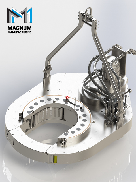
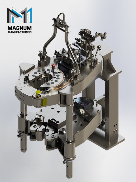
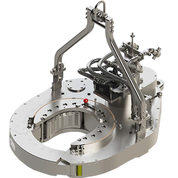
The 14-100 hydraulic power tong provides 100,000 ft-lb (135,600 N∙m) of torque capacity for running and pulling 7- to 14-in. casing. The tong has a unique gated rotary, a free-floating backup, and a hydraulic door interlock.
Our 14-50 high-torque casing tong provides 50,000 ft-lb (67,790 N∙m) of torque capacity for running and pulling 6 5/8- to 14-in. casing. The tong has a unique gated rotary, a free floating backup, and a hydraulic door interlock.
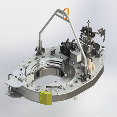
The 16-25 hydraulic casing tong provides 25,000 ft-lb (33,900 N∙m) of torque capacity for running and pulling 6 5/8- to 16-in. casing. The tong features a unique gated rotary and as many as seven contact points that create a positive grip without damaging the casing.
Rigged up without rig modifications, our 21-300 riser tong is the only tong capable of producing 300,000 ft-lb (406,746 N∙m) of continuous rotational torque in both makeup and breakout mode. The power it achieves in a compact size compares with a conventional 24-in. casing tong.
The 24-50 high-torque casing tong provides 50,000 ft-lb (67,790 N∙m) of torque capacity for running and pulling 10 3/4- to 24-in. casing. The tong features a unique gated rotary, a free-floating backup, and a hydraulic door interlock.
The 30-100 high-torque casing tong provides 100,000 ft-lb (135,600 N∙m) of torque capacity for running and pulling 16- to 30-in. casing. The tong features a unique gated rotary, a free-floating backup, and a hydraulic door interlock.
The 5.5-15 hydraulic tubing tong provides 15,000 ft-lb (20,340 N∙m) of torque capability for makeup and breakout of 1.66- to 5.5-in. tubing and premium or standard connections on corrosion‑resistant alloy tubulars. The tong features an ergonomic, lightweight design with a free-floating hydraulic backup.
The 7.6-30 hydraulic tubing tong provides 30,000 ft-lb (40,670 N∙m) of torque capability for makeup and breakout of 2 3/8- to 7 5/8-in. tubing and premium or standard connections on corrosion‑resistant alloy tubulars. The tong features an ergonomic, lightweight design with a free-floating hydraulic backup.
Our SpeedTork 8.0-70 tong provides torques up to 70,000 ft-lb (94,900 N∙m) and 360° rotation in makeup and breakout operations. It can torque drillpipe connections, drillstring components, drilling tools, packers, couplings, and valves.

Embodiments of the present invention generally relate to systems and methods for local hydraulic power generation on an electric tong. Description of the Related Art
Tongs are devices used on oil and gas rigs for gripping, clamping, spinning, and/or rotating tubular members, such as casing, drill pipe, drill collars, and coiled tubing (herein referred to collectively as tubulars and/or tubular strings). Tongs may be used to make-up or break-out threaded joints between tubulars. Tongs typically resemble large wrenches, and may sometime be referred to as power tongs, torque wrenches, spinning wrenches, and/or iron roughnecks. Tongs have typically used hydraulic power to provide sufficiently high torque to make-up or break-out threaded joints between tubulars. Such hydraulic tongs have suffered from the requirement of a hydraulic power generator on the rig floor, necessitating big hydraulic hoses connecting the hydraulic power generator to the tong, causing contamination concerns and excessive noise. Moreover, due to the distance from the power generator to the tong, hydraulic tongs have suffered from reliability issues and imprecise control of the torque.
Electric tongs have been proposed. For example, U.S. Pat. No. 9,453,377 suggests retrofitting a conventional hydraulic power tong with an electric motor. The electric motor would then be used to operate the power tong for rotating or spinning a tubular during make-up or break-out operations. A separate electric motor is proposed to actuate lift cylinders between the power tong and the backup tong. Another separate electric motor is proposed for applying clamping force to the backup tong. However, electric power supply for a tong might be insufficient when extreme forces are required. Moreover, the multiplicity of electric motors may be impractical when costs are an issue.
Local hydraulic power generation on an electric tong may provide improved handling, greater reliability, and increased safety and efficiency at reasonable costs. SUMMARY OF THE INVENTION
In an embodiment a tong system includes a power tong for spinning tubulars; a first electric motor functionally connected to the power tong; a plurality of hydraulic power consumers including a backup tong for clamping a tubular string; a second electric motor functionally connected to the plurality of hydraulic power consumers; and electronics to drive the first electric motor and the second electric motor.
In an embodiment, a tong system includes a power tong for spinning tubulars; a plurality of hydraulic power consumers including a backup tong for clamping a tubular string; an onboard electric motor; and a switchbox providing at least two configurations of the tong system: in a first configuration, the onboard electric motor drives the power tong but does not supply hydraulic power to the plurality of hydraulic power consumers; and in a second configuration, the onboard electric motor does not drive the power tong but does supply hydraulic power to at least one of the plurality of hydraulic power consumers.
In an embodiment, a tong system includes a backup tong for clamping a tubular string; an onboard electric motor; and an onboard hydraulic power unit coupled to the onboard electric motor to supply hydraulic power to the backup tong.
In an embodiment, a method of making-up tubulars includes arranging a tong system in a hydraulic power configuration; supplying hydraulic power to at least one of a plurality of hydraulic power consumers to position a tubular for make-up; arranging the tong system in a rotary drive configuration; supplying at least one of torque and rotation to a power tong; wherein an onboard electric motor of the tong system supplies the hydraulic power when the tong system is in the hydraulic power configuration, and the onboard electric motor supplies the at least one of torque and rotation when the tong system is in the rotary drive configuration. BRIEF DESCRIPTION OF THE DRAWINGS
FIG. 4 illustrates a tong system that is configured to switch electric power between a rotary drive configuration and a hydraulic power configuration.
In some embodiments, onboard electric motors may be beneficially utilized to supply large power densities that are controllable with a variable frequency drive. For example, the speed and/or torque of an electric motor may be controlled to reach a predefined target torque and/or to keep a predefined torque profile. The torque of the electric motor may be proportional to the current that is regulated electronically by a variable frequency drive, while the speed may be in phase with the generated frequency. In one embodiment, miniaturized, controllable electric motors may be mounted on the tong system (i.e., “onboard”). In some embodiments, the onboard electric motors may be capable of producing output in the range of about 2 kW/kg to about 5 kW/kg. In some embodiments, the onboard electric motors may be between about 8 kg and about 12 kg, for example, about 10 kg. In some embodiments, the onboard electric motor may be coupled to one or more of a reducing gear, another gear stage for low gear, and a flameproof housing. In some embodiments, these combined components may be between about 64 kg and about 96 kg, which may still be lighter than similar power provide by a hydraulic system.
As illustrated in FIG. 1, a tong system 100 suitable for use on oil and gas rigs generally includes a backup tong 110 for gripping and/or clamping the tubular string and a power tong 120 for spinning the tubular. The backup tong 110 may generally be below the power tong 120. The backup tong 110 clamps the tubular string to provide an opposing force to the torque applied to the tubular from power tong 120. Consequently, the backup tong 110 may be characterized as generally having high torque at low rpm requirements. The power tong 120 spins the tubular during make-up/break-out operations. Consequently, the power tong 120 may be characterized as generally having high torque at high rpm requirements. The tong system 100 may also include one or more lift actuators 130 (e.g., a linear actuator cylinder) for vertically positioning the backup tong 110. The tong system 100 may also include one or more door actuators 140 for controlling the tubular access door 145. In embodiments discussed below, tong system 100 also includes one or more of a hydraulic power unit 150, power electronics 160, and/or a switchbox 180, to provide local hydraulic power generation.
In some embodiments, the average power required to operate a power tong 120 during one work cycle may be less than 10% of the maximum power. For example, FIG. 2 illustrates a graph 200 of the maximum torque values vs. rotation speed for a 50 k ft lbf power tong 120 in low gear and in high gear. It should be appreciated that the power of the tong may be limited by the available power of the hydraulic supply and by physical layout. In the example of FIG. 2, the rated pressure (that results in the maximum torque) may be about 200 bar, and the maximum volume flow rate the tong may accept may be about 100 liter/minute. Therefore, the maximum power that the system may be capable of would be about 33.33 kW. As illustrated in FIG. 2, the power tong 120 may operate in low gear at region 210, generating torque of between about 20 k ft lbf and about 60 k ft lbf. With the power tong 120 in low gear, the tubular rotates at up to about 5 rpm. Therefore, the maximum power requirement in low gear is about:
The power tong 120 may operate in high gear at region 220, generating torque of between about 4 k ft lbf and about 10 k ft lbf. Therefore, the maximum power requirement in high gear is about:
Likewise, when operating in the high gear region 220, the power tong 120 may provide higher torque at lower rpm with similar maximum power requirements:
The examples from Equations 1-3 are upper values which are normally only demanded for a short period of time. During an entire make-up cycle of about 120 seconds, the average power is about 10% of the maximum power requirement. Therefore, with the maximum power required in low gear region 210 or in high gear region 220 being approximately 14.2 kW and 17.0 kW respectively, the average power required in either of these regions is 1.4 kW and 1.7 kW, respectively, which is less than about 10% of the maximum power of the system (33.33 kW), and a local battery may be capable of supplying the power for the power tong 120 without significantly increasing safety concerns (e.g., risks of excessive heat in the explosive atmosphere of an oil rig). For example, peak power may be supplied to power tong 120 by a lithium titanate or lithium iron phosphate battery. Such a battery may supply about 1.2 kW/kg to about 2.4 kW/kg without excessive heating.
FIG. 3 illustrates a graph 250 of the torque and rotation speed required over a typical make-up cycle for a power tong 120. At the beginning of the make-up cycle, in region 260 (e.g., about first 5 seconds), the rotor may be slowly rotated in low gear to engage the tubular threads and confirm that the threading has engaged correctly. During the middle of the make-up cycle, in region 270, the rotor (now in high gear) speeds-up to the maximum speed (for example, as defined for this tubular type by the drilling contractor). The high rpm may be maintained for about 15 seconds until a reference torque is reached. For example, the reference torque may be selected to stop the tong well before the tubular shoulders engage. When the reference shoulder torque is reached, the power tong 120 is switched back to low gear. In region 280, the make-up may be done smoothly and/or continuously in low gear (e.g. for about the next 8 seconds). Lastly, the threads are secured in region 290 as indicated by rapidly increasing torque and decreasing rpm. The required power, which is the product of torque and turns, is normally less than half of the maximum power. Furthermore, the complete work cycle is more than 2 minutes, because bringing in another pipe, stabbing-in, and finally lowering the string into the well takes most of the time. Considering this, the average power is about 10% of the maximum power of the tong.
Electric power supply for a tong might be insufficient when extreme forces are required. Moreover, the multiplicity of electric motors may be impractical when costs are an issue. Therefore, a source of local hydraulic power is proposed. As illustrated in FIG. 1, tong system 100 includes local hydraulic power generation. As previously discussed, the tong system 100 includes a backup tong 110, a power tong 120, and one or more lift actuators 130. Tong system 100 also includes a hydraulic power unit 150. In some embodiments, hydraulic power for the backup tong 110 may be supplied by the hydraulic power unit 150. For example, the backup tong 110 may utilize high force to clamp cylinders to clamp the tubular string and thereby counterbalance the high torque of the power tong 120. In some embodiments, hydraulic power for the lift actuators 130 may be supplied by the hydraulic power unit 150. For example, the lift actuators 130 may utilize high force to vertically position (e.g., raise or lower) the backup tong 110 while it clamps the tubular string. In some embodiments, the volume of the hydraulic power unit 150 may be less than (e.g., about 10% of) that of conventional hydraulic power units which had been located proximate the rig floor. For example, a rig floor hydraulic power unit that is capable of producing up to about 35 kW-about 40 kW may have a volume of about 400 liters, while hydraulic power unit 150 may have a volume of between about 30 liters and about 40 liters, or in some embodiments less than about 50 liters. Hydraulic power unit 150 may include a tank with a submerged motor and a dual stage pump. Hydraulic power unit 150 may include a tank with a submerged motor and a pump with a booster. Hydraulic power unit 150 may include a tank with a submerged motor with a variable frequency drive. Hydraulic power unit 150 may include a tank with a submerged small motor with a hydraulic accumulator. In some embodiments, the hydraulic power unit 150 may supply power so that the cylinders (e.g., clamp cylinders of backup tong 110, lift cylinders of lift actuators 130) have fast action while having maximum pressure. Exemplary hydraulic power units 150 may include compact hydraulic power packs wherein the motor shaft of the electric motor also acts as the pump shaft.
In some embodiments, the hydraulic power unit may be powered by an onboard electric motor. This may allow for a single electric motor to be utilized both for the power tong and for backup tong. For example, a switchbox may decouple the rotor of the power tong when the hydraulic pump is activated. FIG. 4 illustrates a tong system 400 that can switch between a rotary drive configuration and a hydraulic power configuration. As illustrated, tong system 400 includes a hydraulic power unit 450 that includes an accumulator 451 and a pump 452 (which may include a reservoir tank (not shown)). Tong system 400 also includes an onboard electric motor 453. An exemplary onboard electric motor 453 may be a low voltage motor with integrated electronics. Hydraulic power unit 450 may supply hydraulic power to one or more hydraulic power consumers, such as the backup tong 410, the lift actuators 430, and the door actuators 440. Onboard electric motor 453 may also and/or alternatively supply torque and/or rotation to power tong 420. For example, switchbox 480 may switch the output of onboard electric motor 453 between the pump 452 and drivetrain 425 (e.g., a gearbox and a rotor) for power tong 420. In some embodiments, switchbox 480 may be configured to switch the output of onboard electric motor 453 to pump 452 to store hydraulic power in accumulator 451 while one or more of the power tong 420, backup tong 410, lift actuators 430, and/or door actuators 440 are inactive. In some embodiments, switchbox 480 may be configured to switch the output of onboard electric motor 453 to pump 452 to directly drive one or more of the backup tong 410, lift actuators 430, and/or door actuators 440. In some embodiments, tong system 400 may not receive hydraulic power from an external source (e.g., a hydraulic power unit on the rig floor). Specifically, backup tong 410 may only receive hydraulic power from local hydraulic power unit 450.
In some embodiments, onboard electric motor 453 may be selected to supply either (a) sufficient torque and rotation to power tong 420


 8613371530291