
automated power tong us patent for sale
March 17, 1970 J. H. WILSON AUTOMATED PIPE TONGS l9 Sheets-Sheet 5 Filed May 1, 1967 VIIIIII Rm 5 .m a. m :W m /m mw u H hw m. 7 m p uildli|||J||1||i|||||||J |||J" W m w M 8 y 1 0 mm mm 00 mm March 17, 1970 J. H. WILSON AUTOMATED PIPE I"ONGS 19 Sheets-Sheet 4 Filed May 1, 1967 E m mF 1176 19/9/67 W/LFU/V INVENTOR.
BY W 51/15 105%! Ill March 17, 1970 J. H. WILSON AUTOMATED PIPE TONGS l9 Sheets-Sheet 5 Filed May 1, 1967 March 17, 1970 J. H. WILSON AUTOMATED PIPE TON-GS 19 Sheets-Sheet 6 Filed May 1, 1967 mww IN VENTOR.
AUTOMATED PIPE TONGS 19 Sheets-Sheet 10 Filed May 1, 1967 FIR JOHN HART WILSON INVENTOR ,L umv NOm Gm? QM Oh HIS AGENT March 17, 1970 J. H. WILSON AUTOMATED PIPE TONGS 19 Sheets-Sheet 11 Filed May 1, 1967 mN Wm (D Q JOHN HART WILSON INVENTOR.
AUTOMATED PIPE TONGS Filed May 1, 1967 19 Sheets-Sheet l5 mvsmom JOHN HART WILSON- March 17, 1970 J. H. WILSON AUTOMATED PIPE TONGS 19 Sheets-Sheet 16 Filed May 1, 1967 INVENTOR.
HIS AGENT March 17, 1970 J. H. WILSON AUTOMATED PIPE TONGS l9 Sheets-Sheet 18 Filed May 1, 1967 INVENTOR OHN HART W I LSQN HIS AGENT on mun u% 2m 3w! m9 n3 N3 w w mum mm 93 I r 0 r T an 03 com m on o ow wfi Q8. 02. N2. l gov wo dwown J r|..) 0%. 8 3 in. 2
US. Cl. 81-5734 Claims ABSTRACT OF THE DISCLOSURE Automated pipe tongs for making up or breaking out drill stem or pipe, such as used in conjunction with a drilling rig, which tongs are moved into and away from operating position on a wheeled carrier. The various operations of tongs are actuated by fluid cylinders, which fluid cylinders are programmed by a rotary cam programming control mechanism, to cause sequential action of certain cylinders, both for the opening and for closing the tongs and for moving the handle of one of the tongs arcuately to make up or break out drill stem or pipe. Two or more cams may be programmed to operate simultaneously, with the same operations being repeated each time the programming mechanism makes one complete cycle. The present programming device is so constructed as to stop when one cycle is completed. Provisions are made for stopping the programming mechanism at any point within the cycle and for manually operating valves to perform any phase of the operation. Further valves are provided to selectively render any portion of the operation inoperative. Further provisions are made to enable the entire programmed cam shaft to be removed and another programmed cam shaft installed to perform diflerent operations.
This invention relates to pipe tongs to be used for gripping pipe to enable pipe to be screwed together or unscrewed, and more particularly to power actuated pipe tongs which may be remotely controlled so the individual operating the tongs is relieved of openin and closing the tongs, of engaging the tongs on the pipe and of removing the tongs therefrom, as well as of moving the lever of the tongs arcuately about the axis of the pipe when the tongs are engaged on the pipe.
Various tongs have been provided heretofore which are operated both manually and by power, however, for the most part, these tongs had to be manually controlled to engage the pipe and manually swung out of engagement when the pipe was sufiiciently tightened.
The present tongs are so constructed that a single operator may operate both the tongs to enable automatic or mechanical engagement thereof with the pipe, from a non-operating position to an operating position, and then, after the tongs are in position to engage the pipe, power is used to close the tongs in gripping relation around the pipe. Furthermore, the apparatus for handling the tongs is actuated by fluid power, which rotates the pipe in either direction as desired, while the back-up tong is maintained in engaged gripping relation with a complementary joint of pipe so as to enable the entire work to be performed by remote control, and without danger to the workmen, as has been the case heretofore, in most instances, in the use of power actuated tongs.
The present tongs are used primarily in combination With a derrick, mast or the like, however, they are subject to adaptation to any phase of screwing together or unscrewing pipe, merely by changing the mounting to accommodate the particular pipe screwing up or unscrewing job to be done. The present tong is primarily used with drill pipe in the drilling of oil wells, which pipe consists of threaded joints, to enable the coupling of lengths of pipe together in the form of a drill stem, which may extend several hundred or several thousand feet into the earth strata to perform the operation of drilling an oil well by the rotary drilling method. In performing this drilling operation, it is desirable to have all pipe joints tightened securely and accurately, but not tightened to such extent as to cause the threads to gall or to strip.
An object of this invention is to provide power actuated tongs which may be swung into place around axially aligned lengths of pipe to enable the making up or breaking out of the threaded joints connecting lengths of pipe in end-to-end relation.
Another object of this invention is to provide a power actuated tong in which all control operations may be performed from a remote station, to enable the tongs to be guided onto the pipe, so as to surround lengths of axially aligned pipe to screw the pipe together, or to unscrew the lengths of pipe without manual assistance from the operator.
Still another object of the invention is to provide a power actuated tong for gripping lengths of pipe to be screwed together, wherein a cam and lever, operated under fluid pressure, closes the jaws of the tongs around the pipe in gripping relation to give a mechanical advantage.
Still another object of the invention is to provide a side opening tong which may be moved onto or off of a pipe from a side thereof without the necessity of having to draw the pipe through the tong.
Still another object of the invention is to provide a suspension system for a pair of tongs, whereby they can be moved into or out of engagement with a pair of axially aligned lengths of pipe in the same path each time the tongs are positioned thereon, thereby making it unnecessary for manual guidance of the tongs into the correct position.
Still another object of the invention is to provide a power actuated tong which may be readily regulated to take care of worn pipe or pipe of diflerent diameters.
Still a further object of the invention is to provide tong adjustment means to enable the attachment of the tongs to the pipe in such manner as to swing the tongs into place around axially aligned lengths of pipe in the same relation each time.
Still another object of the invention is to provide fluid power actuated cylinder means to rotate at least one of the tongs through an arcuate travel each time the fluid actuated cylinder plunger is reciprocated.
Still another object of the invention is to provide a fluid control system for controlling the thrust exerted by the respective fluid actuated cylinders so as to prevent crushing of the pipe or twisting the pipe in two.
Still a further object of the invention is to provide a tong mounting system to enable the tongs to be moved into engagement with a pair of axially aligned lengths of pipe and be moved out of engagement with the pipe and out of the work area when the screwing or unscrewing operation has been performed.
Magnum Manufacturing is a team of experienced casing running engineers and industry-leading professionals tired of working with existing substandard equipment. We have spent decades developing equipment to the highest industry standards, and we personally have been using the equipment we’ve developed. After 30+ years of partnering with a leading American TRS company to ensure optimal performance, we are prepared to stake our reputation on Performance, Longevity, & Safety.
Magnum Manufacturing is a team of experienced casing running engineers and industry-leading professionals tired of working with existing substandard equipment. We have spent decades developing equipment to the highest industry standards, and we personally have been using the equipment we’ve developed. After 30+ years of partnering with a leading American TRS company to ensure optimal performance, we are prepared to stake our reputation on Performance, Longevity, & Safety.
Embodiments of the present invention generally relate to systems and methods for local hydraulic power generation on an electric tong. Description of the Related Art
Tongs are devices used on oil and gas rigs for gripping, clamping, spinning, and/or rotating tubular members, such as casing, drill pipe, drill collars, and coiled tubing (herein referred to collectively as tubulars and/or tubular strings). Tongs may be used to make-up or break-out threaded joints between tubulars. Tongs typically resemble large wrenches, and may sometime be referred to as power tongs, torque wrenches, spinning wrenches, and/or iron roughnecks. Tongs have typically used hydraulic power to provide sufficiently high torque to make-up or break-out threaded joints between tubulars. Such hydraulic tongs have suffered from the requirement of a hydraulic power generator on the rig floor, necessitating big hydraulic hoses connecting the hydraulic power generator to the tong, causing contamination concerns and excessive noise. Moreover, due to the distance from the power generator to the tong, hydraulic tongs have suffered from reliability issues and imprecise control of the torque.
Electric tongs have been proposed. For example, U.S. Pat. No. 9,453,377 suggests retrofitting a conventional hydraulic power tong with an electric motor. The electric motor would then be used to operate the power tong for rotating or spinning a tubular during make-up or break-out operations. A separate electric motor is proposed to actuate lift cylinders between the power tong and the backup tong. Another separate electric motor is proposed for applying clamping force to the backup tong. However, electric power supply for a tong might be insufficient when extreme forces are required. Moreover, the multiplicity of electric motors may be impractical when costs are an issue.
Local hydraulic power generation on an electric tong may provide improved handling, greater reliability, and increased safety and efficiency at reasonable costs. SUMMARY OF THE INVENTION
In an embodiment a tong system includes a power tong for spinning tubulars; a first electric motor functionally connected to the power tong; a plurality of hydraulic power consumers including a backup tong for clamping a tubular string; a second electric motor functionally connected to the plurality of hydraulic power consumers; and electronics to drive the first electric motor and the second electric motor.
In an embodiment, a tong system includes a power tong for spinning tubulars; a plurality of hydraulic power consumers including a backup tong for clamping a tubular string; an onboard electric motor; and a switchbox providing at least two configurations of the tong system: in a first configuration, the onboard electric motor drives the power tong but does not supply hydraulic power to the plurality of hydraulic power consumers; and in a second configuration, the onboard electric motor does not drive the power tong but does supply hydraulic power to at least one of the plurality of hydraulic power consumers.
In an embodiment, a tong system includes a backup tong for clamping a tubular string; an onboard electric motor; and an onboard hydraulic power unit coupled to the onboard electric motor to supply hydraulic power to the backup tong.
In an embodiment, a method of making-up tubulars includes arranging a tong system in a hydraulic power configuration; supplying hydraulic power to at least one of a plurality of hydraulic power consumers to position a tubular for make-up; arranging the tong system in a rotary drive configuration; supplying at least one of torque and rotation to a power tong; wherein an onboard electric motor of the tong system supplies the hydraulic power when the tong system is in the hydraulic power configuration, and the onboard electric motor supplies the at least one of torque and rotation when the tong system is in the rotary drive configuration. BRIEF DESCRIPTION OF THE DRAWINGS
So that the manner in which the above recited features of the present invention can be understood in detail, a more particular description of the invention, briefly summarized above, may be had by reference to embodiments, some of which are illustrated in the appended drawings. It is to be noted, however, that the appended drawings illustrate only typical embodiments of this invention and are therefore not to be considered limiting of its scope, for the invention may admit to other equally effective embodiments.
FIG. 4 illustrates a tong system that is configured to switch electric power between a rotary drive configuration and a hydraulic power configuration.
In some embodiments, onboard electric motors may be beneficially utilized to supply large power densities that are controllable with a variable frequency drive. For example, the speed and/or torque of an electric motor may be controlled to reach a predefined target torque and/or to keep a predefined torque profile. The torque of the electric motor may be proportional to the current that is regulated electronically by a variable frequency drive, while the speed may be in phase with the generated frequency. In one embodiment, miniaturized, controllable electric motors may be mounted on the tong system (i.e., “onboard”). In some embodiments, the onboard electric motors may be capable of producing output in the range of about 2 kW/kg to about 5 kW/kg. In some embodiments, the onboard electric motors may be between about 8 kg and about 12 kg, for example, about 10 kg. In some embodiments, the onboard electric motor may be coupled to one or more of a reducing gear, another gear stage for low gear, and a flameproof housing. In some embodiments, these combined components may be between about 64 kg and about 96 kg, which may still be lighter than similar power provide by a hydraulic system.
As illustrated in FIG. 1, a tong system 100 suitable for use on oil and gas rigs generally includes a backup tong 110 for gripping and/or clamping the tubular string and a power tong 120 for spinning the tubular. The backup tong 110 may generally be below the power tong 120. The backup tong 110 clamps the tubular string to provide an opposing force to the torque applied to the tubular from power tong 120. Consequently, the backup tong 110 may be characterized as generally having high torque at low rpm requirements. The power tong 120 spins the tubular during make-up/break-out operations. Consequently, the power tong 120 may be characterized as generally having high torque at high rpm requirements. The tong system 100 may also include one or more lift actuators 130 (e.g., a linear actuator cylinder) for vertically positioning the backup tong 110. The tong system 100 may also include one or more door actuators 140 for controlling the tubular access door 145. In embodiments discussed below, tong system 100 also includes one or more of a hydraulic power unit 150, power electronics 160, and/or a switchbox 180, to provide local hydraulic power generation.
In some embodiments, the average power required to operate a power tong 120 during one work cycle may be less than 10% of the maximum power. For example, FIG. 2 illustrates a graph 200 of the maximum torque values vs. rotation speed for a 50 k ft lbf power tong 120 in low gear and in high gear. It should be appreciated that the power of the tong may be limited by the available power of the hydraulic supply and by physical layout. In the example of FIG. 2, the rated pressure (that results in the maximum torque) may be about 200 bar, and the maximum volume flow rate the tong may accept may be about 100 liter/minute. Therefore, the maximum power that the system may be capable of would be about 33.33 kW. As illustrated in FIG. 2, the power tong 120 may operate in low gear at region 210, generating torque of between about 20 k ft lbf and about 60 k ft lbf. With the power tong 120 in low gear, the tubular rotates at up to about 5 rpm. Therefore, the maximum power requirement in low gear is about:
The power tong 120 may operate in high gear at region 220, generating torque of between about 4 k ft lbf and about 10 k ft lbf. Therefore, the maximum power requirement in high gear is about:
Likewise, when operating in the high gear region 220, the power tong 120 may provide higher torque at lower rpm with similar maximum power requirements:
The examples from Equations 1-3 are upper values which are normally only demanded for a short period of time. During an entire make-up cycle of about 120 seconds, the average power is about 10% of the maximum power requirement. Therefore, with the maximum power required in low gear region 210 or in high gear region 220 being approximately 14.2 kW and 17.0 kW respectively, the average power required in either of these regions is 1.4 kW and 1.7 kW, respectively, which is less than about 10% of the maximum power of the system (33.33 kW), and a local battery may be capable of supplying the power for the power tong 120 without significantly increasing safety concerns (e.g., risks of excessive heat in the explosive atmosphere of an oil rig). For example, peak power may be supplied to power tong 120 by a lithium titanate or lithium iron phosphate battery. Such a battery may supply about 1.2 kW/kg to about 2.4 kW/kg without excessive heating.
FIG. 3 illustrates a graph 250 of the torque and rotation speed required over a typical make-up cycle for a power tong 120. At the beginning of the make-up cycle, in region 260 (e.g., about first 5 seconds), the rotor may be slowly rotated in low gear to engage the tubular threads and confirm that the threading has engaged correctly. During the middle of the make-up cycle, in region 270, the rotor (now in high gear) speeds-up to the maximum speed (for example, as defined for this tubular type by the drilling contractor). The high rpm may be maintained for about 15 seconds until a reference torque is reached. For example, the reference torque may be selected to stop the tong well before the tubular shoulders engage. When the reference shoulder torque is reached, the power tong 120 is switched back to low gear. In region 280, the make-up may be done smoothly and/or continuously in low gear (e.g. for about the next 8 seconds). Lastly, the threads are secured in region 290 as indicated by rapidly increasing torque and decreasing rpm. The required power, which is the product of torque and turns, is normally less than half of the maximum power. Furthermore, the complete work cycle is more than 2 minutes, because bringing in another pipe, stabbing-in, and finally lowering the string into the well takes most of the time. Considering this, the average power is about 10% of the maximum power of the tong.
Electric power supply for a tong might be insufficient when extreme forces are required. Moreover, the multiplicity of electric motors may be impractical when costs are an issue. Therefore, a source of local hydraulic power is proposed. As illustrated in FIG. 1, tong system 100 includes local hydraulic power generation. As previously discussed, the tong system 100 includes a backup tong 110, a power tong 120, and one or more lift actuators 130. Tong system 100 also includes a hydraulic power unit 150. In some embodiments, hydraulic power for the backup tong 110 may be supplied by the hydraulic power unit 150. For example, the backup tong 110 may utilize high force to clamp cylinders to clamp the tubular string and thereby counterbalance the high torque of the power tong 120. In some embodiments, hydraulic power for the lift actuators 130 may be supplied by the hydraulic power unit 150. For example, the lift actuators 130 may utilize high force to vertically position (e.g., raise or lower) the backup tong 110 while it clamps the tubular string. In some embodiments, the volume of the hydraulic power unit 150 may be less than (e.g., about 10% of) that of conventional hydraulic power units which had been located proximate the rig floor. For example, a rig floor hydraulic power unit that is capable of producing up to about 35 kW-about 40 kW may have a volume of about 400 liters, while hydraulic power unit 150 may have a volume of between about 30 liters and about 40 liters, or in some embodiments less than about 50 liters. Hydraulic power unit 150 may include a tank with a submerged motor and a dual stage pump. Hydraulic power unit 150 may include a tank with a submerged motor and a pump with a booster. Hydraulic power unit 150 may include a tank with a submerged motor with a variable frequency drive. Hydraulic power unit 150 may include a tank with a submerged small motor with a hydraulic accumulator. In some embodiments, the hydraulic power unit 150 may supply power so that the cylinders (e.g., clamp cylinders of backup tong 110, lift cylinders of lift actuators 130) have fast action while having maximum pressure. Exemplary hydraulic power units 150 may include compact hydraulic power packs wherein the motor shaft of the electric motor also acts as the pump shaft.
In some embodiments, the hydraulic power unit may be powered by an onboard electric motor. This may allow for a single electric motor to be utilized both for the power tong and for backup tong. For example, a switchbox may decouple the rotor of the power tong when the hydraulic pump is activated. FIG. 4 illustrates a tong system 400 that can switch between a rotary drive configuration and a hydraulic power configuration. As illustrated, tong system 400 includes a hydraulic power unit 450 that includes an accumulator 451 and a pump 452 (which may include a reservoir tank (not shown)). Tong system 400 also includes an onboard electric motor 453. An exemplary onboard electric motor 453 may be a low voltage motor with integrated electronics. Hydraulic power unit 450 may supply hydraulic power to one or more hydraulic power consumers, such as the backup tong 410, the lift actuators 430, and the door actuators 440. Onboard electric motor 453 may also and/or alternatively supply torque and/or rotation to power tong 420. For example, switchbox 480 may switch the output of onboard electric motor 453 between the pump 452 and drivetrain 425 (e.g., a gearbox and a rotor) for power tong 420. In some embodiments, switchbox 480 may be configured to switch the output of onboard electric motor 453 to pump 452 to store hydraulic power in accumulator 451 while one or more of the power tong 420, backup tong 410, lift actuators 430, and/or door actuators 440 are inactive. In some embodiments, switchbox 480 may be configured to switch the output of onboard electric motor 453 to pump 452 to directly drive one or more of the backup tong 410, lift actuators 430, and/or door actuators 440. In some embodiments, tong system 400 may not receive hydraulic power from an external source (e.g., a hydraulic power unit on the rig floor). Specifically, backup tong 410 may only receive hydraulic power from local hydraulic power unit 450.
In some embodiments, onboard electric motor 453 may be selected to supply either (a) sufficient torque and rotation to power tong 420, as illustrated by the work cycle graphs of FIGS. 2-3, or (b) sufficient power to drive hydraulic power unit 450 between power tong work cycles, but not both at the same time, and no more than the maximum of the two. For example a DYNAX 60i motor includes integrated electronics while still being only about 14 kg. Consequently, onboard electric motor 453 may be small enough to not pose excessive risks (e.g., heat, noise, fuel consumption) in the rig environment.
Tong system 400 of FIG. 4 may also include electronics 460. The electronics 460 may include a charger 462, a programmable logic controller 464, a battery 466, and an inverter 468. Electronics 460 and/or inverter 468 may function as a variable frequency drive for onboard electric motor 453. Battery 466 may be a lithium iron phosphate battery and/or a lithium titanate battery. An exemplary battery 466 may be a 14 Ah Prismatic Pouch Cell, available from A123 Systems of Livonia, Mich. The battery may be, for example, between about 5 kg to 10 kg. The battery 466 may be contained in a flameproof housing. It is believed that no ATEX standard currently exists for batteries on tong systems, and further testing may be needed. Onboard electric motor 453 may be driven and/or controlled by electronics 460. For example, the torque of onboard electric motor 453 may be proportional to the current coming from the inverter 468. Likewise, the speed of onboard electric motor 453 may be in phase with the frequency of the current coming from the inverter 468. Onboard electric motor 453 may supply torque to power tong 420 in order to make-up to tubulars to a precise target torque while maintaining this torque for some time.
In some embodiments, onboard electric motor 453 and/or electronics 460 may be enclosed in a flameproof housing. For example, the flameproof housing may meet ATEX standards for class 1, zone 1, division 1. In some embodiments, the flameproof housing may be aluminum. In some embodiments, onboard electric motor 453 may be integrated with one or more components of electronics 460.
In some embodiments, programmable logic controller 464 may switch power supply to the consumers. For example, the battery 466 may alternatively charge and discharge, the onboard electric motor 453 may switch between the drivetrain 425 and the hydraulic power unit 450, and the sources of hydraulic power may be the pump 452 and/or the accumulator 451. At times during operations, each of backup tong 410, lift actuators 430, and door actuators 440 may be powered by one or more of the sources of hydraulic power. The programmable logic controller 464 may determine which power source supplies which consumer at any point in time during operations.
In some embodiments, the hydraulic power unit may be powered by a dedicated onboard electric motor. This may allow for a dedicated electric motor to be utilized for the power tong and a smaller, dedicated electric motor to be utilized for the hydraulic power unit. FIG. 5 illustrates a tong system 500 with separate, dedicated electric motors for the rotary drive configuration and the hydraulic power configuration. As illustrated, tong system 500 includes a hydraulic power unit 550 that includes an accumulator 551 and a pump 552 (which may include a reservoir tank (not shown)). Tong system 500 also includes a first electric motor 523 for the power tong 520, and a second electric motor 553 for the hydraulic power unit 550. The second electric motor 553 may be smaller than the first electric motor 523. In some embodiments, the second electric motor 553 may be about 1/10 of the size of the first electric motor 523. Both the first electric motor 523 and the second electric motor 553 may be otherwise similar to onboard electric motor 453. Hydraulic power unit 550 may supply hydraulic power to one or more hydraulic power consumers, such as the backup tong 510, the lift actuators 530, and the door actuators 540. First electric motor 523 may supply torque and/or rotation to power tong 520. Output of first electric motor 523 may supply power to drivetrain 525 (e.g., a gearbox and a rotor) for power tong 520. In some embodiments, output of second electric motor 553 may supply power to pump 552 to store hydraulic power in accumulator 551 while one or more of the backup tong 510, lift actuators 530, and/or door actuators 540 are inactive. In some embodiments, the output of second electric motor 553 may supply power to pump 552 to directly drive one or more of the backup tong 510, lift actuators 530, and/or door actuators 540. In some embodiments, while the second electric motor 553 and/or the pump 552 are inactive, the accumulator 551 may supply power to directly drive one or more of the backup tong 510, lift actuators 530, and/or door actuators 540. For example, pressure switch 581 may shut off second electric motor 553 when a target pressure in accumulator 551 has been reached. In some embodiments, tong system 500 may not receive hydraulic power from an external source (e.g., a hydraulic power unit on the rig floor). Specifically, backup tong 510 may only receive hydraulic power from local hydraulic power unit 550.
In some embodiments, first electric motor 523 may be selected to supply sufficient torque and rotation to power tong 520, as illustrated by the work cycle graphs of FIGS. 2-3. In some embodiments, second electric motor 553 may be selected to supply sufficient power to drive hydraulic power unit 550 between power tong work cycles. Consequently, first electric motor 523 and/or second electric motor 553 may be small enough to not pose excessive risks (e.g., heat, noise, fuel consumption) in the rig environment.
Tong system 500 of FIG. 5 may also include electronics 560. The electronics 560 may include a charger 562, a programmable logic controller 564, a battery 566, and an inverter 568. Electronics 560 may be configured similar to electronics 460 and may function similar thereto. First electric motor 523 may be driven and/or controlled by electronics 560. For example, the torque of first electric motor 523 may be proportional to the current coming from the inverter 568. Likewise, the speed of first electric motor 523 may be in phase with the frequency of the current coming from the inverter 568. First electric motor 523 may supply torque to power tong 520 in order to make-up to tubulars to a precise target torque while maintaining this torque for some time.
Second electric motor 553 may be controlled by electronics 560. In some embodiments, programmable logic controller 564 may control power supply to the consumers. For example, the sources of hydraulic power may be the pump 552 (driven by the second electric motor 553) and/or the accumulator 551. At times during operations, each of backup tong 510, lift actuators 530, and door actuators 540 may be powered by one or more of the sources of hydraulic power. The programmable logic controller 564 may determine which power source supplies which consumer at any point in time during operations. For example, the programmable logic controller 564 may determine a target pressure for accumulator 551. Pressure switch 581 may shut off second electric motor 553 when the target pressure in accumulator 551 has been reached.
An exemplary make-up cycle 600 is illustrated in FIG. 6. The illustrated make-up cycle 600 is applicable to tong system 400, and a similar make-up cycle could be envisioned for tong system 500. Initially, in region 610, hydraulic power is supplied to the door actuator 440 to open the tubular access door 145 and allow for stabbing-in of new tubular. Accumulator 451 and/or pump 452 may supply hydraulic power to door actuator 440. Switchbox 480 may, therefore, be set to power hydraulic power unit 450 with onboard electric motor 453 during this initial region 610. The amount of hydraulic power 615 supplied is relatively low, so the battery 466 may charge (positive current 625) during region 610. In region 620, lift actuators 430 may vertically position the backup tong 410. Accumulator 451 and/or pump 452 may supply hydraulic power to lift actuators 430, and switchbox 480 may remain set to power hydraulic power unit 450 with onboard electric motor 453 during region 620. The amount of hydraulic power 615 supplied is sufficiently high to cause battery 466 to discharge (negative current 625). In region 630, backup tong 410 may clamp the tubular. Accumulator 451 and/or pump 452 may supply hydraulic power to backup tong 410, and switchbox 480 may remain set to power hydraulic power unit 450 with onboard electric motor 453 during region 630. As backup tong 410 engages and securely clamps the tubular, the hydraulic power 615 increases, causing the battery 466 to cycle from charging to discharging (positive to negative current 625). Clamping force 635 is initially constant during region 630, increasing to the endpoint for backup tong 410 at the end of region 630. In region 640, door actuator 440 may close the tubular access door 145 as backup tong 410 continues to securely clamp the tubular. Accumulator 451 and/or pump 452 may supply hydraulic power to door actuators 440 and backup tong 410, and switchbox 480 may remain set to power hydraulic power unit 450 with onboard electric motor 453 during region 640. The clamping force 635 is essentially constant during region 640. Throughout regions 610-640, onboard electric motor 453 has zero torque 645 and rotation speed 655.
The exemplary make-up cycle 600 continues from region 640 to region 650 wherein switchbox 480 switches the onboard electric motor 453 from supplying power to the hydraulic power unit 450 to the drivetrain 425 of power tong 420. Hydraulic power 615 from onboard electric motor 453, therefore, remains at zero in region 650 through the middle of region 680. The relatively constant clamping force 635 of backup tong 410 may be maintained by the accumulator 451. In some embodiments, a brace may be applied to hold the backup tong 410 in the clamped position, thereby maintaining the relatively constant clamping force 635 without hydraulic power from the accumulator 451 or pump 452. In some embodiments, a valve may be closed to hold pressure in the cylinder(s) of backup tong 410, thereby maintaining the relatively constant clamping force 635 without hydraulic power (pressure or flow) from the accumulator 451 or pump 452.
In region 650, onboard electric motor 453 initially drives drivetrain 425 with low torque 645 and low rotation speed 655 as tubular threading is engaged. Torque 645 may be increased as threading is confirmed. Current 625 may cause the battery 466 to go from charging to discharging as torque 645 increases. In region 660, onboard electric motor 453 may operate drivetrain 425 in high gear to spin-in the tubular. The onboard electric motor 453 may initially have zero torque 645 and rotation speed 655 while shifting gears. Current 625 may initially charge battery 466 until higher torques 645 cause the battery to discharge. The spin-in of region 660 may continue at a relatively constant rotation speed 655 until a reference torque 645 is reached. In region 670, onboard electric motor 453 may operate drivetrain 425 in low gear to make-up the connection to a target torque 645. By shifting gears, the rotation speed 655 of onboard electric motor 453 in region 670 may be similar to that of region 660. The ongoing clamping force 635, rotation speed 655, and increasing torque 645 causes the current 625 to be negative (battery 466 discharging) during much of region 670.
The exemplary make-up cycle 600 concludes in regions 680 and 690, as the threaded connection now couples the tubular to the tubular string. Power tong 420 is detached from the tubular early in region 680, requiring a relatively small amount of torque 645 and rotation speed 655 from onboard electric motor 453. Switchbox 480 then switches the onboard electric motor 453 to the hydraulic power unit 450. The door actuators 440 may open the tubular access door 145 to release the tubular, drawing a relatively low amount of hydraulic power 615. Battery 466 may charge with positive current 625 during region 680. Lastly, in region 690, backup tong 410 releases the tubular. As clamping force 635 ceases, current 625 may charge the battery 466 until it is fully charged.
In an embodiment a tong system includes a power tong for spinning tubulars; a first electric motor functionally connected to the power tong; a plurality of hydraulic power consumers including a backup tong for clamping a tubular string; a second electric motor functionally connected to the plurality of hydraulic power consumers; and electronics to drive the first electric motor and the second electric motor.
In one or more embodiments disclosed herein, the plurality of hydraulic power consumers comprises at least one of a lift actuator and a door actuator.
In one or more embodiments disclosed herein, the first electric motor couples to the power tong through a drivetrain having a low gear and a high gear.
In one or more embodiments disclosed herein, the tong system also includes a pump and an accumulator, wherein the second electric motor supplies hydraulic power with the pump.
In one or more embodiments disclosed herein, the tong system also includes a pressure switch to determine whether the pump or the accumulator supplies hydraulic power to at least one of the plurality of hydraulic power consumers.
In an embodiment, a tong system includes a power tong for spinning tubulars; a plurality of hydraulic power consumers including a backup tong for clamping a tubular string; an onboard electric motor; and a switchbox providing at least two configurations of the tong system: in a first configuration, the onboard electric motor drives the power tong but does not supply hydraulic power to the plurality of hydraulic power consumers; and in a second configuration, the onboard electric motor does not drive the power tong but does supply hydraulic power to at least one of the plurality of hydraulic power consumers.
In one or more embodiments disclosed herein, the plurality of hydraulic power consumers comprises at least one of a lift actuator and a door actuator.
In one or more embodiments disclosed herein, in the first configuration, the onboard electric motor couples to the power tong through a drivetrain having a low gear and a high gear.
In one or more embodiments disclosed herein, the tong system also includes a pump and an accumulator, wherein, in the second configuration, the onboard electric motor supplies hydraulic power with the pump.
In one or more embodiments disclosed herein, in the first configuration, the accumulator supplies hydraulic power to at least one of the plurality of hydraulic power consumers.
In one or more embodiments disclosed herein, the tong system also includes electronics, wherein, in the first configuration, at least one of a torque and a speed of the onboard electric motor is controlled by the electronics.
In an embodiment, a tong system includes a backup tong for clamping a tubular string; an onboard electric motor; and an onboard hydraulic power unit coupled to the onboard electric motor to supply hydraulic power to the backup tong.
In one or more embodiments disclosed herein, the tong system also includes a pressure switch to determine whether the pump or the accumulator supplies hydraulic power to the backup tong.
In an embodiment, a method of making-up tubulars includes arranging a tong system in a hydraulic power configuration; supplying hydraulic power to at least one of a plurality of hydraulic power consumers to position a tubular for make-up; arranging the tong system in a rotary drive configuration; supplying at least one of torque and rotation to a power tong; wherein an onboard electric motor of the tong system supplies the hydraulic power when the tong system is in the hydraulic power configuration, and the onboard electric motor supplies the at least one of torque and rotation when the tong system is in the rotary drive configuration.
In one or more embodiments disclosed herein, the onboard electric motor does not supply hydraulic power when the tong system is in the rotary drive configuration, and the onboard electric motor does not supply torque or rotation when the tong system is in the hydraulic power configuration.
In one or more embodiments disclosed herein, the plurality of hydraulic power consumers comprises a door actuator, and positioning the tubular for make-up includes opening a tubular access door with the door actuator.
In one or more embodiments disclosed herein, the plurality of hydraulic power consumers comprises a lift actuator and a backup tong, and positioning the tubular for make-up includes vertically positioning the backup tong with the lift actuator.
In one or more embodiments disclosed herein, the plurality of hydraulic power consumers comprises a backup tong, the method further comprising clamping a tubular string with the backup tong.
In one or more embodiments disclosed herein, the onboard electric motor supplies hydraulic power to the backup tong when the tong system is in the hydraulic power configuration, and an accumulator of the tong system supplies hydraulic power to the backup tong when the tong system is in the rotary drive configuration.
In one or more embodiments disclosed herein, the tong system comprises electronics, the method further comprising controlling at least one of a torque and a speed of the onboard electric motor with the electronics.
In one or more embodiments disclosed herein, the supplying at least one of torque and rotation to the power tong comprises first spinning the tubular in high gear until a reference torque is reached, and then spinning the tubular in low gear to a target torque.
The invention relates to the field of tools related to wells. More particularly, the invention relates to power tongs for making and breaking joints between sections of pipe. BACKGROUND
Drill strings, used in drilling wells, comprise drilling and well tools attached to sections of drill tubing. As the string is lowered into the well, additional sections of tubulars are added to extend the string"s length. These sections of pipe are connected via threaded sections on each end, sometimes referred to as “pin” and “box,” representing the male and female portions of the pipe section. The drill string is held in place while the new section of pipe is rotated into connection with the next pipe. Likewise, tubular sections may be removed by rotating the pipe section in reverse.
Connection and disconnection of drill string tubulars is typically accomplished by a mechanical device such as an iron roughneck. A power tong device is used to rotate the section of pipe. A typical power tong will employ low torque, high speed rotation of the pipe up until full connection with the next pipe. Then the tong will shift into a low speed, high torque setting to complete the mating. By the same vein, when removing pipe, power tongs use the high torque setting to break the joint, and then shift into high speed, low torque rotation to unthread the tubular.
Power tongs must sufficiently grip the tubular section before applying torque. Hydraulic gripping systems located within the rotating portion of a power tong require rotary seals to transfer fluid from the fixed portion of the tong to the rotating portion. These rotary seals can sometimes leak and may wear out. It is therefore desirable to provide a power tong without rotary seals. SUMMARY OF THE INVENTION
A power tong is provided with a self-contained hydraulic power system. Energy applied from the non-rotating portion of the power tong is transferred to a mechanical link that links the fixed portion with the rotating portion of the power tong. The mechanical link transfers its mechanical energy to a hydraulic system affixed to the rotating portion of the power tong. The hydraulic system then extends one or more grippers to grip a tubular inserted in the tong. Multiple mechanical links are contemplated. In one embodiment, one mechanical link provides energy to extend the one or more grippers. A second mechanical link provides the energy to retract the one or more grippers. In another embodiment, one mechanical link provides energy to both extend and retract the one or more grippers. The one mechanical link may be located above or below the rotating portion of the power tong.
According to one embodiment, the power tong provided comprises a fixed body, a rotating body, at least one gripper affixed to the rotating body, a first mechanical link configured to extend the at least one gripper, and a second mechanical link configured to retract the at least one gripper. According to another embodiment, the power tong further comprises at least one hydraulic cylinder affixed to the rotating body and attached to the first mechanical link, wherein the at least one hydraulic cylinder is configured to convert mechanical energy from the first mechanical link to hydraulic energy for the at least one gripper. In yet another embodiment, the power tong further comprises at least one hydraulic cylinder affixed to the fixed body and attached to the first mechanical link, wherein the at least one hydraulic cylinder is configured to convert hydraulic energy to move the first mechanical link.
According to another embodiment, the first mechanical link of the power tong is attached to both the fixed body and the rotating body, and the second mechanical link is attached to both the fixed body and the rotating body. In yet another embodiment, the first mechanical link further comprises bearings between the portion of the first mechanical link attached to the fixed body and the portion of the first mechanical link attached to the rotating body, and the second mechanical link further comprises bearings between the portion of the second mechanical link attached to the fixed body and the portion of the second mechanical link attached to the rotating body.
In another embodiment, the power tong further comprises at least one main gripper cylinder attached to the at least one gripper for extending and/or retracting the at least one gripper. In one embodiment, the power tong further comprises at least one pilot-to-open valve attached to the at least one main gripper cylinder, wherein the at least one pilot-to-open valve is configured to provide one-way hydraulic fluid to the at least one main gripper cylinder. In yet another embodiment, the second mechanical link is configured to convert the at least one pilot-to-open valve to a two-way valve to allow fluid to exit the at least one main gripper cylinder.
In one embodiment, the power tong comprises at least one hydraulic cylinder affixed to the fixed body and attached to the second mechanical link, wherein the at least one hydraulic cylinder is configured to move the second mechanical link. In another embodiment, at least one electric motor configured to rotate the rotating body of the power tong. In one embodiment, the first mechanical link is disposed above the rotating body, and the second mechanical link is disposed below the rotating body.
In yet another embodiment, at least the fixed body, the rotating body, the first mechanical link, and the second mechanical link are configured to be split into two halves. Likewise, other components may be split in the power tong, such as a bull gear and bearings. This allows for removal of the power tong from the rig floor in emergency situations, for example, without impacting the drilling string. Where hydraulic lines are concerned, quick disconnects are used to facilitate the split of the power tong.
In one embodiment, the power tong comprises, a fixed body, a rotating body, at least one gripper affixed to the rotating body, a first mechanical link configured to extend the at least one gripper, wherein the first mechanical link is attached to both the fixed body and the rotating body, and a second mechanical link is configured to retract the at least one gripper, wherein the second mechanical link is attached to both the fixed body and the rotating body. In another embodiment, the power tong further comprises at least one hydraulic cylinder affixed to the rotating body and attached to the first mechanical link, wherein the at least one hydraulic cylinder is configured to convert mechanical energy from the first mechanical link to hydraulic energy for the at least one gripper.
In one embodiment, the power tong further comprises at least one hydraulic cylinder affixed to the fixed body and attached to the first mechanical link, wherein the at least one hydraulic cylinder is configured to move the first mechanical link. In another embodiment, a self-contained hydraulic system is affixed to the rotating body, configured to accept mechanical energy from the first mechanical link. In another, a self-contained hydraulic system is affixed to the rotating body, configured to accept mechanical energy from the second mechanical link. In another embodiment, a self-contained hydraulic system is affixed to the fixed body, configured to impart mechanical energy to the first mechanical link. In yet another embodiment, a self-contained hydraulic system is affixed to the fixed body, configured to impart mechanical energy to the second mechanical link.
The foregoing has outlined rather broadly the features and technical advantages of the present disclosure in order that the detailed description of the disclosure that follows may be better understood. Additional features and advantages of the disclosure will be described hereinafter which form the subject of the claims of the disclosure. It should be appreciated by those skilled in the art that the conception and specific embodiment disclosed may be readily utilized as a basis for modifying or designing other structures for carrying out the same purposes of the present disclosure. It should also be realized by those skilled in the art that such equivalent constructions do not depart from the spirit and scope of the disclosure as set forth in the appended claims. The novel features which are believed to be characteristic of the disclosure, both as to its organization and method of operation, together with further objects and advantages, will be better understood from the following description when considered in connection with the accompanying figures. It is to be expressly understood, however, that each of the figures is provided for the purpose of illustration and description only and is not intended as a definition of the limits of the present disclosure. BRIEF SUMMARY OF THE DRAWINGS
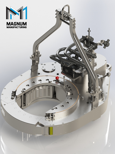
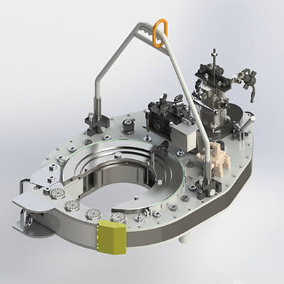
There is provided a power tong apparatus for use in well equipment. According to one embodiment, FIG. 1 illustrates a power tong assembly 100 having a main body 110 and a rotating body 120. FIG. 1 shows the rotating body 120 in a schematic view. One or more electric motors 19 provide torque through planetary gear box 18 to pinion 16. Pinion 16 can rest on bearings 14. Pinion 16 interacts with bull gear 2 to rotate rotating body 120. In this embodiment, bull gear 2 also accepts torque from hydraulic actuator 21 through hydraulic actuated clutch 20 and pinion 17, which may rest on bearing 15. In this embodiment, electric motors 19 are employed for low torque, high speed rotation of a tubular section in the power tong. Hydraulic actuators 21 are used for high torque, low speed rotation of the tubular. In an alternative embodiment, higher powered electric motors may be used to provide high torque capability to break the joint of well tubulars. Likewise, geared hydraulic actuators may be used to provide higher speed rotation of the tubular after the joint is broken.
Bull gear 2, according to the embodiment shown in FIG. 1, rests on bearing 13. Where multiple electric motors 19 and multiple hydraulic actuators 21 are employed, multiple pinions interact with bull gear 2 at different locations along the perimeter of bull gear 2. For example, FIG. 2 shows an embodiment having two electric motors 19 and two hydraulic actuators 21. Planetary gear boxes 18 and hydraulic actuated clutches 20 are then used to engage or disengage the respective electric motors 19 and hydraulic actuators 21 from bull gear 2.
Power tong 100, according to the embodiment depicted in FIG. 1, includes a number of hydraulic systems. Hydraulic power unit 28 supplies hydraulic power to hydraulic actuators 21 through directional control valve 26. For redundancy purposes, multiple actuators are contemplated, along with multiple redundant hydraulic power inputs. In FIG. 1, hydraulic power unit 28 also supplies hydraulic power to hydraulic actuated clutches 20 through directional control valve 25. One skilled in the art of hydraulics would understand that alternative designs are possible, for example, with multiple hydraulic power units, and different sorts of control valves.
One of the issues with power tongs employing rotating bodies is providing sufficient hydraulic power to grip the tubular. The transfer of hydraulic energy to the hydraulic system located within the rotating body, in the prior art, requires cumbersome rotary seals. Rotating body 120, according to the embodiment of the present disclosure shown in FIG. 1, has a self-contained hydraulic system that accepts mechanical energy imparted from the non-rotating portion of power tong 100. Upper mechanical link 6 resides above rotating body 120 and comprises two parts, an outer part 206 and an inner part 216. Outer part 206 of upper mechanical link 6 is fixed in place and attached to the fixed body through outside gripper cylinders 7. Inner part 216 of upper mechanical link 6 rotates along with rotating body 120. Upper mechanical link bearing 5 separates outer part 206 and inner part 216, allowing inner part 216 to rotate while still being mechanically attached to outer part 206. In alternative embodiments, multiple bearding rings may be used within upper mechanical link 6.
Outside gripper cylinders 7 reside in the fixed body 110 portion of power tong 100. According to the embodiment shown in FIG. 1, outside gripper cylinders 7 are powered by hydraulic power unit 28 through directional control valve 23. Directional control valves, known in the art, allow fluid flow into different paths from one or more sources. One skilled in the art would understand that many types of valves may be used to divert hydraulic power to the one or more cylinders contemplated in the present disclosure. Outside gripper cylinders 7 are attached to the outside part 206 of upper mechanical link 6. When hydraulic power is applied to outside gripper cylinders 7, the cylinders 7 retract, actuating the upper mechanical link 6 downward, towards rotating body 120. The hydraulic energy of outside gripper cylinders 7 is thus transferred into mechanical energy within upper mechanical link 6. Inner part 216 of upper mechanical link 6 is attached to gripper supply cylinders 4. According to the embodiment shown, gripper supply cylinders 4 reside within rotating body 120 and are attached to inner part 216 of upper mechanical link 6. As upper mechanical link 6 moves downward, mechanical energy is transferred back into hydraulic energy within gripper supply cylinders 4. FIG. 5 depicts a cross-sectional view of outside gripper cylinders 7 according to one embodiment of the present disclosure, showing outside gripper cylinders in the retracted position.
It is understood that many types of hydraulic cylinders may be used for the hydraulic systems of the present disclosure, such as a piston cylinder, plunger cylinder, differential cylinder, telescopic cylinder, and position-sensing cylinder. One skilled in the art would understand that alternative cylinder designs may be selected according to strength, cost, size, weight, force, ability to exert force in two directions, and other design parameters.
Within rotating body 120, grippers 27 make connection between rotating body 120 and the tubular, allowing power tong 100 to transfer torque to the tubular. In the embodiment shown in FIG. 1, gripper supply cylinders 4 supply hydraulic power to main gripper cylinders 3, which extend grippers 27 to make contact with the tubular. Hydraulic fluid is transferred from gripper supply cylinder through pilot-to-open (POC) valves 8 to main gripper cylinders 3. The POC valves 8 contemplated within the embodiment disclosed in FIG. 1 ensure that gripper 27 contact will not be interrupted in the event hydraulic power is lost at any point in the hydraulic systems other than the main gripper cylinders. This fail safe protects the tong from losing grip of the tubular while the power tong is under rotation. POC valves 8 include three ports, with the first and second ports connecting the gripper supply cylinders 4 and main gripper cylinders 3 across the valve portion of POC valves 8. The valve portion is a one-way valve, restricting flow from main gripper cylinders 3 to gripper supply cylinders 4 under normal conditions. POC valves 8 include a third port fluidly connected to the valve portion. When the third port is pressurized, the valve portion shifts, allowing fluid to flow back into gripper supply cylinders 4. Fail safe measures, such as POC valve 8 are contemplated to improve the quality of the disclosed embodiment, but one skilled in the art would understand that other designs are available, with other safety measures or even the lack of safety measures. The POC valves 8 contemplated in FIG. 1 represent one embodiment according to the present disclosure, though equivalent valves are known to those of skill in the art.
According to the embodiment in FIG. 1, hydraulic energy is applied from hydraulic power unit 28 to outside gripper cylinders 7, thereby retracting upper mechanical link 6 toward rotating body 120. Upper mechanical link 6 imparts mechanical energy into gripper supply cylinders 4, which transfer hydraulic energy to main gripper cylinders 3 to extend grippers 27 so that they make contact with the tubular. Power tong 100 may then apply torque to the tubular. FIG. 4 depicts a top view according to one embodiment of the present disclosure, where grippers 27 are in the extended position. FIG. 6 likewise depicts a cross-sectional view of FIG. 4 along the line indicated. FIG. 6 shows grippers 27 extended by main gripper cylinders 3.
To retract grippers 27, according to the embodiment shown in FIG. 1, a second mechanical link is used. Lower mechanical link 11 resides under rotating body 120. Like upper mechanical link 6, lower mechanical link 11 has a fixed outer part 111, and a rotating inner part 121. These two parts are separated by lower mechanical link bearing 10, which allows inner part 121 to freely rotate while still being mechanically attached to outer part 111. Fixed outer part 111 is attached to outside pilot supply cylinders 12. Outside pilot supply cylinders 12 are supplied hydraulic power through directional control valve 24 from hydraulic power unit 28. Hydraulic fluid flow into outside pilot supply cylinders 12 forces lower mechanical link 11 upward, toward rotating body 120. The upward movement of lower mechanical link 11 depresses POC valve cylinders 9, which in turn pressurize the third port of POC valves 8. POC valves 8, as contemplated in one embodiment, include three ports. With the third port unpressurized, POC valves 8 operate as a one-way valve, allowing hydraulic fluid to travel from gripper supply cylinders 4 to main gripper cylinders 3, but not the reverse. When the third port is pressurized, the one-way valve of POC valves 8 is converted into a two-way valve. According to one embodiment, main gripper cylinders 3 include a compression spring that is used to return gripper 27 to the open position. When POC valves 8 are pressurized and converted to a two-way valve, hydraulic fluid can flow back into the gripper supply cylinders 4. Compression springs in main gripper cylinders 3 push the hydraulic fluid back into gripper supply cylinders 4 and return grippers 27 to the open position.
At the same time the third port on POC valves 8 is pressurized to allow grippers 27 to relax into the open position, directional control valve 23 directs hydraulic power to reverse outside gripper cylinders 7. Upper mechanical link 6 thus moves upward, away from rotational body 120, thereby allowing hydraulic fluid to return from main gripper cylinders 3 through POC valves 8 to gripper supply cylinders 4. According to one embodiment, the negative pressure from gripper supply cylinders 4 pulls hydraulic fluid from main gripper cylinders 3, thus lessening or even removing the need for compression return springs within main gripper cylinders 9.
According to the embodiment shown in FIG. 1, outside pilot supply cylinders 12 contain compression return springs. When the operator removes hydraulic power via directional control valve 24, compression return springs retract outside pilot supply cylinders 12 and thus remove hydraulic fluid from cylinders 12, shifting lower mechanical link 11 downward, away from rotating body 120, and in turn depressurizing POC valves 8. The system is now reset and ready to accept energy to apply grippers 27 to a tubular.
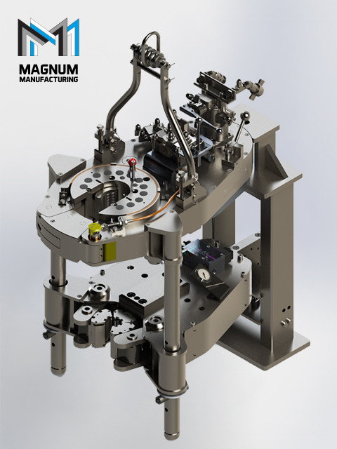
According to one embodiment depicted in FIG. 3, power tong 100 may be split in two, such as in an emergency situation. All of the main parts, including the main body 110, rotating body 120, bull gear 2, all bearings 5, 10, 13, both mechanical links 6, 11 may be split. Quick disconnects 29 are provided in the hydraulic fluid lines.
Although the embodiment disclosed in FIG. 1 has been described in detail, it should be understood that changes, substitutions, and alterations may be made without departing from the spirit and scope of the disclosure. For example, additional or fewer gripper assemblies are contemplated, with as few as one active gripper 27 in power tong 100. In addition, it is contemplated that, in an alternative embodiment, one mechanical link may provide mechanical energy to both extend and retract grippers 27 within rotating body 120.
Although the present disclosure and its advantages have been described in detail, it should be understood that various changes, substitutions and alterations can be made herein without departing from the spirit and scope of the disclosure as defined by the appended claims. Moreover, the scope of the present application is not intended to be limited to the particular embodiments of the process, machine, manufacture, composition of matter, means, methods and steps described in the specification. As one of ordinary skill in the art will readily appreciate from the present invention, disclosure, machines, manufacture, compositions of matter, means, methods, or steps, presently existing or later to be developed that perform substantially the same function or achieve substantially the same result as the corresponding embodiments described herein may be utilized according to the present disclosure. Accordingly, the appended claims are intended to include within their scope such processes, machines, manufacture, compositions of matter, means, methods, or steps.
The 14-100 hydraulic power tong provides 100,000 ft-lb (135,600 N∙m) of torque capacity for running and pulling 7- to 14-in. casing. The tong has a unique gated rotary, a free-floating backup, and a hydraulic door interlock.
Our 14-50 high-torque casing tong provides 50,000 ft-lb (67,790 N∙m) of torque capacity for running and pulling 6 5/8- to 14-in. casing. The tong has a unique gated rotary, a free floating backup, and a hydraulic door interlock.
The 16-25 hydraulic casing tong provides 25,000 ft-lb (33,900 N∙m) of torque capacity for running and pulling 6 5/8- to 16-in. casing. The tong features a unique gated rotary and as many as seven contact points that create a positive grip without damaging the casing.
Rigged up without rig modifications, our 21-300 riser tong is the only tong capable of producing 300,000 ft-lb (406,746 N∙m) of continuous rotational torque in both makeup and breakout mode. The power it achieves in a compact size compares with a conventional 24-in. casing tong.
The 24-50 high-torque casing tong provides 50,000 ft-lb (67,790 N∙m) of torque capacity for running and pulling 10 3/4- to 24-in. casing. The tong features a unique gated rotary, a free-floating backup, and a hydraulic doo


 8613371530291