
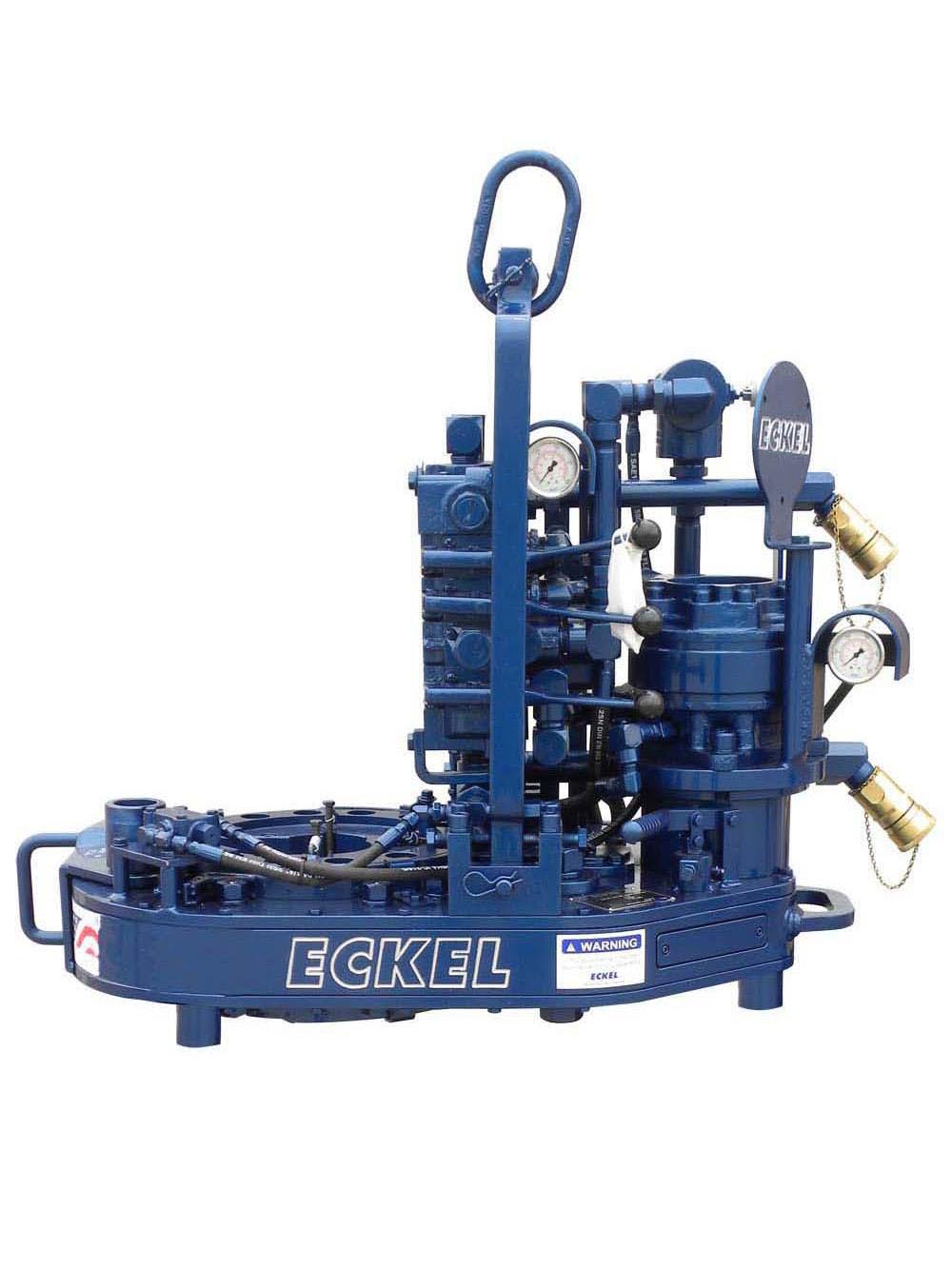
eckel power tong pricelist
A two-speed Hydra-Shift® motor coupled with a two-speed gear train provides (4) torque levels and (4) RPM speeds. Easily shift the hydraulic motor in low speed to high speed without stopping the tong or tublar rotation, saving rig time.
Used on corrosion resistant alloys (CRA) and fiberglass tubulars where reduced markings on the tubular is desired. Eckel"s Coated True Grit® Dies utilize Tungsten Carbide grit which provides many more points of contact on the surface of the tubular than our Pyramid Fine Tooth dies.
A patented door locking system (US Patent 6,279,426) for Eckel tongs that allows for latchless locking of the tong door. The tong door swings easily open and closed and locks when torque
is applied to the tong. When safety is important this locking mechanism combined with our safety door interlock provides unparalleled safety while speeding up the turn around time between connections. The Radial Door Lock is patented protected in the following countries: Canada, Germany, Norway, United Kingdom, and the United States.
The WD Tri-Grip® Backup is a high performance no compromise backup that is suitable for make-up and break-out of the most demanding connections. The WD Tri-Grip®Backup features a three head design that encompasses the tubular that applies an evenly distributed gripping force. The WD Tri-Grip®is a high performance backup with no compromises that is available for specific applications that provdies exceptional gripping capabilities with either Eckel True Grit® dies or Pyramid Fine Tooth dies.
The field proven Tri-Grip® Backup features a three head design that encompasses the tubular that applies an evenly distributed gripping force. The Tri-Grip®Backup provides exceptional gripping capabilities with either Eckel True Grit® dies or Pyramid Fine Tooth dies. The hydraulic backup is suspended at an adjustable level below the power tong by means of three hanger legs and allowing the backup to remain stationary while the power tong moves vertically to compensate for thread travel of the connection.
Eckel offers several models of torque control systems that are used to monitor the torque turn values when making up tubular connections (Tubing, Casing, & Drill Pipe). Any flaws in the make-up process will be readily shown in a graph.
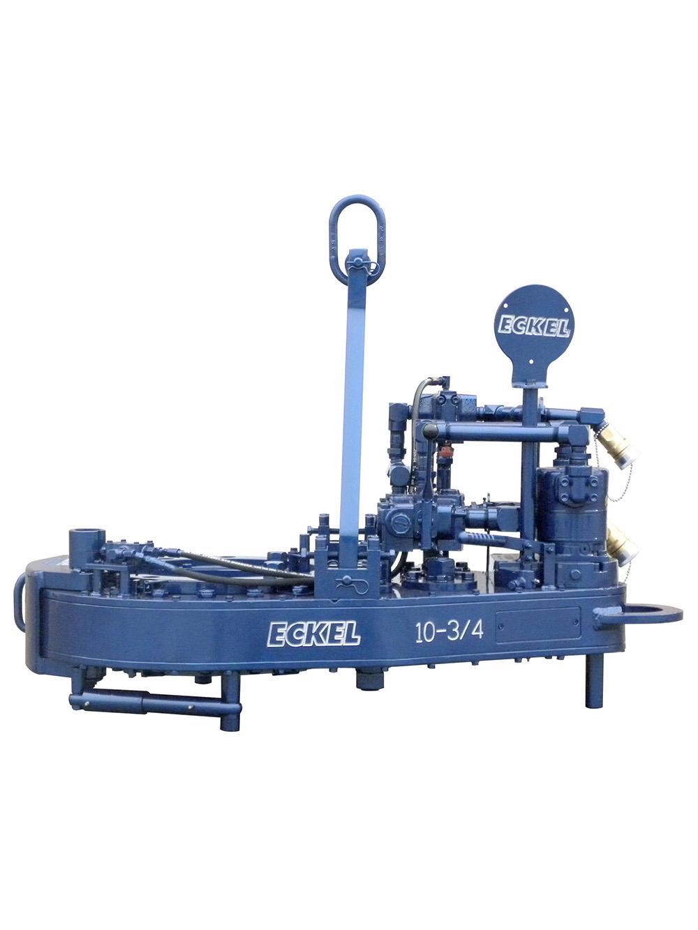
Casing Tongs provide make-up and break-out capabilities when running casing tubular in the drill hole to maintain well integrity. Casing tongs are available for various sizes from 5-1/2" to 36" and designed to handle high torque casing or lightweight casing. Available models: Standard, Hydra-Shift, High Torque, and Ultra High Torque with torques ranging from 15,000 ft-lbs up to 200,000 ft-lbs. Consistent operations between models reduce employee training.

1-1 FunctionalElementsofthe20-lnchTong ......1 t-z Hydraulic Drive System Schemat¡c D¡agram .... 2 1-3 ClutchandSpeedShiftDetails ..... 3 14 HeadB¡t¡ngAction.Makeup .......4 1-5 Head Cage Plate and Rotary Gear Deta¡ls ..... 4 1-6 BrakeBandsandsafetyDoor ,,....5 z-l TongDimensions .,.,... 7 ¿-¿ TorqueGaugelnstallation .....,.., I 2-3 Tonglnstallation .... 8 24 Hydraulicconnect¡ons .,... 9 3-1 OperatingControlsandGauges .,....11 4-1 TonglnspectionPo¡nts ..... "13 4-2 TongGreasePoints ,,,..... 14 4-3 TongAdlustmentPoints ...16 o-l Eckel Model 20 Casing Tong, Top Assembly (Exploded View) 21 o-z Clutch Assembly (Exploded Viewl 24 t"-J Pinion Assembly (Exploded View) 24 6-4 Pinion ldler Assembly (Exploded View) 25 6-5 Rotary ldler Assembly (Exploded Viewl . 26 6€ Tong Suspension Components, Simplified lllustration 27 6-7 Microswitch Assemblv 2A
1-1 SpecificationsEckel2O"CasingTong ........ 6 3-1 Operatingcontrolsandcauges ......11 4-1 RecommendedLubricants . .. r+ 5-1 TroubleshootingChart ....17 6-1 PartsList,EckelModel20CasingTong . ......20 o-¿ PartsList,CfutchAsembly ..,....23 6-3 PartsList,PinionAssembly ..,....23 6-4 Parts List, Pinion ldler Assembly . . . . 25 6-5 Parts List. Rotary ldler Assembly . , . . 26 6-6 TongSuspensionComponents ,,,.,. 27 o-t PartsList,MicroswitchAssembly ,,.,24 Copyright, 1979, by Eckel Mfg. Co. Inc. All Rights ReservedFirst Reprint 9/80 SECTION 1
This manual describes the function, operation The Model 20 Power Casing Tong, Figure 1-.1,and maintenance of the Eckel Model 20 Hydraulrc handles casing sizes as small as B-5/B inches and asPower Casing Tong. This section provides a func- large as 20 inches in diameter. The open-throattional description, system specif ications, and a de- design, combined with high-speed operation,scription of options and accessories available. Sec- assures both ease and speed in casing handling,tions 2 through 5 present the operatrng and main- A safety door on the open throat helps insuretenance aspects of the tong and Section 6 provides against accidents. The following paragraphs de-a fully illustrated parts list w¡th spare recommen- scribe the functions of the tong during casingdatrons. makeup or breakout operations.
Fígure l-1. Functíonal Elements of the 2?-lnch TongFUNCTIONAL DESCR IPTION nf the nncratinn nrcsst tre at fhe tono rv, tY if desired. I
Most users set this valve for maximum oressure so Operat ing f rom a hyd rau lic power un it, the that full pressure f rom the power unit is applied topower casing tong provides a maximum torque of the motor; however, you may set the valve for35,000 ft-lbs. The heart of the unit is a head-clos- lower pressures if desired. The maximum pressureing system which forces the heads together and ro- available, of course, depends upon the power un¡t.tates them by means of a cam-type rotary gear. Eckel Manufacturing Company recommends aThe rotary gear is driven by a two-speed gear train power unit that will deliver 3000 PSI pressure;powered from a piston-type hydraulic motor. however, a power unit capable of delivering 2500 PSI at 30 GPM or 1.000 PSI at 65 GPM is neces- In operation, the tong is suspended over the sary to maintain maximum speed and torque.drtll hole on a chain bridle. A snubbing line re-strains the tong from moving around the pipe as A hydraulic motor is mounted on the tong topfnrñr ro ic annliod plate through a motor adapter, and the other hy- draulic plumbing components are also mounted on HYDRAULIC DRIVE SYSTEM. Fisure 1-2 the tong top plate.is a hydraulic schematic of the drive system, Hy-draulic pressure from a separate power unit is GEAR TRAIN AND CLUTCH FUNCTION. Closure and rotation of the pipe-gripping heads are accomplished by means of a large rotary gear hav- r-rl4" couPLrNG REV ERSIBLE ing its inner diameter formed into a double cam MOTOR surface. The rotary gear rides on a double ring of Ylv¡ cam-follower rollers. A cutout on one side of the pR essu Re I rotary gear accepts the vertical pipe being worked. REL¡EF This topic explains how mechanical power is trans- VALVE mitted from the hvdraulic motor to turn the ro- PR ESSU R E tary gear in either direction.
I Gear Train Elements. The gear train, Figure I 1-3, comprises the clutch assembly, pinion assem- I bly, two pinion idlers, two rotary idlers and the .orlt,*o rotary gear. The selected high- or low-speed clutch gear engages the corresponding high- or low-speed pinion gear, and the pinion output gear drives the CONTROL VALVE two pinion idlers which drive the two rotary idlers. In driving the rotary gear, two rotary idler gears are necessary to bridge throat cutout gap. Figure l-2. Hydraulic Drive System Schematíc Diagram Clutch and Speed Shift. The clutch assembly (F igure 1 3) provides h igh- or low-speed opera-applied through screw-type hose connectors hav- tion, allowing faster operation when high torqueing built-in check valves. To prevent cross-connec- is not required. When higher torque is needed,tion of the hoses, the pressure hose from the power the low-speed gear permrts the operator to slowunit is designed to mate with a "l-inch connector the speed down and increase the torque,and the return hose mates with a 1-114 inch con-nector. Connection of the hoses opens the check The operator shifts the speed by raising orvalves to provide hydraulic pressure to the tong. lowering a shifting lever on top of the tong. As shown in the illustration, lifting the shift lever lifts The tong control lever acts as a throttle valve the shifting yoke, which lifts the shifting collar. Infor the unit. Pushing the lever applies pressure to this position, the shifting collar mechanicallydrive the motor in a forward direction (for make- couples the clutch shaft with the h igh-speed clutchup operation) and pulling the lever applies pressure gear. Lowering the shifting lever lowers the shiftingin a reverse d irection (for breakout). While the yoke which lowers the shifting collar, therebylever is in a neutral position, f luid circulates f reely mechanically coupling the clutch shaft with thethrough the valve and back to the return line. low-speed clutch gear. Then the selected clutch gear drives the corresponding pinion gear as pre- An adjustable relief valve permits adjustment viously described. An adjustable spring detent on
the shifting shaft holds the yoke and shifting lever During breakout operations, the backup pinin the selected position until the operator moves is placed in the breakout position so that the headsthe lever once again. bite in the reverse direction (see Backing the Heads for Breakout Operation). Then the operator pulls the tong control lever to cause the heads to bite HEAD OPERATIONS. The heads are enclosed and breakout the pipe. Finally, he pushes the leverwithin the rotary gear by the top and bottom cage forward to release the heads and back them off theplates. The heads are closed, rotated and opened pipe.by the combined actions of the rotary gear, brakebands and backing pin. As illustrated in Figure 1-4, the head-biting action is a function of the rotary gear inner surface Rotary Gear/Head Functions. During makeup cam design. When the rotary gear begins to rotate,operations, the pipe to be turned is first enclosed the heaC rollers roll uo onto the cam surface andin the tong, and the throat safety door is closed. force the heads inward from the oivot points untilThen, with the backing pin in the makeup position the heads bite the pipe. Further rotation then turns(as described later) the operator pushes the head the pipe to makeup (or breakout) the joint.control lever forward to cause the heads to biteand rotate the pipe. To release the heads and back Rotary Gear and Head Cage Rotation. Figureoff from the pipe, the operator pulls the tong con- 1-5 illustrates the cam follower rollers that permittrol lever outward. the semi-independent rotation of the cage plates bottom cage plate also rotates on a roller track identically with the top cage plate. This plate is bolted to the top cage plate to enclose the heads. The heads are pivoted from the top and bottom cage plates to bite or release as brought about by the cam action of the rotary gear on the head ro | | ers.
CAM FOLLOWER ROLLER (TORRINGTON } CAM FOLLOWER BOLT IECKEL)
CAM FOLLOWER NUT AND WASHER (EcKEL) BACK CAGE TOP TONG PLATE PLATE BOLT
BOTTOM CAGE PLATE BACKING LUG ROTARY IDLER BOTTOM TONG PLATE ROTARY qAM GEAR FOLLOWER ROLLER (EcKELl
Figure l-5. Head Cage Plate and Rotary Gear Details design permits ease of operation by permitting BACKING PIN entry of vertical pipe that projects above the level ROTARY of the tong. For safety purposes it is necessary that GEAR the throat opening be closed during operation to . CAM prevent personnel injuries or damage to the equip- SURFACE ment. A double safety door (Figure 1-6) serves both to close off the front during operation and to HEAD provide an extra margin of support for the housing ROLLER du ring h igh-torque operation.
BRAKE SPECIFICATIONS BAND ADJUSTM ENT < The specif ications for an operating tong must BRAKE \THROAT consider the hydraulic power unit as well as the BAN D SAFETY tong itself. ADJUSTM ENT DOORS
HYDRAULIC POWER UN¡T SPECIFICA- TIONS. The power tong is designed to be powered Figure l-6. Brake Bands and Safety Door by a hydraulic power unit capable of delivering at least 2,500 pounds per square inch (PSl).are held stat¡onary as the head rollers roll up ontothe cam surfaces to force the heads in against the At least 65 gallons of hydraulic oil, depend-pipe. As the heads bite the pipe, the friction of the ing upon the power unit used, are recommended tobrake bands is overcome. Then the cage plates be- ñnar2ta thé r" ¡v fr\nñ rv,,y.gin to rotate with the rotary gear, thus turning thepipe that is now gripped f irmly by the heads. TONG SPECIFICATIONS. Table 1-1 lists the 20" Casing Tong. specif ications for the Eckel Backing the Heads for Breakout Operation.The backing pin shown in Figure 1-5 permits the OPTIONS AND ACCESSO R I ESheads to bite in the forward direction for makeuoand in the reverse direction for breakout. Options for the 20" casing tong include lift- cylinder with lift cylinder control, spring hanger, When the pin is placed in the left-hand hole, and torque meter, These optional items are de-forward operat¡on causes the heads to bite and scribed in the following paragraphs.rotate to make up the joint. However, reverseoperat¡on causes the backing lug to strike the back- LIFT CYL¡NDER AND CONTROLS. A Iifting pin and force the cage plates around with the cylinder as illustrated in Figure 2-3 is opt¡onallyrotary gear. Thus, in the reverse direction, the head supplied with the 20" tong. In operation, thisrollers cannot cam up on the rotarv cam and the cylinder provides a means for raising and loweringheads do not bite. the tong during operations.
lf the pin is placed in the right-hand hole, the Lift Cylinder Control. When a lift cylinder isopposite action occurs and reverse operation causes ordered with a tong the tong contains an additionalthe heads to b¡te, while forward operation causes control lever for controlling the left cylinder up orthe backing lug to stroke the backing pin and force down. The control lever-operated valve is identicalthe head cage around with the rotary gear, thus to the tong operating control lever. This lever isinhibiting the heads from biting in the forward illustrated in Figure 2-3 and its operation is shownd irect io n . in Figure 3-2 and Table 3-1. Pulling the valve out- ward provides hydraulic pressure from the hy- In summary then: for makeup, the pin is draulic power unit to operate the lift cylinderplaced in the left-hand hole and the heads bite in upward, and thus to raise the tong while pushingforward direction; and for breakout, the pin is the control lever forward operates the cylinderplaced in the right-hand hole and the heads bite in downward to lower the tong. The center lever po-the reverse direction. sition is the neutral position that does not operate the tonq in either direction. Open Throat and Safety Door. The open throat Table l-1. Specifications Eckel 20" Casing Tong
RPM: Pipe Space Required 9.250 lnches (234.95 mm.) H igh 53 at 65 G.P.M. (250 L/min.) Max. Elevator Diameter (Unlimited-Tong comes off Pipe) Low 8 at 65 G.P.M. (250 L/min.) Pipe C.L. to Anchor C.L. . . . 52 Inches (1320.8 mm,) Hydraulic Requirements: * Weightr High Speed 65 G.P.M. at 1.000 P.S. r. Approximately 2,600 Pounds (250 L/min. at 70.3 (1179.35 Ks.) Ks./cm2) Heads Available: Low Speed 30 G.P.M. at 2,500 P.S. r. For Casing Size 8-518,9-518, 10-314 (125 L/min. at 11-3/4,13-3/8,16" 175.5 Kg.lcm2l 18-5/8.20" O.D.
L¡ft Cyl¡nder. While the lift cyl¡nder may be TOROUE GAUGE ASSEMBLY. The optionalconnected directly to the tong bridle, it is sug- torque gauge assembly (Figure Z-21 is used to mea-gested that the optional spring mount be inserted sure the torque exerted while the tong is used inbetween the lift cylinder and the bridle to permit makeup or breakout operations. Consisting of atong movement during makeup or breakout opera- hydraulic cylinder and torque meter connectedtions without exertinq undue stress on the bridle together by a pressure hose, the torque gaugeand the lift cylinder. assembly senses and indicates the torque developed during an operation. For operat¡on, the hydraullc SPRING HANGER. The optional spring hanger cylinder is connected by a shackle to the rear of(Figure 2-3) is designed to permit the tong to move the tong; and a snubber line is connected to theup or down to allow for thread length in makeup cylinder. The snubber line is tied off to a solid partand breakout operations. When used, the spring of the rig structure to form an angle of 90" in orderhanger should be attached directly to the tong to yield accurate torque readings.bridle ring and used as a hanger for the tong. SECTION 2
Installation of the power tong requires con- A. TONG LENGTH & HEIGHTsideration of the tong itself, the hydraulic powerunit to be used, and the accessories that will be re-quired. 24.8 | 2 rN TONG CONSIDERATIONS. The 20" casins 630.225 MMtong is capable of handling pipe sizes from B-5/B tf I
inches to 20 inches in outside diameter. The headsto be used with the tongs, of course, depend uponthe size pipe being used. Refer to Table 1-1, Speci-fications for the various heads provided with the 76.00 rNtong. r 930.4 MM
Head lnstallation. Reolace the heads that areon the tong with the correct size heads according B. TONG WIDTH & THROAT WIDTHto the followlng procedure.
43.250 rN 20.50 tN Do not attempt to change heads r098.6 MM 520.7 MM with power unit in operation. Fail- ure to observe proper pre-cautions could very easily result in loss of an arm.
2. Swing in and lift out the heads. Figure 2-1. Tong Dimensions 3. Select proper heads for pipe to be worked and install in head cage in reverse order of ACCESSORY CONSIDERATIONS. Tons in- steos 1 and 2. stallation requires that the necessary accessories be available for the type of operatlon to be per- Tong Space Requirements. You should con- formed.sider the space requirements of the tong, both instorage and in operation. Figure 2-1 gives the tong Installat¡on of Torque Gauge Assembly. Mea-dimensions. surement of the applied torque requires a torque gauge assembly installed on the equipment, Once POWER CONSIDERATIONS. Before installing installed, the torque gauge assembly becomes anthe tong for f ield operations, you must be sure that integral part of the unit. To install the torquean appropriate power unit is available and that the gauge on the tong, proceed as follows.power unit is adjusted for use with the tong. Tooperate the tong within its full capability, the re- 1. Using three mounting screws, mountlief valve on the hydraulic power unit should be torque gauge into position on torque-adjusted to 2500 pounds per square inch and the gauge plate, Figure 2-2.bypass valve should be adjusted to 900 - 1000 PSl. Refer to the power unit manual for the procedure 2. Route hose to avoid interference with tonqon power unit valve adjustments. operat io n. 3. Adjust turnbuckles to level tong as nec- essarY to ensure an even bite on the caslng"
Lift Cylinder Considerations. lf the system isnot counter oatanced, a lift cylinder should beused. Also, if an Eckel lift cylinder is to be used,the tong must be equipped for operating with a liftcylindei. For lift cylinder operat¡on, the tong mustháve an additional valve section" The lift cylindershould be suspended from the line that will hangthe tong as shown in Figure 2-3.
HANGING THE TONG" The tong rs trans-ported to the well site and hung into position asillustrated in Figure 2-3 and as follows: TONG
cat line on drilling rig or an. es- Figure 2-3. Tong lnstallation 2. Using the pecia"lly rigged line, lift tong to desired height in wórk area and secure" Be sure lift 4 Connect snub line to hydraulic cyllnder to cylinder or counter-balance system ts pro- restrain tong rotation and to provide torque perly in Place and functioning. read ings for oPerations. 5. Secure other end of snub line to a solid CI\UTION part of rig to form a 9O-degree angle with tong center line To be sure connectors are com- pletely tight, first tighten them un- CONNECTING THE HYDRAULIC LINES. til travelis restricted and the end ofThe hydraulic couplings, Figure 2-4, contain check the thread travel appears to bevalves to prevent loss of hydraulic f Iuid when the reached. Then try to tighten thelines are disconnected. The check valves are closed valve further to be sure first restric-until the hydraulic hoses are connected. Proper tion was not a false tightness. Thentightening of the hydraulic hose connectors opens continue to t¡ghten the f¡tting untilthese check valves. However pressure may be in the connection is tight.tong when the lines are disconnected so that thevalves resist opening. In such case, the connectors ? lf a lift cylinder is used, hook up the hosemay seem to reach the end of thread travel when, from lift cylinder to connector provided onin reality, the check valve operation is restricting tong.further tightening. When making up these connec-tions you should be sure that you have tightened 4. Start power unit and allow hydraulic f luidthe valves tight and have not simply reached a to circulate through tong untilfluid reaches"false" tightening due to the resistance of the operati ng temperature.check valves. NOTE
This period will vary according to CONNECT HYDRAUI.¡C the ambient temperature, In severe PRESSURE LINE FROM POWER UNIT weather conditions, you may need to operate system for several min- CONNECT HYDRAULIC utes before using tong, On the RETURN LINE FROM other hand. in warm climates a POWER UNIT very brief warmup period will be adeouate.
Connect the hoses as follows: WARN ING 1. Hook up pressure hose to one-inch fitting on tong by forcing connectors together while turning f itting. When replacing hydraulic hoses, piping and fittings, be sure replace- a z- Hook up return hose from power unit to ment components are rated at no 1 114 inch connector on tong, as for one- less than 3,000 PSI working pres- inch f itting above. sure and 10,000 PSI burst pressure. SECTION 3
GENERAL OPERATION OBSERVING TH E OPERATING FUNCTIONS. Before starting a new job and each day before the Before operating the unit, you should become work begins, perform the following operations andthoroughly familiar w¡th the operating controls be sure the tong responds correctly.and gauges; then, before initial operation and dailythereafter you should perform the recommended 1. Place backing pin in left-hand hole.adjustments and operational checks. 2. Move shifting lever to high-speed positionOPERATING CONTROLS AND INDICATORS ("P)" Figure 3-1 illustrates the operating controls and 3. Push tong control lever forward and verifygauges. For the functions of the controls and that heads bite and head cage turns at highgauges refer to Table 3-1. soeed.
PRE-OPERAT]NG CHECKS 4. Pull tong control lever back to neutral and move the shifting lever to the low speed po- After installation, you should check out the sition (down).system to be sure that any necessary adjustmentsare made and that the system is functioning cor- 5. Again push tong control lever and verifyrectly. Belore attempt¡ng operation, verify that the heads bite and head caqe turns at the lowfollowing initial adjustments have been made. speeo.
PRECAUTIONS TO OBSERVE. The following 6. Return control lever to neutral position.precautions shou ld be observed to ensure saf eo Oeratro n. l. Use tong control lever to operate tong so that head plate and rotary gear openings 1. Be sure that operating personnel are are aligned with throat in housing. checked out on proper operation of tong, and be sure that they are aware of safety B. Place backing pin in right-hand hole. Re- req u irements. peat steps 2 through 6 to check breakout operation. 2. Be sure that all lines and eouioment associ- ated with hanging and securing tong are of NOTE adequate size and in good conditron, lf the heads fail to bite, the brake POWER UNIT OUTPUT PRESSURE. Deter- bands probably need ad justment.mine that the power unit output pressure has been Adjust the bands as described in theproperly adjusted. lf you do not know, refer to the topic on Initial Adjustments in theinstruction manual on the power unit and perform Maintenance Section.the output pressure adjustment procedure for therequired pressure. 9. lf lift cylinder option is installed, pull lift cylinder control lever back and verify that TONG PRESSURE RELIEF VALVE. lf a re- cylinder operates to l¡ft tong.lief pressure is to be set on the tong, verify that thesett¡ng has been made previously; or if you do not 10. Push lift cvlinder control forward and ver-know, refer to the maintenance sectton for the ify that cylinder operates to lower tong.proper procedures. TYPICAL OPERATING SEOUENCE BRAKE BANDS. Determine if the brake bandshave been adjusted properly. lf necessary perform Typical operation of the tong is described inthe pre-operational check to make this determina- the following procedures.tion. Refer to the Maintenance Section for adiust-ment of the brake bands. lNlTlAL OPERATIONS. After the tonq is
Control or Gauge FunctionBacking Pin ln Makeup Hole Allows tong to bite when operated clockwise for makeup. In Breakout Hole Allows tong to bite when operated counterclockwise for breakout.Shifting Lever Up Position Shifts tong gear train into high-speed position. Center Posit ion Neutral position - motorand clutch shaft turn but rotary gear does not rotate. Down Position Shifts tong gear train to low speed.Tong Control Lever Forward Position Operates rotary gear and cage plates clockwise. For makeup, head bites and for breakout head releases. Makeup or breakout function depends upon position of backing pin. Back Position Operates rotary gear and cage plates counterclockwise. For breakout, head bites and for makeup head releases. Makeup or breakout func- tion depends upon position of backing pin.Torque Gauge Registers torque applied to casing being worked.Lift Control Lever When present, located to right of Head Control Lever.(optional - not shown) Forward Position Operates lift cylinder to lower tong. Back Position Operates lift cylinder to raise tong.
TONG CONTROL LEVER TOROUE GAUGE BACKING MAKEUP
11transported to job site, hoisted into operating po- 1. lnitially select high-speed operation bysition, snubbed, leveled, and connected with power moving shifting lever up.unit as described in Installation Section, proceed asfollows. 2. Operate tong control lever as follows:
1. Be sure shifting lever and control lever(s) a. To begin turningcasing clockwise for are in neutral position. makeup operation, push control for- ward. 2. Start hydraulic power unit. b. To begin turning casing counter clock- 3. Perform a pre-operational check and make wise for breakout operation, pull control any required adlustments before operation. lever back.
4. Place backing pin in makeup hole for make- 3. Once tong stalls out, release tong control up operation or in breakout hole for break- lever and move shifting lever to low-speed out operation. (See Figure 3-1). position.
POSITIONING TONG AND ENCLOSING 4. Operate tong control lever to complete tor-CASING. After performing the initial operations, queing operation.position the tong for the makeup or breakout workto be done. 5. Observe reading on torque gauge and when proper torque is obtained, move tong con- "1. Position the tong as proper height for grip- trol lever in opposite direction to back off ping casing as follows: head.
a. lf tong is installed using a counter-bal- 6. Reposition casing as necessary, and repeat ance system, lift or lower tong to desired above steps as required for each joint. position. FORWARD.REVERSE ALTERNATION. If it b. lf a lift cylinder is used, operate the lift is desired to quickly operate the tong forward and cylinder control lever (right-hand han- backward (as in the case of cross-threaded pipe dle) on the tong to position tong. joints) proceed as follows:
2. Place tong on castng section positioned for maKeup or oreaKout. CAUTION
3. Close throat safety door, then perform In th is method of oPeration, be operation as described in next topic. sure the tong is always able to griP the pipe. Operation of an empty 4. After operation, remove tong from casing, tong wlth the backing Pin in neu- open front safety door and push tong back tral (i.e. removed) would allow the off casing, then re-close door. backing lug to rotate until striking +L^ ^^^^ ^r^+^ Lr ru udgv ^^.tcers each revolu_ Prdr-u Jpc OPERATING THE TONG. To operate the tion. Such operat¡on could damagetong, proceed as follows: the tong.
Be sure no part of the body or - Operate tong forward, then quickly reverse clothing is in tong head area and be d irect io ns. sure no cables or equioment other than casinq are enclosed in throat. 3. Repeat step 2 as requlred to loosen joint.
Servicing the tong consists of inspection, lubri- INSPECT HEAD ROLLERS. lnsoect headcation, tests and adjustments. Should servicing re- rollers to be sure they turn freelV. Lubricate asveal requirements for repairs, refer to the appro- outlined under Head Roller Lubrication procedure.priate 0ortions of Sections 5 and 6. MONTHLY MAINTENANCEDAILY INSPECTION Once each month make following checks and Figure 4-1 illustrates the points that should be take appropriate corrective action.inspected at the start of every job and once everydav thereafter. 1. Check cam follower rollers for wear or breakage, and replace if necessary.
Proper lubrication is important to the opera- tion and long life of the tong. This topic describes both the lubricating grease and the hydraulic fluid requirements for the tong.
HYDRAULIC FLUID. Under normal ooeration the tong should remain charged with hydraulic f luid even when the hydraulic hoses are disconnec- ted. This is because check valves at the disconnect BRAKE BANDS points retain the hydraulic fluid within the tong when the connection is separated. However, should CLUTCH hydraulic f luid be Iost f rom the tong due to leaks or during maintenance, you should recharge the tong by connecting the hoses from the hydraulic power unit and adding f luid according to the in- Fígure 4-1. Tong lnspection Points structions in the power unit manual.
OVERALL INSPECTION. Inspect the unit and GREASE ZERTS. At the beginning of each jobits accessories for obvious damage, evidence of hy- and daily thereafter, you should use a grease gun todraulic leaks, etc. Refer to the overhaul procedures grease the various grease zerts. In general, youfor removal and replacement of any faulty parts. should be liberal with grease. Over-greasing will do no harm, while under greasing can result in exces- BRAKE BAND INSPECTION. Inspect the sive wear. Figure 4-2 shows the Iubrication pointsbrake bands to be sure that each band is intact and and Table 4-"1 gives information on the type ofnot excessively worn. lf a brake band begins to grease to be used.wear into the rivets, the band should be replaced. In the steps below the item numbers enclosed CHECK HEAD DIES. Inspect head dies to be in parenthesis refer to grease points identified insure that biting edge is not worn excessively and is Figure 4-2,capable of biting effectively. Change the dies if re-qu ired. 1. On top of tong, grease shifting shafi (7). TIGHTEN BOLTS. Tighten two head pivot 2. Grease four idler bearings (5), (6), (B),bolts and three head caqe bolts. and (9).
You must rotate cam and cage plates as necessary to obtain access to bearings. 4. Beneath tong, grease clutch assembly (12).
After applying power to turn rotary gear, disable hydraulic sYstem be- fore proceeding.
CAM FOLLOWERS. When greasing cam fol- Figure 4-2. Tong Grease Points lower zerts, lubricate outside of cam follower rollers as listed below:
1. Use gear grease as described in Table 4-1. WARN I NG 2. Apply grease liberally to outside of each roller. After applying power to turn rotary gcdr ^X^. ¡-^a ^^¡ ru udgú dr Prd LUJ, disable hy- nl¡t^a HEAD ROLLERS. Lubricate head rollers as draulic system before proceed I ng. f ollows:
2. Apply gear grease liberally to outside of After applying power to operate head ro llers. gears, disable hydraulic system be- fnro nrncoo¡l inn GEAR GREASE. To pack the tong with greaserefer to Figure 4-2 and Table 4-1, and proceed as c, Operate tong to distribute grease thenfollows: disable hydraulic power and repeat steps a and b.
TESTS AND ADJUSTMENTS Packing the gears while the power unit is operating is extremely dan- The following tests should be made and the ad- gerous. Failure to observe proper justments performed as indicated. precaution in maintaining this unit could very easily result in loss of BRAKE BANDS. At the beginning of a job and an arm, at the start ofeach shift thereafter, perform the brake band test and brake band adiustment as re- 1. With power unit connected and operating, quired. rotate rotary gear so that opening is turned to back of tong. Brake Band Test. Check each brake band ad- justment according to the following steps: 2. Disable tong by both of the following methods. 1. Place backing pin in Makeup position.
2. Operate the tong several times and verify WARN I NG that the heads bite at each operation, 3. Place backing pin in Breakout position. Keeo hands out of the head area while the power unit is operating. 4. Operate tong several times and verify that heads bite at each operation. a. Disconnect power from power unit elec- trical motor or turn off diesel engine as 5. lf heads fail to bite in either Makeup or applicable, shift speed lever to neutral, Breakout position of backing pin. adjust and set control lever to neutral. brake bands.
b. Disconnect hydraulic pressure line (1- Brake Band Adjustment. When inspection or inch line) from tong at hose connector. test indicates the requirement, adjust the brake bands according to the steps given below. Refer to 3. Remove cover from clutch inspection port. Figure 4-3 f or the adjustment points.
5. lf additional adjustment is indicated, re- REL¡EF peat steps 1 through 3 until proper opera- VALVE tion is achieved. SHIFTING GAUGE DETENT TOROUE CHECK AND ADJUSTMENT. The PORT reliel nressr rrc fnr thtr tñnn mar¡ hp qof tO achieve the maximum torque desired. The following pro- cedures describe the method for checking and ad- Figure 4-3. Tong Adiustment Points. justing the relief pressure to obtain the torque desired (up to the maximum torque of the tong). NOTE NOTE A total of one-half to one turn should normally be sufficient. Refer to the manual on the power unit and be sure unit is adjusted to SHIFTING DETENT. The shifting detent that provide the required operating pres-holds the shifting mechanism in the selected speed SU TC.is ad justable. This adjustment should be checked atthe beginning of a job and at the start of each shift Maximum Torque Adjustment. Adjust thethereafter, and the detent should be adjusted if maximum torque to the desired value according torequired. the following steps.
Detent Operational Check. Check the opera- 1. Set up tong on a casing or tong test standtion of the shifting detent as follows: with casing coupled or installed so that it cannol turn. 1. Raise shifting handle to High Speed posi- tion and verify that the control snaps into 2. Be sure that torque gauge is correctly in- position. stalled and in proper operat¡on.
This section contains instructions for trouble- REPAIRshooting, repair and overhaul of the tong. Afterany major repair or overhaul, the tong should be In general, repair consists of replacing worn orserviced as outlined in Section 4. broken parts. When a part is determined to be faul- ty, either through inspection or through an opera-TROUBLESHOOTING tional check, you should remove the part and re- place it with a new part according to the proce- Tong troubleshooting consists of locating ob- dures and instructions in the following topics. Theserved symptoms on the Troubleshooting Chart, component parts are illustrated and identified inTable 5-1, determining the probable cause, and Section 6.correcting the problem as suggested.
TONG FAILSTO GRIP Wrong size heads in tong or lnstall correct head and roller assemblies. wrong rollers in tong heads
Heads come out of neutral cam Undersize pipe f nstall oversize rollers 11/16" OD larger). but will not penetrate p¡pe. Tong not hanging perpendicular Adjust hanging bridle turnbuckles until to pipe tong hangs level.
Heads do not come out of Brake bands not tight enough Tighten brake band adjustment nuts 1/4" neutral cam turn intervals until tong grips.
TONG DOES NOT RELEASE Brake bands not tight enough Tighten brake band adjustment nuts 1/4" (BACK BITES} turn intervals until tong grips.
TONG DOES NOT DEVELOP Power unit pressure not set Refer to instruction manual on power unit. SUFFICIENT TOROUE high enough
Power unit properly set, but With pressure gauge in the relief valve relief valve on tong not set "gauge port," stall tong and turn valve high enough relief screw adjustment clockwise until pressure is set correctly.
MOTOR RUNSBUTTONG Faulty clutch or shifting Check clutch and shifting mechanism and DOES NOT ROTATE mechanism repair as necessary.
TONG HANGS UP UNDER Excessively worn or broken cam Replace cam follower, dumbbell, or idler LIGHT LOAD follower, dumbbell, or idler beari ng. bearing
Overhaul consists of disassembling the tong, REASSEMBLY. Reassembly of a componentexamining each part, replacing any worn or dam- or of the entire tong consists of replacing the partsaged parts and then reassembling the tong. All in the reverse order of disassembly, then perform-damaged or worn parts are to be replaced with ing the service outlined in Section 4. However,identical parts as identif ied in Section 6. certain procedures for performing reassembly after service or during replacement of certain wear parts DISASSEMBLY. During overhaul, the tong are presented in the following topic.should be completely disassembled. For replace-ment of a faulty part, components need be re- PARTS REPLACEMENT. In general, partsmoved only as required to obta¡n access to, and re- replacement consists ofdisassembly as necessarymove, the faulty part. In general, disassembly re- to obtain access to the part to be replaced. How-qu¡rements become obvious from the f igures in the ever, replacement of certain parts as required forillustrated parts list; however, procedures for per- service and as indicated by the functional tests,forming disassembly necessary for service as well is described in this tooic.as replacement of certain wear parts are presented
1B Brake Bands Replacement. Should the brake To remove and replace these plates, proceedbands become broken or excessively worn, they are according to the following steps. The numbers into be replaced in accordance with the following parenthesis refer to item numbers in Figure 6-1.procedure. Numbers in parenthesis refer to itemnumbers in Figure 6-1. WARNING 1. Remove adjusting nuts (18) and bolts (17) from top brake band (16). Keep hands out of the head cage 2. Remove brake band (16). Refer to parts while the power unit is operating. list, item 16, for part No. of new band. 1. Remove heads as described in Section 2. 3. Grease new brake band before replacement. 2. Loosen brake bands as necessary to free two cage plates (23). 4. Place new brake band around cage plate rnr"l ronleno trn,¡ [611s (17) and adjusting 3. Remove back cage plate bolt (9), and re- nuts (18) through brake band lugs (19). move two side cage plate bolts (14).
6. Underneith tong, remove brake band re- 5. Remove bottom cage plate (23), taking tainer nu| 1221,lockwasher (21) and brake to damage three cage plate spacers care not band retainer Q0\ for bottom brake band. (15).
This section contains a complete illustrated illustrate the subassemblies not broken down in thenertc lict fnr tho tr"kel Model 20 Tong. Figure 6-1 top assembly illustration, and Table 6-2 throughYvr !v "
101539 Tong Plaie eolti3TB in NC X 1 -114 in. Hex Head 1B 4 103484 Bottom Tong Plate 1
5 10161 4 Tong Plate Bolts 5/B in N C X 1 -1 14 in. F lat Head Socket 4 6 100423 Top Cage Plate 1
24 1 00549 Eckel Cam Follower Pin 48 )q 100429 Eckel Cam Follower Roller 48 26 101183 Eckel Cam Follower Grease ZerI 114 in.28 Thread 48 27 101191 Torrington Cam Follower CRS-32 14 "10"l 28 1 86 Cam Follower Grease ZerI - Drive Grease Zert 1L 29 100428 Eckel Cam Follower Brass Bushing 20 JU 1 00430 Eckel Cam Follower Spacer 20 31 101721 Cam Follower Washer 7 /B in. Lock Washer 62 32 101765 Cam Follower Nut 7lB in. NF Jam Nut 62 1 00952 Head Roller (2 per set) 2 34 100398 Head Roller Pin (2 per set) 2 35 200-cT-1007 Rotary ldler Assembly (See Figure 6-2for Breakdown) 2 36 200-cT-1006 Pinion ldler Assembly (See Figure 6-3 for Breakdown) 2 37 200-cT-1005 Pinion Assembly (See Figure 6-4 for Breakdown) 1
ll Table 6-1. Parts List, Eckel Model 20 Casing Tong - Figure 6-l (Cont.) I NDEX PART NO, DESCR IPTION OUANTITY
40 10041 1 Backing Lug 41 101655 Backing Lug Screw 112in. NC X 1 in. Socket Head 42 1 00540 Tong Door 43 1 0051 5 Door Shaft 44 101764 Door Shaft Nuts 7/8 in. NF Thin Lock Nuts 45 1 00543 Door Bearing Washer 46 100542 Door Bearing Spacer 47 101809 Door BearinS 1299R14 48 102482 Door Ear Bearing Housing 49 10041 1 Shifting Yoke 50 100481 Shifting Yoke Bushing 51 101105 Shifting Yoke Retainer Ring TRUARC 5100-100 52 100474 Sh ifting Shaf t 53 1 00480 Botto


 8613371530291