
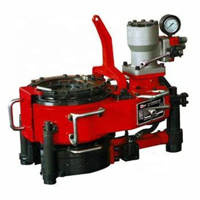
foster power tong parts free sample

ETI Ref: 0205431 ea Drag Ring 9-7/8"" OD - 6"" ID Parts No: 38747ETI Ref: 0205441 ea Drag Ring 9-7/8"" OD - 6"" ID Parts No: 38747ETI Ref: 0205451 ea Drag Ring 9-7/8"" OD - 6"" ID Parts No: 38747ETI Ref: 0205461 ea Drag Ring 9-7/8"" OD - 6"" ID Parts No: 38747ETI Ref: 0205471 ea Drag Ring 9-7/8"" OD - 5"" ID Parts No: 58-160-2ETI Ref: 0205481 ea Ring Gear 9-7/8"" OD - 6"" ID 10062336/0033261ETI Ref: 0205491 ea Drag Ring 9-7/8"" OD - 6"" ID 10063585ETI Ref: 0205501 ea Drag Ring Sleeve 11-1/8"" OD - 8-1/8"" ID Parts No: 93-285-1
14/16ETI Ref: 0205511 ea Drag Ring 10"" OD - 6-1/4"" ID Pn: 58-160-2 / sn: 39283ETI Ref: 0205521 ea Bottom Cap 17"" OD - 8-1/8"" ID Parts No: 93-286-1ETI Ref: 0205531 ea Drag Ring Cover Plate 10-1/4"" OD - 4-7/8"" ID Parts No: 93-161ETI Ref: 0205541 ea Drag Ring Cover Plate 10-1/4"" OD - 6"" ID Parts No: 93-161-11ETI Ref: 0205551 ea Drag Ring Cover Plate 10-1/4"" OD - 6"" ID Parts No: 93-161-11ETI Ref: 0205561 ea Drag Ring Cover Plate 10-1/4"" OD - 6"" ID Parts No: 93-161-11ETI Ref: 0205571 ea Drag Ring Cover Plate 10-1/4"" OD - 6"" ID Parts No: 93-161-7ETI Ref: 0205581 ea Drag Ring Cover Plate 10-1/4"" OD - 6-1/8"" ID N/AETI Ref: 0205591 ea Drag Ring Cover Plate 10-1/4"" OD - 6"" ID N/A

Oil Level Lube FittingsOPERATIONAL MAINTENANCENote 1. Note 2. Note 3. Note 4. Lube fittings should be greased weekly. Transmission should be checked after every trip, and if water or dirt is found in transmission, change oil. Under normal conditions oil should be changed every 100 work hours. Clean and grease Tong Head and Backup Tool after every trip, use kerosene or solvent and a wire brush for cleaning. After cleaning, apply cup grease to jaws, pins, ring gear and top seal. Hazards of steam cleaning Tong Head are: Water will be forced by top seal into transmission. also removing all lubricants from top seal and causing it to harden. If steam cleaning is used, Guide Bell should be bolted on place and after cleaning, the transmission should be checked for the presence of water.
SAFETY POINTS AND WARNINGSNote 5. Note 6. Note 7. Note 8. CAUTION, keep hands clear of Tong Head while Tongs are in operation. Caution should be taken while operating this equipment, as parts inside the Tong Head rotate. Do not crawl or stand under Tongs as hydraulic line could be cut or broken and Tongs will fall. Do not operate Power Tongs until the Anchor Arm is attached to the Tong and Anchor Post. Power should be off before any size equipment change, maintenance, or any other work is done to this equipment.DATESubsidiary of Galveston-Houston Company
They can also be made from synthetic fiberslass, aluminum, plastic, silicone, and polyurethane.Phase power tongs are designed to lighten and pressure from the base of the vehicle.
They are simple and lightweight, easy to transporting. On the other hand, power tongs have different functionality. In technology, locking fosters have friendship as well as a kind of power tongs.
Electric power tongs are great for those who need to check the condition of their equipment. Explore Alibaba.com to find more electric power tongs for sale, such as gold power tongs, mining power tongs for sale, and electric power tongs for all purpose. Find mining equipment suppliers on Alibaba.com to provide your customers with electric power tongs for all mining purposes.
Mining people are more sensitive to the tools they to. There is also a need for fostering recovery of mining mins, and in some cases, the as common as these power tongs for mining are other tools. It"s common for some miningers to have a fostering recovery on mining, and in the case of mining gold.

The present invention generally concerns tooling and equipment used in the maintenance and servicing of oil and gas production wells, and more particularly relates to a back-up tong of the type used in conjunction with a power tong to make or break threaded joints between successive tubing elements which make up the continuous tubing string extending through a well bore into the underground deposits.
Over the past several decades simple wrenches have been replaced by various types of tubing tongs. First by manually operated tongs and later by power tongs operated by a pneumatic or hydraulic power source. Power tongs apply torque to the upper tubing of the joint while a pipe wrench or other static restraining device serves as the back-up device to keep the bottom tubing of the joint from rotating. Each tong has to be anchored to a static part of the oil rig to keep the tong from turning with the tubing. More recently the back-up device has been suspended from the power tong, so that the reaction torque of one is cancelled by the other tong, eliminating the need to anchor the tongs to the oil rig. Instead, the tong unit is merely suspended by a hoist over the well bore. In such arrangements, the tail end of the back-up device attaches to a structural support on the back end of the power tong. A second structural support holds the back-up device parallel to the power tong. Current designs also feature a swivel and hinge mounting of the back-up device which allows the back-up device to be lowered away from the power tong to permit rotation of the backup device by 180 degrees in relation to the tubing being assembled. This allows the back-up device to be flipped over according to the direction of rotation of the power tong so as to provide appropriate reactive force to the torque of the power tong.
Power tongs are available in two configurations, "open head" and "closed head". The closed head type tong has a through bore in the tong unit which admits the tubing in an axial direction, but the tong housing fully encompasses the tubing in a radial direction. As each new tubing section to be added to the string is stabbed into the top end of the tubing string, it is inserted through the center bore of the power tong. The power tong is positioned to engage the new tube section, while the back-up device engages the top section of the tubing string extending from the well bore. The operator then actuates the power tong to make or break the connection, i.e. the threaded joint. The power tong is set up to rotate only in one direction, either clockwise or counter-clockwise. If rotation must be reversed, for example, from making up a string of tubing to disassembling the string, the power tong and back-up device are removed from the tubing connection area and the power tong is adjusted to perform the opposite rotation. The back-up device is turned upside down in order to react to the now reversed torque of the power tong on the tubing joint. The open head configuration of power tong is similar to the closed head except in that the body of the tong has a radially extending slot which permits the power tong to move away from the tubing connection after making or breaking that connection. In such case the backup device must have a similar ability to open and to move away from the tubing. This tong configuration allows more room for service personnel to work around the tubing.
Various types of power tongs are known which differ in the design of the tube gripping mechanism. One type of power tong was developed and sold by the Foster Cathead Company of
The Foster power tong was characterized by a ring gear mounted for rotation within a tong housing. The ring gear is toothed along both its inner and outer circumferences. A number of jaws inside the ring gear are pivoted to the housing. Each jaw has a radially outer arcuate toothed section in mesh with the ring gear and a radially inner jaw face grooved for gripping the surface of a tube positioned axially through the center of the ring gear. A drive gear powered by a hydraulic motor engages the outer circumference of the ring gear to turn the same. Rotation of the ring gear in one direction causes each of the jaws to pivot about its respective pivot point so as to swing the jaw faces towards the center of the ring gear and into gripping engagement with the tubing. Three or more such jaws engage the tubing in circumferentially spaced relationship. Further rotation of the ring gear in the same direction rotates the tubing along with the ring gear. This Foster-style gripping arrangement was subsequently adapted for use in a manually operated back-up tong. For this purpose, the ring gear was equipped with handles extending radially through the tong housing. Service personnel could manually turn the ring gear by means of these handles to engage or disengage the tong from the tubing.
While the Foster-style tongs work well for their intended purpose, no such tongs have been developed in an open head configuration to permit the back-up tong to separate from the tubing in a convenient manner so as to clear the work areas around the tubing when needed.
Power tongs have evolved to a considerable degree of refinement, while far less attention has been paid to improvement of back up tongs. These have remained relatively crude devices. The most commonly used back up device is the MS sold by the BJ Hughes (BJ Varco) Company. This back up has three links mounted at the end of a lever arm. The links wrap around a tube in a geometry such that the links tighten and grip the tube when torque is applied to the lever arm. This tong design is deficient in that the links contact a relatively small portion of the tube surface and tend to concentrate pressure so that at moderately high torque levels, 4,000 or 5,000 foot/lbs of torque, the tubing is indented by the links. Such deformation of the tubing away from its cylindrical shape may subsequently prevent passage of downhole tooling which is inserted through the tubing string to perform various maintenance and sampling operations at the well bottom. Other existing back-up tongs of open head configuration are equally problematic as they involve chains which must be wrapped around the tubing. In general, existing back up tongs of open head configuration require clumsy an time consuming handling. What is needed is a back-up tong of open head configuration which is quick and simple to operate, reliable, easy to maintain, and is effective at torques of up to 10,000 ft/lbs without damage to the tubing being assembled.
This invention addresses the aforementioned need by providing an open head Foster-style back-up tong for use in conjunction with a power tong to make or break threaded joints in strings of tubing. The novel back-up tong has a stem with an outer end for attachment to a supporting structure and an inner end, a tong housing supported at the inner end, a ring gear rotatable in the housing, a set of jaws pivoted to the housing and in mesh with the ring gear such that rotation of the gear in the housing is operative for pivoting the jaws between a retracted position and a gripping position. The back-up device according to this invention is characterized in that the annular continuity of the ring gear is interrupted by a gap which defines a radial aperture for admitting tubing into the center of the ring gear for engagement by the jaws. The gap may have a circumferential extent of less than one hundred twenty degrees of arc along the circumference of the ring gear. A radial slot may be defined in the housing, the gap in the ring gear being in alignment with the radial slot in an open position of said ring gear corresponding to the retracted position of the jaws. The ring gear is toothed along its interior circumference and is rotatably supported at its outer circumference between outer bearings mounted to the housing. Each of the jaws has a toothed end in mesh with the ring gear, an opposite end having a jaw face, and a pivot intermediate the toothed end and the opposite end. The housing has a pair of housing plates assembled in mutually parallel spaced apart relationship and the ring gear is contained between the plates. The housing plates may be held in spaced parallel relationship by bolts passing through corresponding spacer sleeves contained between the plates. The spacer sleeves may serve as the outer bearings around the ring gear. The housing is substantially open along all sides defined between the plates to discourage accumulation of debris in the housing and allow easy access for cleaning the housing interior. Each housing plate may be spaced from the ring gear to define therebetween a clearance space for further ease of removal of debris from between the ring gear and the plates. The clearance may be maintained by bolt heads of bolts inserted through the plates, the ring gear being axially supported between opposing sets of the bolt heads. Indexing holes in the jaws and the housing plates may be provided such that insertion of an alignment pin through the corresponding indexing holes positions the jaws in correct meshing engagement with the ring gear. A support assembly on the stem provides two degrees of freedom of movement of the tong relative to an external supporting structure. The tong is rotatable about a longitudinal axis of the stem, and is hinged along a hinge axis transverse to the stem axis at the support assembly for pendular movement to allow the tong head to swing down and away from an overlying supporting structure. One or more handles extend radially from the ring gear for use in application of manual torque to the ring gear. A fluid actuated drive element may be mounted to the tong housing and operatively connected for rotating the ring gear responsive to application of fluidic pressure to the drive element. The drive element may be a hydraulic actuator or a pneumatic actuator. Fluid conduits may be defined interiorly to the stem including an articulated fluidic coupling assembly containing internal conduits which remain in fluidic communication through a full range of relative positions of elements comprising the coupling assembly and the stem.
FIG. 1 is a perspective view of a typical prior art open head power tong combined with the novel open head back-up tong, with tubing captive in both tongs indicated in phantom lining;
FIG. 2 is a top plan view of an open head back-up tong according to this invention with the top plate of the housing removed to expose the tube gripping mechanism shown in open or retracted position;
FIG. 3 is a view taken as in FIG. 2 but showing the tong mechanism in gripping position engaging a typical tube passing through the center of the mechanism;
FIG. 5 is a fragmentary view as in FIG. 3 showing the optional use of a return spring between the ring gear and the housing to bias the tong mechanism to a normal retracted position, the mechanism being shown in locking position, and illustrating an alternate jaw insert for gripping smaller diameter tubing, the remaining jaws not shown in the figure having similar jaw inserts;
FIG. 7 shows the tail portion of the stem of the tong of FIG. 2 in longitudinal section and illustrates the combination hinge-swivel support of the stem and the articulated dual-axis fluidic coupling at the rear end of the stem;
With reference to the drawings, FIG. 1 shows a typical power tong/back-up tong combination generally designated by the numeral 10. The power tong 12 is of conventional design and has a through bore 14 in a tong head 16 which contains a hydraulically actuated tube gripping mechanism powered by hydraulic motor 18. The power tong is of open head configuration, having a radial slot 20 extending from the through bore 14 to the outside of the tong head. The slot 20 permits tubing T to be admitted laterally, i.e. in a radial direction, into the through bore 14. A hinged latch 22 closes the slot 20.
A back-up tong 40 according to the present invention is suspended underneath the power tong 12, and has a through bore axially aligned with the power tong through bore 14. A radial slot 56 opens the through bore 25 to the exterior of the back-up tong. The power tong 12 and back-up tong 40 are fixed by connecting structure against rotation relative to each other about their respective through bores. The unit 10 is positioned so that a joint in the tubing T is intermediate the power tong and the back-up tong. The back-up tong reacts against torque applied by the power tong to an upper tubing segment and transmitted to a lower tubing segment held in the back-up tong, so that the torques cancel each other within the structure of the unit 10.
Turning now to FIG. 2 the open head back-up tong according to this invention is generally designated by the numeral 40, . The back-up tong 40 includes a tong head housing 41 which comprises a bottom plate 42, and a similarly shaped top plate 44 partially seen only in FIGS. 4 and 6. The two plates 42, 44 are generally planar and are assembled in mutually parallel spaced apart relationship by means of spacer sleeves 46 held in compression between the two plates by through-bolts 48 and retaining nuts 49, as best understood from FIG. 4. In FIG. 2, the top plate 44 has been removed to expose the tube gripping tong mechanism housed between the two parallel plates. The spacer sleeves 46 are arranged in a circular pattern but at irregular spacing from each other. A ring gear 50 has an outer circumference 52 which makes sliding tangential contact with the spacer sleeves 46. The circumferential continuity of the ring gear 50 is interrupted by a gap defined between two opposite gear ends 54. The extent of the gap in the illustrated embodiment is substantially lesser than 90 degrees of arc, and spans a radial slot 56 defined in each of the two parallel plates 42, 44. The slot 56 has a semi-circular inner edge 58 which is concentric with the ring gear 50. The ring gear turns freely about its center in sliding contact with the sleeves 46. Three jaws 60 are mounted on pivots 64. Each jaw has a toothed end 66 which is in mesh with the toothed inner circumference 68 of the ring gear. The opposite end of each jaw 60 carries a jaw insert 70 which defines a circularly curved jaw face 72. Each insert 70 is removably secured to the jaw 60 by means of three bolts 74. The angular range of movement of the ring gear is limited by the sleeves 46 on either side of a pair of radially projecting handles 62. Each handle 62 extends beyond the edge of the plates 42, 44 such that the exterior portion of the handles can be securely gripped by hand for applying torque to the ring gear. A pair of forward handles 33 may be attached on either side of the slot opening 56 for use in aligning the tong 40 with a tubing string to be work on.
In one form of the invention illustrated in FIGS. 2 and 3, the back-up tong 40 is equipped with a fluid actuated drive cylinder 80 which may be either hydraulically or pneumatically actuated. The cylinder 80 is secured at pivot 82 to the parallel plates 42, 44. An actuating rod 84 extends from the opposite end of the cylinder and is pivotably connected at 86 to a radial stub 88 extending from the ring gear 50. A pair of flexible hoses 92a, 92b connect the driver cylinder 80 to corresponding port connections on the tong stem 94. As will be explained below, the tong stem has internal fluidic conduits for connecting the driver cylinder 80 to a hydraulic or pneumatic control system. Pressurized fluid supplied to the cylinder 80 through one of the hoses causes the rod 84 to extend from the cylinder, thus applying torque to the ring gear 50 in a clockwise direction in FIG. 2. The ring gear responds to the torque by rotating relative to the housing plates 42, 44 to a position illustrated in FIG. 3. As the ring gear rotates, it causes each of the jaws 60 to turn in a clockwise direction about their respective pivots 64, moving the jaws from a retracted position in FIG. 2 to a gripping position shown in FIG. 3. A tube T placed in the slot 56 of the tong head and positioned concentrically with the ring gear 50 is engaged at three circumferentially spaced locations by the three jaw faces 72. Engagement of the tube T by the three jaw faces 72 occurs before the handles 62 reach their respective limiting spacer sleeves 46, so that rotation of the ring gear is limited instead by resistance of the tube T against further inward pivotal movement of the three jaws 60. The radially inward pressure against the tube T results in a radially outer reactive force on the jaws which is largely absorbed by the pivots 64 and transmitted to the housing plates 42, 44.
The suspension block 108 also has two mutually parallel through-bores 122 of oval cross-section, seen in FIG. 7, which are perpendicular to the bolts 114. A suspension rod 124 passes through either one of the slots 122 and, as shown in FIG. 1, is supported between two skirt plates 24 affixed to the underside of the power tong 12 in the power tong/back-up tong combination unit 10. The tong head 41 is normally supported in generally horizontal position under the power tong on a removable support rod 26. The rod 124 provides a hinge mounting for the back-up tong 40, allowing the head end of the tong to swing down and away from the power tong after removal of the support rod 26. The suspension rod 124 is inserted through one or the other of the oval bores 122 so as to best level the back-up tong 40 under the power tong.
The suspension block 108 provides two degrees of freedom to the tong 40, i.e the entire tong 40 is free to turn about a longitudinal axis of the stem tail 104 relative to the suspension block 108. Furthermore, the suspension block 108 can pivot about the suspension rod 124 allowing the tong to swing through an arc in a vertical plane about a hinge axis transverse to the stem 94. The oval shape of the bores 122 allows the back-up tong 40 to be slightly adjusted in relation to the power tong as may be needed to properly engage the tubing T.
The swivel block 126 has a bore 140 which is closely sized to the outside diameter of the stem tail portion 104, and allows the fluidic coupling assembly 110 to swivel freely about the tong stem 94. Two annular grooves 142 in the stem tail 104 are axially aligned with corresponding annular grooves 144 in the bore 140 of the swivel block 126, defining annular conduits about the stem tail. The annular conduits are sealed from each other and the exterior environment by ring seals 146. Each bore 138 in the swivel block 126 opens into a corresponding one of the annular conduits 142 in the stem tail 104. In turn, each of the annular conduits 142 opens into a corresponding one of two longitudinal conduits 148 which run the length of the stem to the head end of the stem. Each hose 92a, 92b is connected to one of the conduits 148 at corresponding ports.
The back-up tong 40 is connected to a pressurized fluid pump and associated control valving 18 in FIG. 1 by means of external hoses, not shown in the drawings, connected to the two threaded ports 132 on the hinge body 128. One port 132 is connected to a source of pressurized fluid, at the high pressure side of a hydraulic or pneumatic pump, while the other port 132 is connected to the low pressure side of a hydraulic pump or vented to the atmosphere in the case of a pneumatic system, all through appropriate conventional control valving which enables service personnel to extend and retract the rod 84 of the drive cylinder 80 in order to open and close the jaws 60 of the tong by rotation of the ring gear 50 in one sense or the other. External hoses connected to the ports 132 are under little strain resulting from any movement of the tong 40 relative to the swivel block 126 and hinge body 128, as the latter two elements rotate about their corresponding axes to compensate for any movement of the stem 94, and do not transmit such movement to the connecting hoses.
In one form of the invention, the height of the ring gear 50 is substantially smaller than the spacing between the housing plates 42, 44 as shown in FIG. 6. A pair of wear bolts or spacer bolts 51 are inserted in opposing alignment through the plates 42, 44 with the head 53 of each bolt on the interior side of the corresponding plate and in overlying relationship to the ring gear 50. Each bolt is secured in place by an outer nut 55. The bolt heads 53 serve as spacers to support the ring gear 50 in evenly spaced relationship to the housing plates and to create therebetween clearance spaces 57 which discourage compaction of dirt and debris between the ring gear and the housing plates, and facilitate cleaning of the tong mechanism by flushing or brushing out such debris from the clearance spaces 57. Four pairs of upper and lower bolts 51 are provided about the circumference of the ring gear 50, as indicated in FIG. 2 where the lower bolt heads 53 between the ring gear 50 and lower plate 42 are shown in phantom lining.
The back up tong 40 can be constructed in a manually operated embodiment by eliminating the drive cylinder 80 and associated hoses and fluid conduits. In such case, an optional return spring may be installed to bias the ring gear 50 to its open position of FIG. 2. Such a spring can be a coil spring 150 shown in FIG. 5 connected between a convenient spacer sleeve 46 at 152 and an attachment point 154 on the outer circumference of the ring gear, to bias the ring gear for counter-clockwise rotation in FIG. 5.
As best appreciated in FIG. 1 the tong head housing is comprised of the two plates 42, 44 joined at the spacer sleeves 46, and is essentially open and largely unobstructed along all sides between the two housing plates. The open construction of the tong housing minimizes accumulation of dirt and debris in the tong mechanism, and permits easy inspection and cleaning of the same.
A further benefit of the open construction of the tong head housing is that removal and installation of the jaws 60, for example, for purposes of exchanging the jaw inserts 70, is greatly facilitated over previous Foster type tongs. Removal of the jaws 60 is easily accomplished as best understood by reference to FIG. 4. Each jaw 60 is held in place by the pivot pin 64 which is inserted through aligned pivot holes in the top and bottom plates 44, 42 and through the body of the jaw 60. The pivot 64 is held in place by a retaining clip 65 inserted transversely through the protruding lower end of the pivot exteriorly to the bottom plate 42. Removal of the jaw 60 merely involves extraction of the retaining pin 65 followed by removal of the pivot 64. This frees the jaw 60 from the top and bottom plates. The jaw can then be extracted from between the housing plates through the radial slot 56. The same procedure applies to each of the three jaws 60. Installation of the jaws is equally expedient. This procedure is facilitated by an indexing hole 160 provided in each jaw 60. The holes 160 align, in the open position of the jaws, with similar indexing holes in the top and bottom plates 42, 44. The indexing holes 160a in the bottom plate 42 are partially visible in FIGS. 3 and 5, and similarly positioned indexing holes 160b (only one of which is so designated in FIG. 1) are provided in the top plate 44. Each jaw is inserted between the top and bottom plates 42, 44 through the slot 56, and the jaw is positioned so as to align the indexing hole 160 with the corresponding alignment holes in the top and bottom housing plates. An indexing pin 67, seen in FIG. 1 inserted for storage in a convenient hole in the housing plates, is inserted into the indexing hole in the top plate 44. The jaw 60 is positioned until the pin 67 finds and passes through the indexing hole 160 in the jaw, after which the pin should pass without further difficulty into the corresponding indexing hole in the bottom plate 42. The indexing hole 160 is so located as to automatically position the toothed end 66 of the jaw for correct engagement with the ring gear 50 once the hole 160 is aligned with the indexing holed in the plates 42, 44. Installation of the jaw 60 is then completed by inserting the pivot pin 64 and retaining clip 65. The same installation procedure applies to each of the three jaws 60. The improved access to, and simplified removal and installation of the jaws minimizes the time and effort required to exchange the jaw inserts 70 for adapting the back up tong for larger or smaller diameter tubing. As best seen in FIG. 4, the insert 70 has a rear flange 73 which fits into a corresponding slot in the body of the jaw 60. Three bolts 74 pass through aligned holes in the jaw body and the flange 73, each bolt being retained by a nut 71. Exchanging the inserts after removal of the jaws from the tong 40 is quickly accomplished by removing the three bolts 74, exchanging the insert 70 and replacing the three bolts with their corresponding nuts 71.

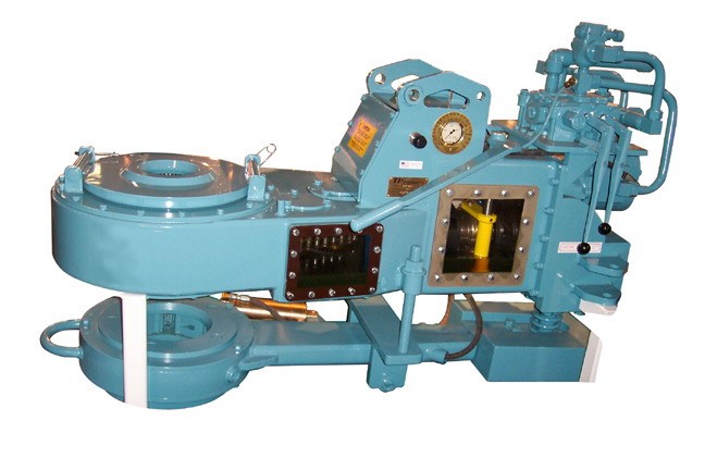
Bulletin 46200eTESCO TOP DRIVESCASING DRILLING ®DRILL PIPE POWER TONGS(CLOSED THROAT)TUBULAR SERVICESAt TESCO, you have a choice of closed throat powertongs manufactured by G.H. Foster, a world leader inpower tongs. Because Foster tongs stay on the pipe theentire trip, your makeup and breakout time is considerablyreduced. And even more importantly, they alsoprotect your pipe and men.All Foster Power Tongs feature:Available Models:Foster Model 97Foster Model 54-02Foster Model 54-93See specifications on reverse.Pressure oil bath lubricationPositive case sealRoller chain final driveHydraulic liftHydraulic clutchSkid mounted T U B U L A R S E R V I C E SThe Drilling Innovation Company www.tescocorp.com

This invention is directed to apparatus and methods for aligning wellbore tubulars; and to power tongs used in making and breaking joints of tubular members such as wellbore casing and tubing; to parts thereof; including, but not limited to gripping elements, and methods of their use.
During the drilling of oil and gas wells and the production of materials therefrom, various operations require the connection and disconnection of successive lengths of threaded tubulars such as pipe, casing, or tubing. Tools known as tongs are used to "make" and "break" such connections. Certain known power tongs have a body, a rotary rotatably mounted in said body and at least one active jaw which, on rotation of the rotary is cammed against a pipe in the rotary and grips it for rotation with the rotary. In known arrangements the camming action is generated by a cam member which is bolted to the rotary and is shaped so that the active jaw is cammed against the pipe on rotation of the rotary relative to the active jaw in one sense and will be released on rotation of the rotary relative to the active jaw in the opposite sense.
With known tongs high torques are applied to tubulars due to combinations of factors such as thread sealing requirements, the presence of corrosion, the existence of distortion, and pipe size and weight. Both in the "make" direction of rotation when a shoulder is suddenly encountered, and in the "break" direction at initial engagement of the tong and disengagement of the threads high shock forces may arise; e.g., with a power-driven tong, in excess of 50,000 foot-pounds of torque may be exerted, while relatively small die elements on jaws of the tong engage the pipe with extremely high force loadings. Slippage occurs and pipe surfaces become marred, marked, indented, or otherwise damaged.
Dies for gripping jaws have been provided with multiple serrations, or penetration features, to provide the interference contact at the joint surface. Grip element penetration into the joint surface is limited and controlled. The distribution and balance of grip element energizing forces are critical factors in the design, development and evaluation of such tong mechanisms. Linkages, levers, wedges, and cams are used to balance force components. Grip elements, or dies, are accurately disposed within carrier bodies, or jaws, which span a circumferential segment of the joint surface.
Uneven die loading can cause excessive indentation, marring or damage to a tubular surface. Drag or braking devices are used in certain tongs to effect proper biting of the dies relative to the pipe. The head or other member supporting the dies is frictionally restrained to insure that the dies do not simply rotate with the rotary as the rotary is driven.
Other tongs use an endless belt, chain or flexible material loop for gripping a tubular. Such tongs are disclosed in U.S. Pat. Nos. 3,799,010; 3,906,820; 3,892,140; 4,079,640; 4,099,479; and 4,212,212. There are a variety of problems associated with certain of these tongs:
Jaw/die tongs and the belt/chain tongs are used with relatively hard and rigid metal tubulars such as casing and tubing. If these tongs are used with thick tubulars or tubulars made from relatively "softer" metals or from premium metals such as high alloy steels or low carbon steels or tubulars made from non-metal materials such as fiber glass, they often literally chew up the tubular. The use of strap wrenches is inadequate since the torque applied with such wrenches cannot be precisely controlled.
Certain tubulars are treated with a rust or corrosion resistant material or coating. If the coating is indented, gouged, or broken, its protective purpose is defeated. Producing enough force in a tong to join such tubulars while not injuring a protective coating presents a dilemma.
The present invention, in certain embodiments, discloses a power tong for joining tubulars so that marking of, indentation of, and surface injury to tubulars are reduced or eliminated. In one aspect a power tong is provided and a method of its use for handling tubulars coated with a corrosion-resistant material which should not be broken or penetrated. In one embodiment such a tong has one or more gripping jaws with gripping elements made of aluminum alloys, zinc, zinc alloys, aluminum, brass, bronze, cermet, plastic, fiberglass, metal alloys, or a combination thereof which present a smooth face (straight or curved) to a tubular without any teeth, pointed projections, or toothed dies. In one aspect the gripping elements are releasably connected directly to jaws. In another aspect the gripping elements are releasably connected to a jacket or holder which itself is releasably connected to a jaw.
In one aspect the cylinder(s) are powered by a small air-driven hydraulic pump with an hydraulic fluid reservoir mounted on a plate on the movable or fixed jaw. Air is supplied to activate a motor of the pump and the pump then provides hydraulic fluid to move a piston of the hydraulic cylinder(s). The motion of the cylinder moves the movable jaw on its roller to travel to a pre-load position on the cam. The cylinder applies pressure until the hydraulic pressure is released. A hydraulic fluid accumulator and a valve may be used to maintain hydraulic pressure at all times so that the cylinder(s) continuously maintain the desired load on the jaw until the air supply to the pump is removed.
In another aspect the cylinders are connected to a rotary of the tong or to any other member that rotates with the rotary rather than to a fixed jaw. Such a pre-load system may, according to this invention, be used with any tong including a tong that does use toothed dies.
In one embodiment the present invention discloses a gripping arrangement for a tong with a sheet of grit which is preferably bonded to a carrier plate. In another embodiment the gripping arrangement comprises a layer of flexible material having a smooth flat surface or a surface with ridges and valleys, for example in the fashion of the surface of a file. The flexible material, in one aspect, is metal, for example sheet aluminum, zinc, brass, bronze, zinc alloy, aluminum alloy, stainless steel, or steel having a thickness of about 1.5 mm. The layer of flexible material may be used in conjunction with a carrier plate or on its own. In a further embodiment the gripping arrangement may comprise a layer of perforate material one of both surfaces of which are preferably coated with grit to facilitate adhesion. The layer will typically be formed from metal having a thickness of about 1.5 mm. The layer may be used in conjunction with a carrier plate or used on its own. In yet another embodiment the gripping arrangement may comprise a layer of expanded mesh, e.g. metal mesh, which has been flattened. One or both surfaces of the expanded mesh may be coated with grit and the layer may be used in conjunction with a carrier plate or used on its own. The grit may comprise, for example, diamond dust, particles of silicon, zircon, tungsten carbide and mixtures thereof. The gripping arrangement may comprise end plates which are attached to the carrier plate. Preferably, the carrier plate is provided with side flanges for insertion into a jaw holder. The present invention also provides a jaw assembly fitted with a gripping arrangement in accordance with the present invention. Preferably, the jaw assembly includes a jaw holder having an arcuate recess which accommodates an arcuate pad of resilient elastomeric material which supports said gripping arrangement. Advantageously, at least one shim is provided which is disposed between said arcuate pad of resilient elastomeric material and said gripping arrangement. The shim will be flexible and generally from 0.5 mm to 1.0 mm thick and made from sheet metal. The present invention also provides a tong fitted with at least two such jaw.
In one embodiment the present invention discloses an apparatus for aligning tubulars and includes a guide on one of a power tong and a backup tong. In one embodiment the apparatus has a socket centralizer mounted on said one of said power tong and said backup tong. In one aspect, said one of said power tong and said backup tong is said power tong. In another embodiment, the apparatus includes a power tong and a backup tong, and the guide is mounted on the power tong and apparatus is provided to maintain the power tong and the backup tong in a certain juxtaposition during a stabbing operation. Preferably, said apparatus includes locating rods on one of the power tong and the backup tong and blocks shaped to receive at least the ends of the locating rods on the other of the power tong and the backup tong. Advantageously, the backup tong is provided with at least two prismatic jaw assemblies to locate the backup tong in fixed juxtaposition with respect to a tubular being gripped.
The present invention, in one aspect, provides a jaw unit for use in a tong, which jaw unit comprises a jaw holder and a jaw movable with respect to said jaw holder, characterized in that said jaw is slidably mounted on said jaw holder. Preferably, said jaw is slidable with respect to said jaw holder about an arcuate path. Advantageously, said jaw has a gripping surface which is substantially arcuate for gripping the surface of a tubular and the center of curvature of such arcuate path lies between the center of curvature of said grip ping surface and said arcuate path. The gripping surface may be a continuous surface or defined by several spaced apart gripping elements. Preferably, the center of curvature of said arcuate path lies between the center of curvature of said grip ping surface and said gripping surface. Advantageously, the center of curvature of said arcuate path is substantially midway between the center of curvature of said gripping surface and said gripping surface. Preferably, one of said jaw and said jaw holder is provided with an arcuate track which defines said arcuate path, and the other of said jaw and said jaw holder is slidably mounted in said arcuate track.
The present invention also provides a jaw assembly comprising two jaw units in accordance with the present invention. Preferably, said jaw units are mounted for pivotal movement about a common pivot shaft. Advantageously, said jaw assembly includes means which bias said jaw units apart. The present invention also provides a rotary fitted with a jaw unit in accordance with the present invention, a rotary fitted with a jaw assembly in accordance with the present invention, and a tong fitted with a rotary in accordance with the present invention.
One of the features of existing tongs is that their rotaries are difficult to furnish. Thus, routine maintenance usually involves dismantling the whole rotary, checking the parts and reassembling the whole. While this is a straightforward procedure in the clean conditions of a workshop it can be problematic when carried out in a muddy field, in sand or in snow. The present invention aims to help solve this problem and provides a rotary which comprises a top section, a bottom section, and a peripheral wall therebetween, characterized in that at least one of said top section and said bottom section is provided with an elongate slot which, when said rotary is in use, accommodates a pivot shaft on which a jaw assembly can be pivotally mounted.
Jaw holders and jaws for tongs are traditionally machined from a solid piece. This is a comparatively expensive procedure. The present invention proposes to make such parts from a stack of individually cut laminations.
Such methods and devices including a power tong with at least one jaw with at least one tubular gripping element having a smooth gripping surface (flat or curved) and, in one aspect, such an element which is flexible;
FIG. 2A is a perspective view of a tubular connection system according to the present invention. FIGS. 2B and 2C are perspective views of a casing tong of the system of FIG. 2A.
FIG. 5A shows schematically an initial position of elements of a tong system according to the present invention. FIG. 5B shows pre-loading on a pipe of the jaws of the system of FIG. 5A. FIG. 5C shows a tubular gripped with the system of FIG. 5A.
FIGS. 1A-1C show a typical prior art power tong that uses fixed jaws and a movable jaw to grip pipe for tubular disconnecting and connecting operations. An outer case houses a powered rotary to which the jaws are mounted. A cam surface of the rotary moves a movable (ACTIVE or MASTER) jaw into (and away from) gripping contact with a tubular, e.g. pipe. Each jaw has toothed gripping inserts to facilitate engagement with the surface of the tubular (see FIG. 1B). FIG. 1C shows the tong in an "OPEN" position in which the tubular is not gripped.
The tong shown in FIG. 1A is a Weatherford Model 14.5-50 High Torque Tong. The brochure "New ! Weatherford Model 14.5-50 High Torque Tong," (1991) and the manual entitled "Model 14.5-50 Hydraulic Power Tong Installation, Operation and Maintenance" (1993) are submitted herewith and incorporated herein fully by reference for all purposes. It is to be understood that the teachings of the present invention are applicable to any tong and any tong system that has one or more gripping elements or jaws and that the Model 14.5-50 tong is shown here for illustrative purposes and not by way of limitation of the scope of the present invention.
As shown in FIG. 2A a system 10 according to the present invention includes a power tong 100 according to the present invention which is like the tong of FIG. 1A but which also includes a unique jaw system 110 with inserts 150 on fixed jaws 120 and insert 152 on movable jaw 122 and at least one jaw pre-load assembly like that shown in FIG. 5A. The system 10 includes a free floating backup tong 12.
As shown in FIGS. 2B and 2C, rods 112 are connected to the movable jaw 122. The inserts 150 are on fixed jaws 120 and the insert 152 is on a movable jaw 122 (corresponding to the fixed jaws and active jaw, respectively, of the tong of FIG. 1A).
FIGS. 4A-4G illustrate an alternative jaw mounting system in which holders are interposed between jaw bodies and inserts. The holders protect the jaws from damage if the inserts wear down and a variety of different types and/or sizes of inserts may be used with and interchanged on a single holder. In one aspect it is within the scope of this invention to use these holders to mount conventional toothed dies to a tong jaw and to use them for easy substitution of new and/or different dies.
FIG. 4A shows a jaw system 400 for a tong (like the tong of FIG. 2A) which has two fixed jaws 402 and a movable (movable toward and away from a tubular to be gripped 403) jaw 404. Each jaw 402 has a jaw body 405 with a holder 406 secured thereto. In one aspect dovetail keys 407 secured to the holder or releasably mounted thereto fit in corresponding slots 408 of the jaw bodies 405 to releasably mount the holder 406 to the body. In one aspect dovetail keys 409 releasably mount the holders 406 to jaw bodies 405. The dovetail keys 409 are releasably held in corresponding recesses 411 in the holders 406. One or more dovetail keys 409 may be used (two shown for each holder 406).
FIG. 5A shows a tong system 500 with a tong having a movable rotary 502, fixed jaws 504, 505, and a movable jaw 506 (remainder of tong, not shown, like the tong of FIG. 2A; like the tong of FIG. 1A, but with the added features discussed here). Pins 520 pin the fixed jaws to the rotary. Inserts 522 on the fixed jaws 504, 505 are like the inserts described herein for other fixed jaws. Insert 524 on the movable jaw 506 is like other inserts described herein for movable jaws. A pre-load cylinder 508 to assist in make-up is pivotably connected at one end to the fixed jaw 505 and at the other end to the movable jaw 506. A pre-load cylinder 510 to assist in break-out is pivotably connected at one end to the fixed jaw 504 and at the other end to the movable jaw 506. It is within the scope of this invention for the ends of cylinders connected to the fixed jaws to instead be secured to the rotary or to a support ring or other member that rotates with the rotary. It is within the scope of this invention to employ one cylinder interchangeable between the positions of the cylinders 508 and 510 (FIG. 5A) or one cylinder connectible to the fixed jaw 506 at one end for break-out and at the other end of the fixed jaw 506 for make-up with the other cylinder end secured to the rotary. Rollers 530 rotatably mounted on the movable jaw 506 co-act with cam surfaces 532 on the rotary 502 to move the jaw 506 to operative and inoperative positions.
Air in a line 640 selectively applied with a control system 650 (e.g. mounted on the rig floor, on the tong or remote controlled) selectively actuates the pump 630 to pump fluid through the valve 602 to the pre-load cylinders. The directional control valve 602 is either manually operated or operated by remote control. Correct fluid pressure is monitored with a gauge 651.
As shown in FIG. 5C the tubular 650 has been gripped due to the action of the pre-load cylinder 510 with a suitable pre-load force (e.g., but not limited to, about 500, 1000, 5000, 10000 or 50000 pounds of force). This force is sufficient that when the rotary 502 of the tong is rotated the jaws do not slip on the tubular 650; but the pre-load force is sufficiently low that the jaws do not mark or damage the tubular 650.
FIG. 8 shows schematically a top view of a power tong according to the present invention. A power tong T has an hydraulic motor M with control/monitor apparatus C on a tong case S. A movable jaw J is moved and rotated by a rotary R which is moved by interconnection, via appropriate gearing, by the motor M. Fixed jaws F and G are secured to the rotary R. A first pre-load cylinder D connects the movable jaw J to the fixed jaw G for applying a pre-load to the movable jaw for make-up operations. A second pre-load cylinder L connects the movable jaw J to the fixed jaw F for applying a pre-load to the movable jaw for break-out operations. An insert I (any insert disclosed herein) is secured to the movable jaw J and inserts K (any insert disclosed herein) are secured to the fixed jaws F and G.
FIG. 9 shows a tong jaw 450 according to the present invention with an insert 454 (any insert disclosed herein) and rods 452 secured thereto, e.g. by welding. The rods 452 provide a member to which either a cylinder body or a piston of a pre-load piston cylinder apparatus is connectible. Instead of the rods 452 as shown which extend from above the jaw 450 to a point below it, only rod sections may be used secured to one or both sides of the jaw to provide a securement member for an end of a pre-load apparatus.
According to the present invention a variety of apparatuses and devices may be employed to pre-load a tong jaw having one or more smooth faced gripping insert elements thereon. In one aspect a manually activated pre-load cylinder is used which has fluid or material manually introduced therein to apply a pre-load or manually removed therefrom to release a pre-load. In another aspect a pre-load cylinder is pivotably secured at one end to a rotary or part thereof and the other end is releasably connectible to either end of a movable jaw so that a pre-load may be applied, selectively, to either end of the movable jaw for make-up or break-out operations as desired. In one aspect such a pre-load cylinder has a rod with an end member receivable in and movable in a slot in the movable jaw or there are recesses at either end of the jaw for holding the end member of the rod so that a pre-load can be applied. A secondary small cylinder may be used to selectively move the pre-load cylinder in the jaw slot or it can be moved manually. In another embodiment the tong"s movable jaw has one or more upwardly projecting lugs engageable by a forked piston rod end of a pre-load piston/cylinder that is attached to the rotary. The rotary is rotated so that the jaw is cammed into the pipe to be rotated in a pre-load position and then the forked rod is removed for further tong operations.
In use, two or more jaw assemblies are placed in a tong and are disposed around a length of casing. The jaw assemblies 1001, 1001" are then advanced radially inwardly in the direction of arrows "A" (FIG. 12) until they engage and firmly grip the casing. Because of the flexible construction of the gripping arrangement 1007, the shims 1006 and the arcuate pad 1004, the friction layer 1009 substantially conforms to the circumference of the casing and grips the casing with a substantially uniform gripping action. Once the casing has been firmly gripped the jaws are rotated by the tong in the usual manner. It will be noted that circumferential forces applied to the friction layer are transmitted through the carrier plate 1008 so that any local loads caused, for example by an irregularity in the surface of the casing are redistributed by the carrier plate 1008 and transmitted to the jaw holder 1002 via the side flange 1011 and the arcuate pad 1004 (see FIG. 18).
Referring to FIGS. 19A and 19B of the drawings there is shown a conventional tong assembly which is generally identified by the reference numeral 2001.
The power tong 2002 comprises a pair of gates 2004, 2005 which are held together in the position shown by latch 2006. When the latch 2006 is released the gates 2004, 2005 can be swung open by admitting hydraulic fluid to piston and cylinder assemblies 2007 and 2008. The power tong 2002 also contains a rotary 2009 which is provided with four jaw assemblies 2010. The rotary 2009 can be rotated by a hydraulic motor 2011.
The backup tong 2003 is provided with two gates 2012, 2013 which are held together by latch 2014 but which, when latch 2014 is released can be swung to an open position.
Once the pin is correctly located the stabbing guide is removed. The gates 2004, 2005 of the power tong 2002 and the gates 2012, 2013 of the backup tong 3 are then opened and the tong assembly 2001 moved towards the casing until the lower length of casing lies within the backup tong 2003 and the upper length of casing lies within the power tong 2002. The gates 2004, 2005, 2012, 2013 are then closed and latched. Jaw assemblies in the backup tong are then advanced to engage the lower length of casing while jaw assemblies in the power tong 2002 are advanced to grip the upper length of casing. The hydraulic motor 2011 is then actuated to turn the rotary 2009 and rotate the upper length of casing relative to the lower length of casing. The tong assembly 2001 is supported by a pneumatic lifting cylinder 2015 which enables the power tong 2002 to move towards the backup tong 2003 as the pin enters the socket. Reaction forces are transmitted by columns 2016 disposed to either side of the tong assembly 2001 and by a series of levers in a known manner. It should be noted that the power tong 2002 is free to move in a plane parallel to the backup tong 2003 within certain limits.
The apparatus 2100 comprises a tong assembly 2101 which is generally similar to the tong assembly 2001 shown in FIGS. 19A and 19B and parts of the tong assembly 2101 similar to the tong assembly 2001 have been identified by similar reference numerals in the "2100" series.
Turning first to the guide 2117 it will be seen from FIG. 21B that this comprises four identical components 2118 which are bolted to the top of the power tong 2102. As best shown in FIG. 21C each component is tapered so as to guide the pin of an upper casing to the center of the opening of the power tong 2102.
Referring now to FIG. 22, the backup tong 2103 is provided with three prismatic jaw assemblies 2119a, 2119b, and 2119c which, when actuated, hold a lower length of casing 2120 in a fixed position relative to the backup tong 2103.
As shown in FIG. 23 the backup tong 2103 is provided with three upwardly extending locating rods 2121 which are each provided with a conical tip 2122. Similar, the underside of the power tong 2102 is provided with three blocks 2123 each of which is provided with a recess 2124 shaped to receive the conical tip 2122 of a respective locating rod 2121.
In use, the lower length of casing 2120 is first secured by slips on the rig floor in the usual manner. The gates 2112 and 2113 of the backup tong 2103 are then opened and the tong assembly 2101 moved into position with the backup tong 2103 circumjacent the lower length of casing 2120 and immediately below the socket 2125 thereof.
The gates 2112 and 2113 are then closed by hydraulic piston and cylinder assemblies 2126 and 2127 and the latch 2114 closed. The prismatic jaw assembly 2119a is fixed while prismatic jaw assemblies 2119b and 2119c are automatically advanced by a predetermined distance when the latch 2114 is closed. This grips the lower length of casing firmly and also ensures that the backup tong 2003 is in a fixed position relative to the lower length of casing 2120. The position thus far attained is shown in FIG. 23.
At this time pneumatic lifting cylinder 2115 is extended which lowers the backup tong 2003. The conical tips 2122 of the locating rods 2121 enter the recesses 2124 of the blocks 2123 and thus locate the power tong 2002 with respect to the backup tong 2003. This in turn locates the guide 2117 with respect to the lower length of casing 2120 so that the center of the guide 2117 is coaxial with the axis of the lower length of casing 2120. This position is shown in FIG. 24.
The power tong 2102 is then raised so that the blocks 2123 are well clear of the locating rods 2121. At this point the jaw assemblies in the power tong 2102 are applied to the upper length of casing 2128 and the hydraulic motor 2111 actuated to rotate the rotary and screw the pin 2129 into the socket 2125. During the procedure the power tong 2102 moves towards the backup tong 2103. However, even when the joint is tightened to the required torque the blocks 2123 still lie a short distance above the conical tips 2122 of the locating rods 2121.
At this stage the jaw assemblies of both the power tong 2102 and the backup tong 2103 are relaxed, the gates 2104, 2105, 2112 and 2113 opened and the tong assembly 2101 retracted in preparation for the casing being lowered. It will be noted that one component 2118 of the guide 2117 is mounted on each of the gates 2104, 2105 and accordingly the guide 2117 opens and closes with the gates 2104, 2105.
For certain applications a backup tong is not required, for example where the power tong can conveniently be restrained by a chain attached to the drilling tower.
The apparatus 2200 comprises a power tong 2202 which is generally similar to the power tong 2002. The basic construction of the power tong 2202 is similar to the power tong 2002 and parts having similar functions have been identified by the same reference numeral in the "2200" series.
The main differences are that the apparatus 2200 does not include a backup tong and that it is provided with a guide 2217 and a socket centralizer 2230.
In use, the lower length of casing 2220 is first secured by slips (not shown) with the socket 2225 facing upwardly close to the slips. The power tong 2202 is then lowered onto the socket 2225 so that the socket 2225 enters the socket centralizer 2230 and aligns the socket centralizer 2230, the socket 2225 and the guide 2217. The upper length of casing 2228 is then lowered so that its pin 2229 enters the guide 2217, is center there by and enters the socket 2225. At this point power tong 2202 is raised. Its jaw assemblies are then advanced to grip the upper length of casing 2228 which is then rotated to screw the pin 2229 into the socket 2225. Once the joint is tightened to the required torque the gates 2204, 2205 are opened and the power tong 2202 withdrawn.
The embodiment shown in FIG. 29 is generally similar to that shown in FIG. 28 except that the apparatus 2300 also includes a backup tong 2303. Since the upper length of casing 2328 and the lower length of casing 2320 are being aligned by the guide 2317 and the socket centralizer 2330 no special arrangements need be made for aligning the power tong 2302 and the backup tong 2303.
The procedure for connecting the upper length of casing 2328 to the lower length of casing 2320 is as follows. First, the lower length of casing 2320 is secured in slip (not shown). The gates 2312, 2313 of the backup tong are then opened and the apparatus 2300 maneuvered so that the lower length of casing 2320 is disposed within the backup tong 2303. The power tong 2302 is then lowered until the socket 2325 on the lower length of casing 2320 is received within the socket centralizer 2330. The upper length of casing 2328 is then lowered until the pin 2329 passes through guide 2317 and enters the socket 2328. Only at this stage are gates 2312, 2313 closed and the jaw assemblies of the backup tong 2303 activated to grip the lower length of casing 2320. The power tong 2302 is then raised and its jaw assemblies activated to grip the upper length of casing 2328 which is then rotated to cause the pin 2329 to enter the socket 2325 and the joint to be tightened to the desired torque. The jaw assemblies are then relaxed and the gates 2304, 2305, 2312, 2313 of the power tong 2302 and the backup tong 2303 opened prior to retracting the apparatus 2300.
Various modifications to the embodiments described are envisaged, for example, if desired, the guide and the socket centralizer could be mounted on the backup tong 2303 rather than the power tong 2302. Alternatively, the guide could be mounted on the backup tong without a socket centralizer. Such an arrangement is shown in FIG. 30.
The embodiment shown in FIG. 30 is generally similar to that shown in FIG. 19a and 19b and parts of the tong assembly 2401 similar to the tong assembly 2001 have been identified by similar reference numerals in the "2400" series. One difference is that the top of the backup tong 2403 is provided with a guide 2417.
In use, the lower length of casing 2420 is first secured by stops 2431 on the rig floor in the usual manner. The gates 2412 and 2413 of the backup tong 2403 are then opened. Since two of the four components 2418 of the guide 2417 are mounted on the gates 2412 and 2413 the guide 2417 opens with the gates 2412 and 2413 so that the lower length of casing 2420 can enter the backup tong 2403 when the carriage 2432 which supports the apparatus 2400 is advanced towards the casing 2420 on rails 2433. When the lower length of casing 2420 is fully within the backup tong 2403 the gates 2412 and 2413 are closed. The components 2418 of the guide 2417 have a stepped interior (not visible in FIG. 30) so that the lower part of each component 2418 touches the socket on the top of the lower length of casing 2420 whilst the upper part of the interior of each component 2418 tapers inwardly to form a funnel. Once the lower length of casing 2420 has been gripped the upper length of casing 2428 is lowered through the power tong 2402 towards the lower length of casing 2420. The guide 2417 guides the pin on the bottom of the upper length of casing 2428 into the socket. The power tong 2402 is disposed a small distance above the guide 2417. Once the pin of the upper length of casing 2428 has entered the socket on the lower length of casing the jaws of the power tong 2402 are applied to the upper length of casing 2428 which is rotated until the joint reaches the desired torque.
Referring now to FIG. 38, the rotary 3100 is shown fitted in a tong 3116. As shown in FIG. 39 and 40, the rotary 3100 is formed as a one piece casting which comprises a top section 3117, a bottom section 3118, and a peripheral wall 3119 on which is formed a toothed track 3120. Both the top section 3117 and the bottom section 3118 are provided with an elongate slot 3121, 3122 respectively. Each elongate slot 3121, 3122 has its center of curvature on the center of rotation of the rotary 3100.
As can be seen in FIG. 38 and FIGS. 31 to 37, the sides of the rotary 3100 are provided with cams 3128, 3129, 3130 and 3131 which are screwed to the rotary 3100. The rotary 3100 is located in the tong 3116 by nine guide rolls 3132, five of which are visible in FIG. 38. The guide rolls 3132 each have an upper and a lower roller which bears against the peripheral wall 3119 of the rotary 3100 above and below the toothed track 3120 respectively.
[0001] This invention relates to a power tong and jaw apparatus, especially for a gripping pipe, of the type having a stationary housing with a central opening for receiving pipe to be gripped, a ring gear rotatably mounted in said housing for movement about said central opening, a plurality of jaws supported by said housing and movable between an extended position for gripping pipe in said central opening and a retracted position, said jaws being rotatably engaged by said ring gear, and drive means for transmitting rotary motion to said ring gear.
[0002] This application is related to the application of Kerry Kennington and Ronald Baker, entitled "REVERSAL MECHANISM FOR POWER TONG", having an attorney docket number 80507, filed concurrently herewith.
[0003] Power tongs associated with well drilling work are well known in the art. Such prior tongs have generally been classified as either open head or closed head tongs. A lateral passageway is provided in the open head tong which allows the pipe to be engaged or disengaged by moving the tong laterally with respect to the vertical pipe axis. The closed head tong, being formed in the shape of a closed circle, can only be installed on the pipe by lowering the tong over the pipe while the pipe is held by slips at the rig floor. The power tong shown in U.S.Patent No. 1,811,666 to W.W. Foster, issued June 23, 193


 8613371530291