
gill power tong free sample

Model 500 Serial No.________________________Customer Reference No._____________________Gill Services, Inc. 650 Aldine Bender, Houston, TX 77060Phone: 281-820-5400 Fax: 281-820-0034 Website: www.gillservicesinc.com
IMPORTANT SAFETY NOTICEProper service and repair is important to the safe, reliable operation of all GILL SERVICESequipment. The service procedures recommended by GILL SERVICES and described in thetechnical manuals are recommended methods of performing service operations. Some of theseservice operations require the use of tools especially designed for the purpose. The special toolsshould be used when and as recommended.It is important to note that some warnings against the use of specific service methods that candamage the equipment or render it unsafe are stated in the manuals. It is also important tounderstand that these warnings are not exclusive. GILL SERVICES could not possibly know,evaluate, and advise the service people of all conceivable ways in which service might be done orof the possible hazardous consequences of each way. Accordingly, anyone who uses serviceprocedures or tools which are not recommended by GILL SERVICES must first satisfy himselfthoroughly that neither his safety nor his equipments safety will be jeopardized by the methodselected.
WARRANTY AND GUARANTEEGILL SERVICES, INC. warrants and guarantees that all equipment furnished hereunder andmanufactured or reconditioned by GILL SERVICES, INC. (hereinafter called Vendor) iswarranted to be free from defects in workmanship and material for a warranty period of six (6)months from date of receipt of the original retail purchaser. If, under normal use and service, anyfailure of any parts by reason of a defect in workmanship or material shall appear within suchwarranty period, Purchaser shall notify Vendor thereof immediately, and if so requested byVendor, shall return the defective part to Vendor, transportation charges prepaid, and Vendorshall, upon verifying that the cause of the failure is within the terms hereof, correct any suchdefects by repairing the defective part at its works or by supplying a replacement thereof F.O.B.Vendors works or warehouse. This guarantee does not apply to any parts or items thereof whichshall have been repaired or altered by other than Vendor in any way so as, in Vendors judgment,to affect same or which has been subjected to negligence, accident or other than normal use andservice. The liability of Vendor arising out of the supplying of any material hereunder or its use,whether on warranties or otherwise, shall not exceed the cost of correcting defects as hereinprovided, and shall not include transportation charges, Purchasers labor or materials (except asauthorized in wiring in advance), loss of use or revenue, or any indirect or consequentialdamages. Upon expiration of said warranty period, all such liability shall terminate. Vendorshall have no liability, other than as specifically herein provided, upon warranties, expressed orimplied, of any nature whatsoever, (exclusive, however, of its warranty of title) including, butwithout limitation, warranties with respect to workmanship, material performance and fitness foruse. Upon the expiration of said six (6) month period after the original receipt to retail purchaserof the machinery, all liability hereunder with respect to the machinery or any part or parts thereofrepaired or replaced by reason of this guarantee shall terminate. Any parts or material not ofVendors manufacture is covered only to the extent of any guarantee given to the Vendor by theseller of said material and enforceable by the Vendor against said seller.
WARNINGDO NOT OPERATE, ADJUST, OR REPAIR THIS TONGWITHOUT PROPER TRAINING. READ AND UNDERSTAND ALLOPERATING AND MAINTENANCE INSTRUCTIONS AND ALLOTHER WARNINGS CONCERNING SAFETY BEFORE USINGTHIS TONG. DO NOT REMOVE OR PAINT OVER WARNINGLABELS.
1. DO NOT OPERATE TONG UNTIL ANCHOR ARM ISATTACHED TO THE TONG AND ANCHOR POST.2. DO NOT CRAWL OR STAND UNDER TONG.3. CAUTION: KEEP HANDS CLEAR OF TONG HEADWHILE TONG IS IN OPERATION, AS PARTS INSIDETONG HEAD ROTATE. KEEP ALL PARTS OF THEBODY AND CLOTHING AWAY FROM MOVINGPARTS.4. SHUT OFF POWER SUPPLY TO THIS UNIT BEFOREPERFORMING ANY WORK, (i.e., CHANGING TONGDIES OR JAWS, ADJUSTMENTS, MAINTENANCE,OR LUBRICATION).5. FAILURE TO COMPY WITH WARNINGS COULDRESULT IN EQUIPMENT DAMAGE ANDPERSONAL INJURY.
1. INTRODUCTIONThis manual contains information regarding the GILL Model 500 Power Tong. Full benefitof long life and dependability of this unit can only be realized by proper operation andmaintenance. The operator should familiarize himself thoroughly with informationcontained in this manual before operating this tong. GILL SERVICES, INC. provides theinformation, data, and recommendations contained in this manual as a customer service. Allare believed accurate. However, GILL SERVICES, INC. assumes no responsibility, impliedor otherwise, for errors in or for the application of the Information, data, andrecommendations presented herein.The right is reserved to make changes in this manual at any time, without obligation.
WARRANTY..WARNING INTRODUCTION .GENERAL DESCRIPTION TORQUE CURVE ...SPECIFICATIONS ..INSTALLATION AND OPERATION INSTRUCTIONS ..VICKERS HYDRAULIC FLUID RECOMMENDATIONSLUBRICATION AND MAINTENANCE .FINAL DRIVE ASSEMBLY TRANSMISSION ASSEMBLY ..JAW SETS LISTS ...TONG DRAG RING ASSEMBLY .CLUTCH ASSEMBLY .HYDRAULIC LIFT ASSEMBLY ..COMMERCIAL HYDRAULICS ..HYDRAULIC TORQUE GAUGE ASSEMBLY ..BACKUP TOOL ...AIR CONTROLS FOR BACKUP TOOL ....MAINTENANCE LOG..
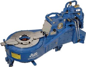
2. GENERAL DESCRIPTIONGILL MODEL 500 Power Tong is a safe and accurate unit for the makeup andbreakout of tubing and casing 1-5/16 in O.D. through 7 in O.D. These power tongfeatures include: closed head design, allowing tong to remain in position duringthe entire trip, reducing makeup and break-out time; pressure oil bathlubrication; positive case seal; direct motor drive; roller chain final drive; twospeed operation; controlled torque; and stiff torque arm for safety.
RPMHigh Gear.*126Low Gear...*27Hydraulic Requirement..33 GPM at 2,000 psiTong Length.51Space Required on PipeTong.9-1/2 inWith backup.....16-1/2 inMaximum Elevator Diameter Clearance...30Approximate WeightTong...1,000 lb* (RPM based on published requirements of motor manufacturer: 33.5GPM to tong motor5. INSTALLATION AND OPERATION INSTRUCTIONS5.1 INSTALLING WITH SPRING CUSHIONED HYDRAULIC LIFT1. Move tong to convenient position near well.2. Lift hydraulic cylinder, set in position on tong, attach with pins, and connecthydraulic line from control valve to cylinder.3. Lift tong with line approximately 3 feet above well head. (Cylinder has 6 foottravel.) The hydraulic lift is ready to operate by means of controls. The linesupporting the tong should be located so the tong head will hang over the center ofthe well.4. Weld anchor bracket on right rear corner of rig approximately 4 feet aboveground. Additional anchor brackets can be purchased for use of this tong on morethan one rig. See Figure 5-1.5. Connect torque arm to rear of tong and to anchor bracket on rig. The torquearm Is adjustable, so adjust the torque arm so that the tong will be at a right angle totorque arm. See Figure 5-2. Tong should then have about 4 feet of free verticaltravel. Lower tong over tubing.6. Attach hoses from hydraulic power source. Be sure all self-sealing hosecouplings are tight before starting engine. Tighten firmly by hand. Failure to do thiswill cause engine to run at full speed when tong is not in use.7. To level tong, use the leveling screws and compression spring nuts. If tong isnot level, it will cause excessive wear to tong jaws and Inserts. See Figure 5-3.
1. For breaking out and/or making up joints, place jaws on pins withlong side of jaw against gear teeth.2. Inserts are reversible and should be turned around when theybecome worn or replaced if reversing fails to bring sharp teethIn contact with pipe.5.3 SETTING HYDRAULICS FOR PROPER OPERATION1. Check all hose connections before engaging hydraulic powersource.2.
Adjust tong relief valve. The relief valve on the tong operatesin makeup direction only.a. Turn relief valve adjusting screw to left toreduce pressure until tong reduces speed.b. Place tong on tubing to be made up andgradually increase the pressure to reach make uprequired. Check manufacturers recommendedmakeup torque for type of joint beingmade up.c. Lock relief valve adjusting screw and make upsecond joint checking torque where tong stalls.d. Make minor corrections as necessary untiltorque readings are satisfactory.e. If tong grips and slips, increase pressure ondrag plugs by screwing in drag screws in dragring. Adjust screws evenly. See Figure 5-4.NOTE: It is not necessary to change makeup torque to
break-out. Tong operates at system pressure for breakout.System pressure is controlled by a relief valve set at 2200PSI in power unit tank. PSI should not exceed 2500 PSL4. If pump fails to pick up oil after hoses have been connected orif tong runs in surges, screw out relief valve all the way and letpressure back to tank. Circulate to remove air. Screw In pressurescrew until tong operates. Repeat if necessary.5. In operating tong, stop operating lever in center position onesecond before reversing motor. This reduces fluid shock Inmotor.
5.4 STEPS TO DISMANTLE1. Raise tong to top of hydraulic lift travel.2. Use a line to lower tong and hydraulic lift to ground.3. Shut off hydraulic source to tong. Engage lever on control valve for lift to release pressure off lifthose.4. Disconnect hoses and prepare unit for transporting.
6. VICKERS HYDRAULIC FLUID RECOMMENDATIONS6.1 OIL-TYPEOils used in hydraulic systems perform the dual function of lubrication and transmission of power.Oil must be selected with care and with the assistance of a reputable supplier.Crankcase oils meeting or exceeding the Five Engine Test Sequence for evaluating oils for API(American Petroleum Institute) service MS (Maximum Severity) best serve the needs of mobilehydraulic systems. These engine sequence tests were adopted by the Society of AutomotiveEngineers, American Society for Testing Materials, and automotive engine builders. The MSclassification is the key to selection of oils containing the type of compounding that will extend theoperating life of the hydraulic system. Oils meeting Diesel engine requirements, DG through DSclassifications, may or may not have the type of compounding desired for high performancehydraulic systems.HYDRAULIC SYSTEMOPERATING RANGE(Mm. to Max.)0F to 180F15F to 210F32F to 230F0F to 210F
Automatic Transmission Fluid, Type A, is usually satisfactory for power steeringsystems or those systems operating under moderate hydraulic service.6.2 OPERATING TEMPERATURESThese temperature ranges for each grade of oil are satisfactory If suitable proceduresare followed for low temperature start-up conditions and if sustained operation isavoided at the upper temperature limits. Operation in excess of these temperaturesresults in increased wear of the system components and causes more rapiddeterioration of the oil. For optimum operation, a maximum oil viscosity of 4,000 SSUat the low temperature start-up condition and a minimum oil viscosity of 60 SSU for thesustained high temperature operating condition are recommended.Good oils are the most economical. Specifications can be set up which will indicate, toa limited degree, the characteristics essential in a good hydraulic oil. These are listedherein and should be checked with the oil manufacturer prior to the use of theirproduct.
7.2 OPERATIONAL MAINTENANCE1. Grease lube fittings weekly, (Fig. 7-1).2. Check the transmission after every trip. If water or dirt is found in transmission, change oil. Undernormal conditions, oil should be changed every 100 work-hours.3. Clean and grease tong head and backup tool after every trip. Use kerosene or solvent and a wirebrush for cleaning. After cleaning, applycup grease to jaws, pins, ring gear, and top seal.4. Do not steam clean tong head. Steam cleaning tong head will force water by the top seal Into thetransmission, removing all of the lubricants from top seal and causing It to harden. If steam cleaning isused, guide bell should be pinned in place. After cleaning, check the transmission for the presence ofwater.7.3 SAFETY POINTS AND WARNINGSCAUTION: Keep hands clear of Tong Head while Tongs are in operation. Caution should be taken whi!e operating thisequipment, as parts inside the Tong Head rotate.1. Do not crawl or stand under Tongs as hydraulic line could be cut or broken, and Tongs will fall.2. Do not operate Power Tongs until the Anchor Arm is attached to the Tong and Anchor Post.3. Power should be OFF before any size equipment change, maintenance, or any work Is done to thisequipment.
13. CLUTCH13.1 Adjustment For Clutch1. Remove side panel from operators side of tong.2. Be sure tong is in neutral position.3. Rotate clutch with hand until slot in adjusting collar is facing toward the opening in tong.4. Insert screwdriver or similar object in slot in the adjusting collar.5. Pry the adjusting collar away from pressure plate so that the teeth are free from each other.6. Rotate adjusting collar in the direction shown to adjust clutch.7. Follow the above procedure for both ends of the clutch.8. Adjust left end of clutch for high gear.9. Adjust right end of clutch for low gear.10. If the clutch slips or the disc stack heats up, adjustment is required.

Gill Services, Inc. 650 Aldine Bender, Houston, TX 77060 Phone: 281-820-5400 Fax: 281-820-0034 Website: www.gillservicesinc.com GILL SERVICES, INC. GILL MODEL 300M ROD TONG
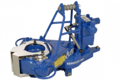
High range has 95 RPM with 850 ft.-lbs. of torque, while low range has in excess of2300 ft.-lbs. of torque. An adjustable relief valve (conveniently located on top of thetong) sets the torque desired.
This tong is positioned by a rigid torque arm. The tong jaws engage the rod squareautomatically. Release is automatic by reversing tong. Gill Services, Inc. Model 300M Power Tong
2000 1025 1341 2366Model 300M Rod TongGill Model 300M Rod TongInner Ring Assemblies and Back-Up Wrenches, Sucker Rods
BG27894 1 Inner Ring, 1-1/8”BG27905 2 Jaw, 1-1/8”BG27897 2 Jaw SpringBG27722 2 Jaw Hinge PinBG27907 1 Back-Up Wrench, 1-1/8” Rod Gill Services, Inc. Model 300M Power Tong Installation
Hang the tong on a suitable line (usually a 9/16” Connect the hoses with the power hose on the 1” topwire rope) from a point high enough to allow the connection; and the return line to the 1-1/4” bottomtong to swing easily. The tong may be hung over a connection.sheave either on a fixed line or a counter-weightedline. There is a spring in the suspension assembly SELF-SEALING COUPLINGSthat will allow the tong to move vertically while thejoint is being made up or broken out, even if thetong is suspended on a fixed line. IMPORTANT: Check all hoses to make certain that the self-sealing couplings are completely engaged and the hydraulic system is not blocked inBALANCE ADJUSTMENT any way.
With the tong on the rod, adjust the leveling screw at HYDRAULIC OILthe top of the hanger so the tong hangs perfectlylevel while threading rods. Adjust the height of thetong so the jaws in the inner ring are the same height Check the oil tank level to ensure that there is plentyas the top square of the rods. Adjust turnbuckle as of oil in the system. With the hoses properly hookedneeded to level tong front to back while on rod. up to the tong, engage the pump and allow the oil to circulate for a few minutes to warm up the tong before full operation. In cold weather, allow timeINNER RING for warm-up as you would for an internal combustion engine.Check the inner ring (jaw assembly) for size and ro-tation. Instructions for removal and installation of CAUTION: As with any tool, the Gill Modelthe inner ring are included in this manual. 300M Rod Tong must be handled with care. Make no adjustments while hydraulic power isBACK-UP WRENCH connected. Keep fingers and hands out of rotating jaw areas.Check the back-up wrench for size. One back-upwrench fits both 3/4” and 7/8” rods. All other back- WARNING: This product could be hazardous ifup wrenches fit only one specific rod size. improperly used. Misuse of this tool could cause serious injury to personnel. This tool must be properly installed and maintained. Do notInstall the back-up wrench so it hangs on the back- remove or alter any parts. Do not weld or alterup wrench support spring. without factory authorization. All replacement parts must be of Gill Services, Inc. manufacture. Gill Services, Inc. Model 300M Power TongOperation TroubleshootingCHANGING DIRECTION OF ROTATION JUMPING OUT OF TIME
Determining Direction of Rotation: The inner ring The tong can jump out of time if the brake coverrotates a rod in the direction indicated on the top and plate becomes loose, allowing the brake drum tobottom of the assembly, just opposite the opening. disengage from the inner ring. This problem can alsoThe side marked “MAKE” is for making up rods. occur if the brake drum pins have worn down orThe side marked “BREAK” is for breaking out rods. moved down until they are too short. Turn the pins down and drive them back into place, or replaceINNER RINGS WITH INDEXING KNOB. them with new pins. The pins should extend 1/2”Rod tong inner rings have an indexing knob on the above the brake drum.side. Its purpose is to prevent installing the innerring upside down or out of phase with the outer ring. JAWS FAIL TO ACTUATEThe knob makes it necessary to line up the openingof the inner ring with the opening in the frame, asdescribed below. This is caused by a worn out brake band, by interference between the jaws and the inner or outer ring, or both.REMOVING THE INNER RING. Rotate thetong to close the jaws, and stop the rotation when the If there is interference between the jaws and theopening of the inner ring is 90 degrees from the outer ring, something is probably holding the inneropening in the frame. Next, reverse the rotation ring too high, causing the jaws to hit or drag theenough to free the inner ring from the resisting force inside top of the outer ring. This can be caused by:of the brake. The amount of travel is equivalent toabout one tooth on the outer ring. The inner ring isthen free to be lifted out. 1. The brake drum not being down against the brake cover plate;NOTE: DISCONNECT HYDRAULIC HOSESBEFORE REMOVING INNER RING, AND 2. A brake drum pin sticking up too high; orUSE INNER RING SAFETY TOOL TOREMOVE INNER RING. 3. A jaw pin not evenly spaced in the inner ring, causing the brake drum pin to contactREPOSITIONING INNER & OUTER RINGS it.
1. After removing the inner ring, turn it over. Foreign matter between the brake drum and the inner DO NOT ROTATE IT. ring can also cause jaw failure. A loose brake cover 2. Rotate the outer ring halfway around (180 plate could also prevent proper actuation of the jaws, degrees). Carefully line up the outer ring by letting the inner ring set too low. A worn out roller in the middle of the brake drum brake band can also cause jaws to fail. opening. Note that outer ring roller is in the middle of both brake drum and frame openings. 3. Replace the inner ring. Line up the opening of the inner ring with the brake drum opening. 4. When the inner ring is in place it will drop down over the brake drum pins, and this will verify correct installation of the inner ring. Model 300M Rod Tong Use, Care & Handling Sucker Rod Joint Makeup Utilizing Circumferential Displacement
General 4.1 For optimum performance it is imperative that all of the jointsin the string of rods to be made up to a given preload stress levelin order to prevent separation between the pin shoulder and thecoupling face during the pumping cycle. __ ________________________________________________ 4.2 There are many inherent variables which affect joint makeup. 1 2 3Among these are the differences in materials, the smoothness of ________________________________________________surface finishes and the lubricity of lubricants, as well as theoperating characteristics and mechanical condition of the power Running New Rerunningtong equipment. As a result, applied torque has not proven to be Grade D Grades C, D, & Kthe most accurate, nor the most practical means of measuring the Displacement Values Displacement Valuespreload stress level in a sucker rod joint. Rod Size Minimum Maximum Minimum Maximum ½ 6/32 8/32 4/32 6/32 4.3 Both test data and theoretical calculations show thatcircumferential displacement beyond handtight makeup of coupling 5/8 8/32 9/32 6/32 8/32and pin provides an accurate and repeatable means with which tomeasure and define the preload stress in a sucker rod joint. 4.4 In view of the foregoing, this recommended practice ¾ 9/32 11/32 7/32 17/64provides, for field use, a comprehensive set of circumferential 7/8 11/32 12/32 9/32 23/64displacement values and procedures covering their use, includinga method for the calibration of power tongs. 4.5 Circumferential Displacement Values. Circumferential 1 14/32 16/32 12/32 14/32displacement as used herein is the distance measured, after 1 1/8 18/32 21/32 16/32 19/32makeup, between the displaced parts of a vertical line scribedacross the external surfaces of the box and pin when they are in a _________________________________________________shouldered hand-tight relationship prior to makeup. NOTE: Above displacement values were established through 4.6 The circumferential displacement values shown in Table 4.1 calculations and strain gauge tests.are the necessary and recommended displacements required to General Recommendations, Power Tongsachieve an optimum preload stress. Values for a combination ofmaterials and their application are listed in the column headings. 4.10 The use of air or hydraulic power rod wrenches isChoose the correct column. recommended to assure best makeup results for all sizes of 4.7 Because the interface surfaces of the joint are burnished or rods. However, it is imperative that the power wrenches besmoothed out on initial makeup, the displacement values on the maintained in accordance with our recommendations.initial makeup are greater than those on subsequent makeup. 4.11 When using power wrenches, it is recommended thatWhile this difference is displacement occurs in varying degrees the hydraulic power oil system be circulated until a normalwith all rod grades, it is observed to be consistent only in the operating temperature is reaches and that this temperatureGrade D rod. Notice, the tabulated values for use when rerunning be maintained within a reasonable level through calibrationGrade D rods are smaller than those for the initial makeup of new and installation of rods.Grade D rods. 4.8 It is impractical to establish displacement values for the initial Calibration of Power Tongmakeup of Grade C and K rods, because of the inconsistency ofobserved test data with these materials. It is therefore 4.12 Power tong must be calibrated to producerecommended that new Grade C and K rod joints be made up and recommended circumferential displacement makeup valuesbroken, in the field, prior to final makeup on initial installation. shown by Table 4.1. After initial calibration, it is 4.9 When new couplings are installed on previously used rods recommended that the power tong calibration be checkedregardless of their grade, the displacement values listed in Table each 1000 feet and be recalibrated for each rod size change.4.1, Column 3, should be used. TABLE 4.1 SUCKER ROD JOINT CIRCUMFERENTIAL *Contact your rod manufacturer for specific make-up of brand DISPLACEMENT VALUES of Rod being used. All dimensions in inches Model 300M Rod Tong Use, Care & Handling Calibration of Power Tongs for rerunning of all 4.13 There are three different methods employed in calibrating Grades of API Rods and New Couplingspower tongs for various API Grade rods and field conditions. It isimperative to select the recommended method to suit your fieldconditions. j. Employ values shown in Table 4.1, Column 3 and follow same procedure as outlined in Par. 4.13,Calibration of Power Tongs for NEW API Grade D Rods steps a through g.
a. Check condition outlined under Par. 4.1. Use of Rod Wrenches for Manual Make-up b. Set the tongs operating pressure on the low side of the estimated value required to produce prescribed 4.14 The use of rod wrenches is not recommended for rod circumferential displacement value shown by Table 4.1. sizes larger than ¾ inch. Application of rod wrenches c. Screw the first joint together hand-tight, scribe a fine vertical to achieve the desired preload is as follows: line across the pin and coupling shoulder to establish hand- tight reference as shown by Fit. 4.1. Manual Make-up of New API Grade D Rod Strings d. Loosen coupling to normal running position, then make up joint with power tong operating with the tong throttle a. Screw rod and coupling to a shouldered hand- depressed to the fully open position. Do not hit the throttle a tight position. second time after joint shoulder and tongs have stalled. b. Scribe a fine vertical line across the pin and e. Remove the tongs and measure the circumferential coupling to establish a hand-tight reference as displacement between the scribed hand-tight vertical line as shown by Fig. 4.1. shown by Fig. 4.2 c. Apply necessary mechanical force to achieve f. Increase or decrease the tong operating pressure to recommended displacement values as shown in achieve the selected prescribed circumferential Table 4.1, Column 3. displacement as shown by Table 4.1. g. Repeata Steps d. through f. until proper displacement is Mechanical Make-up of API Grade C and Grade K Rods achieved. Check calibration of tongs a minimum of 4 joints d. Apply mechanical force and makeup joint once. and for each 1000 feet thereafter and at each change in rod Loosen and retighten to hand-tight position. sizes. e. Scribe a fine vertical line across the pin andCalibration of Power Tongs for API Grade C & Grade K Rods coupling shoulder to establish a hand-tight reference as shown by Fig. 4.1. h. For the initial run of API Grade C and Grace K Rods, a f. Apply necessary mechanical force to achieve constant correction factor cannot be recommended recommended displacement values as shown in because of inherent variables involved. Therefore, it is Fig. 4.1, Column 3. imperative to make up and break the connection prior to calibration of power tongs if proper preload is to be assured. Mechanical Make-up of Used Rods and New Couplings i. Once the joint is made up and broken, follow the same g. Bring coupling and rod pin to a hand-tight procedure as outlined in Par. 4.13, steps a. through g., position. using the appropriate circumferential displacement values in h. Scribe a find vertical line across the pin and Table 4.1, Column 3. coupling shoulder to establish a hand-tight reference as shown by Fig. 4.1. i. Apply mechanical force sufficient to achieve circumferential displacement as shown in Table 4.1, Column 3.

A two-speed Hydra-Shift® motor coupled with a two-speed gear train provides (4) torque levels and (4) RPM speeds. Easily shift the hydraulic motor in low speed to high speed without stopping the tong or tublar rotation, saving rig time.
A patented door locking system (US Patent 6,279,426) for Eckel tongs that allows for latchless locking of the tong door. The tong door swings easily open and closed and locks when torque
is applied to the tong. When safety is important this locking mechanism combined with our safety door interlock provides unparalleled safety while speeding up the turn around time between connections. The Radial Door Lock is patented protected in the following countries: Canada, Germany, Norway, United Kingdom, and the United States.
The field proven Tri-Grip® Backup features a three head design that encompasses the tubular that applies an evenly distributed gripping force. The Tri-Grip®Backup provides exceptional gripping capabilities with either Eckel True Grit® dies or Pyramid Fine Tooth dies. The hydraulic backup is suspended at an adjustable level below the power tong by means of three hanger legs and allowing the backup to remain stationary while the power tong moves vertically to compensate for thread travel of the connection.
The Model 300 Sucker Rod Tongs made to make getting on and off the rods easier and to reduce weariness and mishaps. The Model 300 accelerates tripping the pipe, protects rods, and all while simply using the same power unit as a tubing tong. The Model 300 comes with a modifiable relief valve to set the torque; 95 RPM and 850ft/lbs. of torque at high range. Situated by a firm torque arm, this tong can engage automatically and release automatically by a reversing tong.
The Model 300M Sucker Rod Tongs made to make getting on and off the rods easier and to reduce weariness and mishaps. The Model 300 accelerates tripping the pipe, protects rods, and all while simply using the same power unit as a tubing tong. The Model 300 comes with a modifiable relief valve to set the torque; 95 RPM and 850ft/lbs. of torque at high range. Situated by a firm torque arm, this tong can engage automatically and release automatically by a reversing tong. A feature unique to this model is the ability to breakout and make-up 1-1/8” rods without over torqueing.
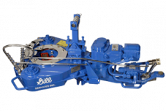
The Model 500 Power Tubing Tong has a size range of 1-5/16” to 7”, joint make-up in 5 seconds, and joint break-out in 7 seconds. With a split glide ring, both safer and more convenient access to jaws and final drive gear components is attainable, while pressurized oil baths ensure that the Model 500 is properly lubricated. The Model 500 also features an adjustable clutch and air or hydraulic assist for the back-up tool. Also fitted with a “Power Shift” Transmission, the operator is able to adjust gears during operation while the Improved Drive Alignment minimizes wasted power.
The Model 600 Power Tubing Tongs feature an adjustable clutch and is available in either air or hydraulic assist for the back-up tool. Also fitted with a “Power Shift” Transmission, the operator is able to adjust gears during operation while the Improved Drive Alignment minimizes wasted power. The Model 600 permits joint make-up in 5 seconds and joint break-out in 7 seconds. With a split glide ring, both safer and more convenient access to jaws and final drive gear components is attainable, while pressurized oil baths ensure that the Model 500 is properly lubricated.
The Model RSHD Power Tubing Tongs are truly a heavy duty piece of equipment that is for the tough jobs. The Model RSHD has more steel weight and gussets added to the bottom in order to diminish chance of case spreading. This model features a customary chain-driven design, integral sprocket, and outer ring. Lastly, the Model RSHD utilizes a familiar jaw-and-bushing biting system.
The Model 700 features the highest torque of all the Power Tubing/Casing Tongs at 20,000 ft./lbs. at 2000 PSI. This model consists of a light drill pipe, tubing, and casing.
Contact our expert sales staff for pricing, availability and product specifications for the Gill Power Tong right for your application at the link provided on this page.
13. Zucca N, Erriu G, Onnis S, Longoni A. An analytical expression of the output of a power-compensated DSC in a wide temperature range. Thermochim Acta 2002;143:117–125
57. Tello-Solìs SR, Hernández-Arana A. Effects of irreversibility on the thermodynamic characterization of the thermal denaturation of Aspergillus saitoi acid proteinase. J Biochem 1995;311:969–974 PubMed]
148. Zhang H, Tong S-Y, Zhang X-Z, Cheng S-X, Zhuo R-X, Li H. Novel solvent-free methods for fabrication of nano- and microsphere drug delivery systems from functional biodegradable polymers. J Phys Chem C 2007;111:12681–12685
168. Gill P, Alvandi A-H, Abdul-Tehrani H, Sadeghizadeh M. Colorimetric detection of Helicobacter pylori DNA using isothermal helicase-dependent amplification and gold nanoparticle probes. Diagn Micr Infec Dis 2008;62:119–124 [PubMed]
169. Gill P, Ghalami M, Ghaemi A, Mosavari N, Abdul-Tehrani H, Sadeghizadeh M. Nanodiagnostic method for colorimetric detection of Mycobacterium tuberculosis 16S rRNA. Nanobiotechnol 2008;4:28–35
270. Vanden Poel G, Mathot VBF. High performance differential scanning calorimetry (HPer DSC): a powerful analytical tool for the study of the metastability of polymers. Thermochim Acta 2007;461:107–121
272. Gabbott P, Clarke P, Mann T, Royall P, Shergill S. A high-sensitivity, high-speed DSC technique: measurement of amorphous lactose. Am Lab 2003;35:17–22
277. Pijpers MFJ, Mathot VBF. Optimization of instrument response and resolution of standard- and high-speed power compensation DSC. J Therm Anal Calorim 2008;93:319–327
280. Saunders M, Podluii K, Shergill S, Buckton G, Royall P. The potential of high speed DSC (Hyper-DSC) for the detection and quantification of small amounts of amorphous content in predominantly crystalline samples. Int J Pharm 2004;274: 35–40 [PubMed]
283. Maghami P, Ranjbar B, Hosseinkhani S, Ghasemi A, Moradi A, Gill P. Relationship between stability and bioluminescence color of firefly luciferase. Photochem Photobiol Sci 2010;9:376–383 [PubMed]

This invention is directed to apparatus and methods for aligning wellbore tubulars; and to power tongs used in making and breaking joints of tubular members such as wellbore casing and tubing; to parts thereof; including, but not limited to gripping elements, and methods of their use.
During the drilling of oil and gas wells and the production of materials therefrom, various operations require the connection and disconnection of successive lengths of threaded tubulars such as pipe, casing, or tubing. Tools known as tongs are used to "make" and "break" such connections. Certain known power tongs have a body, a rotary rotatably mounted in said body and at least one active jaw which, on rotation of the rotary is cammed against a pipe in the rotary and grips it for rotation with the rotary. In known arrangements the camming action is generated by a cam member which is bolted to the rotary and is shaped so that the active jaw is cammed against the pipe on rotation of the rotary relative to the active jaw in one sense and will be released on rotation of the rotary relative to the active jaw in the opposite sense.
With known tongs high torques are applied to tubulars due to combinations of factors such as thread sealing requirements, the presence of corrosion, the existence of distortion, and pipe size and weight. Both in the "make" direction of rotation when a shoulder is suddenly encountered, and in the "break" direction at initial engagement of the tong and disengagement of the threads high shock forces may arise; e.g., with a power-driven tong, in excess of 50,000 foot-pounds of torque may be exerted, while relatively small die elements on jaws of the tong engage the pipe with extremely high force loadings. Slippage occurs and pipe surfaces become marred, marked, indented, or otherwise damaged.
Dies for gripping jaws have been provided with multiple serrations, or penetration features, to provide the interference contact at the joint surface. Grip element penetration into the joint surface is limited and controlled. The distribution and balance of grip element energizing forces are critical factors in the design, development and evaluation of such tong mechanisms. Linkages, levers, wedges, and cams are used to balance force components. Grip elements, or dies, are accurately disposed within carrier bodies, or jaws, which span a circumferential segment of the joint surface.
Uneven die loading can cause excessive indentation, marring or damage to a tubular surface. Drag or braking devices are used in certain tongs to effect proper biting of the dies relative to the pipe. The head or other member supporting the dies is frictionally restrained to insure that the dies do not simply rotate with the rotary as the rotary is driven.
Other tongs use an endless belt, chain or flexible material loop for gripping a tubular. Such tongs are disclosed in U.S. Pat. Nos. 3,799,010; 3,906,820; 3,892,140; 4,079,640; 4,099,479; and 4,212,212. There are a variety of problems associated with certain of these tongs:
Jaw/die tongs and the belt/chain tongs are used with relatively hard and rigid metal tubulars such as casing and tubing. If these tongs are used with thick tubulars or tubulars made from relatively "softer" metals or from premium metals such as high alloy steels or low carbon steels or tubulars made from non-metal materials such as fiber glass, they often literally chew up the tubular. The use of strap wrenches is inadequate since the torque applied with such wrenches cannot be precisely controlled.
Certain tubulars are treated with a rust or corrosion resistant material or coating. If the coating is indented, gouged, or broken, its protective purpose is defeated. Producing enough force in a tong to join such tubulars while not injuring a protective coating presents a dilemma.
The present invention, in certain embodiments, discloses a power tong for joining tubulars so that marking of, indentation of, and surface injury to tubulars are reduced or eliminated. In one aspect a power tong is provided and a method of its use for handling tubulars coated with a corrosion-resistant material which should not be broken or penetrated. In one embodiment such a tong has one or more gripping jaws with gripping elements made of aluminum alloys, zinc, zinc alloys, aluminum, brass, bronze, cermet, plastic, fiberglass, metal alloys, or a combination thereof which present a smooth face (straight or curved) to a tubular without any teeth, pointed projections, or toothed dies. In one aspect the gripping elements are releasably connected directly to jaws. In another aspect the gripping elements are releasably connected to a jacket or holder which itself is releasably connected to a jaw.
In one aspect the cylinder(s) are powered by a small air-driven hydraulic pump with an hydraulic fluid reservoir mounted on a plate on the movable or fixed jaw. Air is supplied to activate a motor of the pump and the pump then provides hydraulic fluid to move a piston of the hydraulic cylinder(s). The motion of the cylinder moves the movable jaw on its roller to travel to a pre-load position on the cam. The cylinder applies pressure until the hydraulic pressure is released. A hydraulic fluid accumulator and a valve may be used to maintain hydraulic pressure at all times so that the cylinder(s) continuously maintain the desired load on the jaw until the air supply to the pump is removed.
In another aspect the cylinders are connected to a rotary of the tong or to any other member that rotates with the rotary rather than to a fixed jaw. Such a pre-load system may, according to this invention, be used with any tong including a tong that does use toothed dies.
In one embodiment the present invention discloses a gripping arrangement for a tong with a sheet of grit which is preferably bonded to a carrier plate. In another embodiment the gripping arrangement comprises a layer of flexible material having a smooth flat surface or a surface with ridges and valleys, for example in the fashion of the surface of a file. The flexible material, in one aspect, is metal, for example sheet aluminum, zinc, brass, bronze, zinc alloy, aluminum alloy, stainless steel, or steel having a thickness of about 1.5 mm. The layer of flexible material may be used in conjunction with a carrier plate or on its own. In a further embodiment the gripping arrangement may comprise a layer of perforate material one of both surfaces of which are preferably coated with grit to facilitate adhesion. The layer will typically be formed from metal having a thickness of about 1.5 mm. The layer may be used in conjunction with a carrier plate or used on its own. In yet another embodiment the gripping arrangement may comprise a layer of expanded mesh, e.g. metal mesh, which has been flattened. One or both surfaces of the expanded mesh may be coated with grit and the layer may be used in conjunction with a carrier plate or used on its own. The grit may comprise, for example, diamond dust, particles of silicon, zircon, tungsten carbide and mixtures thereof. The gripping arrangement may comprise end plates which are attached to the carrier plate. Preferably, the carrier plate is provided with side flanges for insertion into a jaw holder. The present invention also provides a jaw assembly fitted with a gripping arrangement in accordance with the present invention. Preferably, the jaw assembly includes a jaw holder having an arcuate recess which accommodates an arcuate pad of resilient elastomeric material which supports said gripping arrangement. Advantageously, at least one shim is provided which is disposed between said arcuate pad of resilient elastomeric material and said gripping arrangement. The shim will be flexible and generally from 0.5 mm to 1.0 mm thick and made from sheet metal. The present invention also provides a tong fitted with at least two such jaw.
In one embodiment the present invention discloses an apparatus for aligning tubulars and includes a guide on one of a power tong and a backup tong. In one embodiment the apparatus has a socket centralizer mounted on said one of said power tong and said backup tong. In one aspect, said one of said power tong and said backup tong is said power tong. In another embodiment, the apparatus includes a power tong and a backup tong, and the guide is mounted on the power tong and apparatus is provided to maintain the power tong and the backup tong in a certain juxtaposition during a stabbing operation. Preferably, said apparatus includes locating rods on one of the power tong and the backup tong and blocks shaped to receive at least the ends of the locating rods on the other of the power tong and the backup tong. Advantageously, the backup tong is provided with at least two prismatic jaw assemblies to locate the backup tong in fixed juxtaposition with respect to a tubular being gripped.
The present invention, in one aspect, provides a jaw unit for use in a tong, which jaw unit comprises a jaw holder and a jaw movable with respect to said jaw holder, characterized in that said jaw is slidably mounted on said jaw holder. Preferably, said jaw is slidable with respect to said jaw holder about an arcuate path. Advantageously, said jaw has a gripping surface which is substantially arcuate for gripping the surface of a tubular and the center of curvature of such arcuate path lies between the center of curvature of said grip ping surface and said arcuate path. The gripping surface may be a continuous surface or defined by several spaced apart gripping elements. Preferably, the center of curvature of said arcuate path lies between the center of curvature of said grip ping surface and said gripping surface. Advantageously, the center of curvature of said arcuate path is substantially midway between the center of curvature of said gripping surface and said gripping surface. Preferably, one of said jaw and said jaw holder is provided with an arcuate track which defines said arcuate path, and the other of said jaw and said jaw holder is slidably mounted in said arcuate track.
The present invention also provides a jaw assembly comprising two jaw units in accordance with the present invention. Preferably, said jaw units are mounted for pivotal movement about a common pivot shaft. Advantageously, said jaw assembly includes means which bias said jaw units apart. The present invention also provides a rotary fitted with a jaw unit in accordance with the present invention, a rotary fitted with a jaw assembly in accordance with the present invention, and a tong fitted with a rotary in accordance with the present invention.
One of the features of existing tongs is that their rotaries are difficult to furnish. Thus, routine maintenance usually involves dismantling the whole rotary, checking the parts and reassembling the whole. While this is a straightforward procedure in the clean conditions of a workshop it can be problematic when carried out in a muddy field, in sand or in snow. The present invention aims to help solve this problem and provides a rotary which comprises a top section, a bottom section, and a peripheral wall therebetween, characterized in that at least one of said top section and said bottom section is provided with an elongate slot which, when said rotary is in use, accommodates a pivot shaft on which a jaw assembly can be pivotally mounted.
Jaw holders and jaws for tongs are traditionally machined from a solid piece. This is a comparatively expensive procedure. The present invention proposes to make such parts from a stack of individually cut laminations.
Such methods and devices including a power tong with at least one jaw with at least one tubular gripping element having a smooth gripping surface (flat or curved) and, in one aspect, such an element which is flexible;
FIG. 2A is a perspective view of a tubular connection system according to the present invention. FIGS. 2B and 2C are perspective views of a casing tong of the system of FIG. 2A.
FIG. 5A shows schematically an initial position of elements of a tong system according to the present invention. FIG. 5B shows pre-loading on a pipe of the jaws of the system of FIG. 5A. FIG. 5C shows a tubular gripped with the system of FIG. 5A.
FIGS. 1A-1C show a typical prior art power tong that uses fixed jaws and a movable jaw to grip pipe for tubular disconnecting and connecting operations. An outer case houses a powered rotary to which the jaws are mounted. A cam surface of the rotary moves a movable (ACTIVE or MASTER) jaw into (and away from) gripping contact with a tubular, e.g. pipe. Each jaw has toothed gripping inserts to facilitate engagement with the surface of the tubular (see FIG. 1B). FIG. 1C shows the tong in an "OPEN" position in which the tubular is not gripped.
The tong shown in FIG. 1A is a Weatherford Model 14.5-50 High Torque Tong. The brochure "New ! Weatherford Model 14.5-50 High Torque Tong," (1991) and the manual entitled "Model 14.5-50 Hydraulic Power Tong Installation, Operation and Maintenance" (1993) are submitted herewith and incorporated herein fully by reference for all purposes. It is to be understood that the teachings of the present invention are applicable to any tong and any tong system that has one or more gripping elements or jaws and that the Model 14.5-50 tong is shown here for illustrative purposes and not by way of limitation of the scope of the present invention.
As shown in FIG. 2A a system 10 according to the present invention includes a power tong 100 according to the present invention which is like the tong of FIG. 1A but which also includes a unique jaw system 110 with inserts 150 on fixed jaws 120 and insert 152 on movable jaw 122 and at least one jaw pre-load assembly like that shown in FIG. 5A. The system 10 includes a free floating backup tong 12.
As shown in FIGS. 2B and 2C, rods 112 are connected to the movable jaw 122. The inserts 150 are on fixed jaws 120 and the insert 152 is on a movable jaw 122 (corresponding to the fixed jaws and active jaw, respectively, of the tong of FIG. 1A).
FIGS. 4A-4G illustrate an alternative jaw mounting system in which holders are interposed between jaw bodies and inserts. The holders protect the jaws from damage if the inserts wear down and a variety of different types and/or sizes of inserts may be used with and interchanged on a single holder. In one aspect it is within the scope of this invention to use these holders to mount conventional toothed dies to a tong jaw and to use them for easy substitution of new and/or different dies.
FIG. 4A shows a jaw system 400 for a tong (like the tong of FIG. 2A) which has two fixed jaws 402 and a movable (movable toward and away from a tubular to be gripped 403) jaw 404. Each jaw 402 has a jaw body 405 with a holder 406 secured thereto. In one aspect dovetail keys 407 secured to the holder or releasably mounted thereto fit in corresponding slots 408 of the jaw bodies 405 to releasably mount the holder 406 to the body. In one aspect dovetail keys 409 releasably mount the holders 406 to jaw bodies 405. The dovetail keys 409 are releasably held in corresponding recesses 411 in the holders 406. One or more dovetail keys 409 may be used (two shown for each holder 406).
FIG. 5A shows a tong system 500 with a tong having a movable rotary 502, fixed jaws 504, 505, and a movable jaw 506 (remainder of tong, not shown, like the tong of FIG. 2A; like the tong of FIG. 1A, but with the added features discussed here). Pins 520 pin the fixed jaws to the rotary. Inserts 522 on the fixed jaws 504, 505 are like the inserts described herein for other fixed jaws. Insert 524 on the movable jaw 506 is like other inserts described herein for movable jaws. A pre-load cylinder 508 to assist in make-up is pivotably connected at one end to the fixed jaw 505 and at the other end to the movable jaw 506. A pre-load cylinder 510 to assist in break-out is pivotably connected at one end to the fixed jaw 504 and at the other end to the movable jaw 506. It is within the scope of this invention for the ends of cylinders connected to the fixed jaws to instead be secured to the rotary or to a support ring or other member that rotates with the rotary. It is within the scope of this invention to employ one cylinder interchangeable between the positions of the cylinders 508 and 510 (FIG. 5A) or one cylinder connectible to the fixed jaw 506 at one end for break-out and at the other end of the fixed jaw 506 for make-up with the other cylinder end secured to the rotary. Rollers 530 rotatably mounted on the movable jaw 506 co-act with cam surfaces 532 on the rotary 502 to move the jaw 506 to operative and inoperative positions.
Air in a line 640 selectively applied with a control system 650 (e.g. mounted on the rig floor, on the tong or remote controlled) selectively actuates the pump 630 to pump fluid through the valve 602 to the pre-load cylinders. The directional control valve 602 is either manually operated or operated by remote control. Correct fluid pressure is monitored with a gauge 651.
As shown in FIG. 5C the tubular 650 has been gripped due to the action of the pre-load cylinder 510 with a suitable pre-load force (e.g., but not limited to, about 500, 1000, 5000, 10000 or 50000 pounds of force). This force is sufficient that when the rotary 502 of the tong is rotated the jaws do not slip on the tubular 650; but the pre-load force is sufficiently low that the jaws do not mark or damage the tubular 650.
FIG. 8 shows schematically a top view of a power tong according to the present invention. A power tong T has an hydraulic motor M with control/monitor apparatus C on a tong case S. A movable jaw J is moved and rotated by a rotary R which is moved by interconnection, via appropriate gearing, by the motor M. Fixed jaws F and G are secured to the rotary R. A first pre-load cylinder D connects the movable jaw J to the fixed jaw G for applying a pre-load to the movable jaw for make-up operations. A second pre-load cylinder L connects the movable jaw J to the fixed jaw F for applying a pre-load to the movable jaw for break-out operations. An insert I (any insert disclosed herein) is secured to the movable jaw J and inserts K (any insert disclosed herein) are secured to the fixed jaws F and G.
FIG. 9 shows a tong jaw 450 according to the present invention with an insert 454 (any insert disclosed herein) and rods 452 secured thereto, e.g. by welding. The rods 452 provide a member to which either a cylinder body or a piston of a pre-load piston cylinder apparatus is connectible. Instead of the rods 452 as shown which extend from above the jaw 450 to a point below it, only rod sections may be used secured to one or both sides of the jaw to provide a securement member for an end of a pre-load apparatus.
According to the present invention a variety of apparatuses and devices may be employed to pre-load a tong jaw having one or more smooth faced gripping insert elements thereon. In one aspect a manually activated pre-load cylinder is used which has fluid or material manually introduced therein to apply a pre-load or manually removed therefrom to release a pre-load. In another aspect a pre-load cylinder is pivotably secured at one end to a rotary or part thereof and the other end is releasably connectible to either end of a movable jaw so that a pre-load may be applied, selectively, to either end of the movable jaw for make-up or break-out operations as desired. In one aspect such a pre-load cylinder has a rod with an end member receivable in and movable in a slot in the movable jaw or there are recesses at either end of the jaw for holding the end member of the rod so that a pre-load can be applied. A secondary small cylinder may be used to selectively move the pre-load cylinder in the jaw slot or it can be moved manually. In another embodiment the tong"s movable jaw has one or more upwardly projecting lugs engageable by a forked piston rod end of a pre-load piston/cylinder that is attached to the rotary. The rotary is rotated so that the jaw is cammed into the pipe to be rotated in a pre-load position and then the forked rod is removed for further tong operations.
In use, two or more jaw assemblies are placed in a tong and are disposed around a length of casing. The jaw assemblies 1001, 1001" are then advanced radially inwardly in the direction of arrows "A" (FIG. 12) until they engage and firmly grip the casing. Because of the flexible construction of the gripping arrangement 1007, the shims 1006 and the arcuate pad 1004, the friction layer 1009 substantially conforms to the circumference of the casing and grips the casing with a substantially uniform gripping action. Once the casing has been firmly gripped the jaws are rotated by the tong in the usual manner. It will be noted that circumferential forces applied to the friction layer are transmitted through the carrier plate 1008 so that any local loads caused, for example by an irregularity in the surface of the casing are redistributed by the carrier plate 1008 and transmitted to the jaw holder 1002 via the side flange 1011 and the arcuate pad 1004 (see FIG. 18).
Referring to FIGS. 19A and 19B of the drawings there is shown a conventional tong assembly which is generally identified by the reference numeral 2001.
The power tong 2002 comprises a pair of gates 2004, 2005 which are held together in the position shown by latch 2006. When the latch 2006 is released the gates 2004, 2005 can be swung open by admitting hydraulic fluid to piston and cylinder assemblies 2007 and 2008. The power tong 2002 also contains a rotary 2009 which is provided with four jaw assemblies 2010. The rotary 2009 can be rotated by a hydraulic motor 2011.
The backup tong 2003 is provided with two gates 2012, 2013 which are held together by latch 2014 but which, when latch 2014 is released can be swung to an open position.
Once the pin is correctly located the stabbing guide is removed. The gates 2004, 2005 of the power tong 2002 and the gates 2012, 2013 of the backup tong 3 are then opened and the tong assembly 2001 moved towards the casing until the lower length of casing lies within the backup tong 2003 and the upper length of casing lies within the power tong 2002. The gates 2004, 2005, 2012, 2013 are then closed and latched. Jaw assemblies in the backup tong are then advanced to engage the lower length of casing while jaw assemblies in the power tong 2002 are advanced to grip the upper length of casing. The hydraulic motor 2011 is then actuated to turn the rotary 2009 and rotate the upper length of casing relative to the lower length of casing. The tong assembly 2001 is supported by a pneumatic lifting cylinder 2015 which enables the power tong 2002 to move towards the backup tong 2003 as the pin enters the socket. Reaction forces are transmitted by columns 2016 disposed to either side of the tong assembly 2001 and by a series of levers in a known manner. It should be noted that the power tong 2002 is free to move in a plane parallel to the backup tong 2003 within certain limits.
The apparatus 2100 comprises a tong assembly 2101 which is generally similar to the tong assembly 2001 shown in FIGS. 19A and 19B and parts of the tong assembly 2101 similar to the tong assembly 2001 have been identified by similar reference numerals in the "2100" series.
Turning first to the guide 2117 it will be seen from FIG. 21B that this comprises four identical components 2118 which are bolted to the top of the power tong 2102. As best shown in FIG. 21C each component is tapered so as to guide the pin of an upper casing to the center of the opening of the power tong 2102.
Referring now to FIG. 22, the backup tong 2103 is provided with three prismatic jaw assemblies 2119a, 2119b, and 2119c which, when actuated, hold a lower length of casing 2120 in a fixed position relative to the backup tong 2103.
As shown in FIG. 23 the backup tong 2103 is provided with three upwardly extending locating rods 2121 which are each provided with a conical tip 2122. Similar, the underside of the power tong 2102 is provided with three blocks 2123 each of which is provided with a recess 2124 shaped to receive the conical tip 2122 of a respective locating rod 2121.
In use, the lower length of casing 2120 is first secured by slips on the rig floor in the usual manner. The gates 2112 and 2113 of the backup tong 2103 are then opened and the tong assembly 2101 moved into position with the backup tong 2103 circumjacent the lower length of casing 2120 and immediately below the socket 2125 thereof.
The gates 2112 and 2113 are then closed by hydraulic piston and cylinder assemblies 2126 and 2127 and the latch 2114 closed. The prismatic jaw assembly 2119a is fixed while prismatic jaw assemblies 2119b and 2119c are automatically advanced by a predetermined distance when the latch 2114 is closed. This grips the lower length of casing firmly and also ensures that the backup tong 2003 is in a fixed position relative to the lower length of casing 2120. The position thus far attained is shown in FIG. 23.
At this time pneumatic lifting cylinder 2115 is extended which lowers the backup tong 2003. The conical tips 2122 of the locating rods 2121 enter the recesses 2124 of the blocks 2123 and thus locate the power tong 2002 with respect to the backup tong 2003. This in turn


 8613371530291