
hydraulic power tong 40 000 quotation

Our power tongs are built to last. With 2 motor options for the 9-7/8” hydraulic power tong, you crew can reach rated torque at 2,500 psi. Which means, the tools can reach 40,000 ft-lb or 60,000 ft-lb of torque on every single joint, every day.
With an investment like this, you don’t want one malfunctioning part to be the reason why your equipment isn’t performing. That’s why we build our tongs to be serviceable, high in quality. By using an ISO 9001:2015 quality system, we maintain a close eye on our products.
Our power tongs are built to last. With 3 motor options for the 13 5/8” hydraulic power tong, you crew can reach rated torque at 3000 psi, 2250 psi, or 2000psi. Which means, the tools can reach 35,000 ft-lb of torque on every single joint, every day.
With an investment like this, you don’t want one malfunctioning part to be the reason why your equipment isn’t performing. That’s why we build our tongs to be serviceable, high in quality. By using an ISO 9001:2015 quality system, we maintain a close eye on our products.
Casing Tongs provide make-up and break-out capabilities when running casing tubular in the drill hole to maintain well integrity. Casing tongs are available for various sizes from 5-1/2" to 36" and designed to handle high torque casing or lightweight casing. Available models: Standard, Hydra-Shift, High Torque, and Ultra High Torque with torques ranging from 15,000 ft-lbs up to 200,000 ft-lbs. Consistent operations between models reduce employee training.
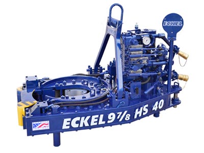
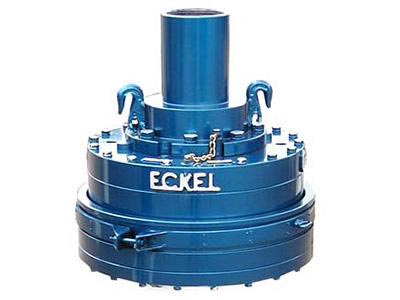
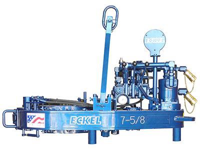
Eckel�s 9⅞ HS-40 Tubing / Casing providing high torque and high continuous rotational torque that you can trust within a compact operational footprint featuring SPACE SAVER® technology.
The 9⅞ HS-40 Tubing / Casing is the result of months of engineering and extensive stress analysis that insures higher performance, reliability, and long life. Eckel 9⅞ HS-40 provides world-class performance with up to 40,000 ft-lbs maximum torque. The tong features our new patented CASE STIFFENER technology that enhances overall torque output. Having a high full 360� rotational torque and speed-shifting capability insures the tong can makeup special torque-turn connections that require continuous rotation. A two-speed Hydra-Shift® motor is coupled with a two-speed gear train to provide (4) torque levels and (4) HS- speeds allowing the operator remarkable control of the connection.
Tong dimensions are a critical design aspect that our engineers worked to reduce for today�s smaller rigs. The result was having one of the industry�s smallest operational footprints tongs for its capacity and torque. The patented SPACE SAVER® door that hydraulically opens vertically, allowing for the tong to work in a much smaller operational area on rig floors and is also less labor-intensive operating. The door opens to the opposite side of the tong operator, allowing full view of the tong throat area while positioning the tong on the tubular. A fast 2-second door operation is all that is required to open or close the door.
The safety door interlock prevents tong operation when the tong door is open. Now enclosed within the tong body, providing tamper-resistant concealment from operator circumvention. Accidental damage of the door interlock by hydraulic fluids, tubular connection, or other external forces is also greatly minimized. A front panel provides access to the door inter-lock for any maintenance required
The 9⅞ HS-40 Casing Tong offers exceptional gripping capabilities handling tubular size from 3½ - 9⅞ in. (88.9 - 250.8) and WD Tri-Grip® Backup size 3½ - 11 in. (88.9 - 279.4). An innovative design allows you to choose either sliding heads or pivot heads configuration upon order. Wrap-Around dies are offered which securely encompass the tubular to limit potential for damage. Therefore, you are assured of your down hole tubular connection integrity.
The present invention relates to open-head power tongs used in drilling operations, and more particularly, is directed to an improved means of actuating and deactuating the operation of the power tong drive means in response to the opened and closed positions of an access door.
As well known in the drilling industry, power tongs are employed in making-up and breaking-out operations of casings, tubings, rods, pipes and the like. More particularly, power tongs are used to grip and rotate lengths of drill pipe or the like to connect or join several lengths of pipe together to thereby form a drill string in a make-up operation, and in the alternative, to grip and rotate a length of drill pipe to disconnect it from the drill string in a break-out operation.
One type of power tong commonly used today is the open-head tong, such as the one shown and described in U.S. Pat. No. 4,060,014. The open-head tong has a bifrucated frame defining a central opening and a side opening communicating with the central opening for the passing therethrough of a drill pipe or the like. Due to the extreme costs of drilling, open-head tongs have become very popular, in that, they can easily and readily be moved into and out of an operative position when they are needed in the making up and breaking out of drill strings.
In operation, the open-head power tong exerts large rotational torques on the drill pipes, usually the larger the tong, the larger the torque output. Due to these large torque outputs and the resulting forces generated therefrom, the open-head tongs have been provided with an access door that bridges the gap between the bifrucated ends of the tong. The primary purpose of such an access door is to strengthen the tong structure so as to prevent, during the operation of the tong, the bifrucated ends from separating or springing apart, which not only results in damage to the tong, but could also inflict injury to the operating personnel. The access door, in addition to providing structural rigidity to the tong, also provides the operator with safety in bodily protecting him from the rotating pipe gripping and engaging jaws.
Such access doors perform very satisfactorily in providing structural rigidity to the tong and do provide protection to the operators from the rotating components of the tong when the door is properly latched in position during the make-up and break-out operations; however, in an effort to save time, operators have been known to operate the tong with the access door open, and in some instances, the operators have even removed the access door from the tong. Such operator"s carelessness not only causes costly structural damage to the tong, but also results in personal injury to the operator.
In U.S. Pat. No. 2,705,614 there is shown an open-head power tong having an automatic hydraulically powered access door, operably interconnected to the hydraulic cylinders that actuate the jaw gripping mechanism, which must be closed before the jaws can be actuated so as to rotate a drill pipe. Such door interlock mechanism has been specifically designed for the type of tong disclosed and is not readily adaptable to other types of power tongs, such as the one shown in the above-mentioned U.S. Pat. No. 4,060,014. Further, the hydraulic circuitry that is involved with such a powered access door is not only complicated, having expensive components, but is also, costly to maintain and repair. Still further, such door interlock mechanism does not provide adequate safety to an operator, in that, although the operator is protected from the pipe gripping and engaging mechanism when the door is closed, he is also subjected to the risk of having the power operated door being automatically swung into him as it is being closed, thus, creating a potentially dangerous and unsafe condition under which the operator must work.
The present invention obviates the problems experienced with access doors and disadvantages associated with the prior art door-interlock mechanisms by providing, as one of its principle objects, an improved door-interlock mechanism for an open-head power tong that ensures the access door is in a closed position before the tong can be operated, thereby preventing possible structural damage to the tong from operating the tong with the door open, as well as, preventing personal injury to the operators by protecting them from the various rotating components of the tong.
Another object of the present invention is to provide a door-interlock mechanism for an open-head power tong that is simple in structure and adaptable to all types of open-head power tongs.
Accordingly, the present invention, sets forth in an open-head power tong having an access door mounted on the tong and moveable between opened and closed positions, an improved door-interlock mechanism that includes means for controlling the operation of the tong in response to the opened and closed position of the door. More particularly, the control means preferably includes a pneumatic contact valve interconnected with a pneumatically piloted diverter valve operably associated with the power means of the tong such that the power means is placed in either an operative or inoperative condition in response to respective closed and opened positions of the door. Specifically, the pneumatic contact valve is so positioned in the vicinity of the side opening that the door, in its closed position, engages the contact valve thereby actuating the diverter valve to permit operation of the power means, and when, the door is moved from its closed position out of engagement with the contact valve, the contact valve causes the diverter valve to deactuate the power means, thus stopping the operation thereof.
FIG. 1 is a top plan view of an open-head power tong incorporating the improved door-interlock mechanism of the present invention with the access door being in its closed position in engagement with the contact valve which actuates the diverter valve.
FIG. 2 is a diagrammatic fragmentary view of the power tong showing the side edge portion of the access door with the door latch removed and with the contact valve being in disengagement with the door which is partly open.
Referring to the drawings, and particularly, to FIG. 1, there is shown, for illustration purposes only, an open-head power tong, being generally indicated by the numeral 10, incorporating the principles of the present invention. The tong illustrated in FIG. 1 is of the type shown and described in U.S. Pat. No. 4,060,014, and thus, for the sake of brevity, since the tong itself forms no part of this invention, only a brief description of the tong will follow.
Briefly, as best seen in FIG. 1, the power tong 10 is comprised of a bifrucated frame structure 12 defining a central drill pipe receiving opening, and a side opening that communicates to the central opening for laterally passing a drill pipe therewithin. Rotatably supported within the frame structure 12 is a pipe engaging and gripping means that includes jaws 14 that swing into and out of the central opening for gripping and rotating a drill pipe disposed within the central opening during make-up and break-out operations of a drill string. The pipe engaging and gripping means with its associated jaws 14 are rotatably driven through a suitable drive train (not shown) by power means such as the hydraulic motor 16 which receives fluid under pressure from a suitable hydraulic pump (not shown) and through a hydraulic control valve 17. The valve 17 is conventional, being moveable between three spool positions; one position being such that the fluid drives the motor in a forward clockwise direction, another position being such that the hydraulic fluid drives the motor in a reverse counterclockwise direction, and the third position being a neutral position wherein fluid passes through the valve to the return line that returns the fluid to a reservoir (not shown) for recirculation thereof.
Also supported on the frame structure 12 is an access door 18, adapted to span or bridge the access opening defined between the bifrucated end portions so as to provide structural rigidity to the power tong 10, as well as, to protect the operator from the various moving components, such as the jaws 14. One end of the access door 18 is hinged to an end of one of the frame bifrucations by a pivot pin 20 whereas the free end of the door is provided with a self-latching arm 22 that engages a latch member 24 mounted on the other bifrucation so as to positively latch the door when it is closed. The door and the door latching mechanism are of the type shown and described in a pending U.S. application, bearing U.S. Ser. No. 791,752; filed Apr. 28, 1977; and entitled TONG LOCKING MECHANISM. The door and the latching mechanism forms no part of this invention and thus a further description will not be given.
To ensure that the tong 10 is only operated when the door 18 is closed, closing the access opening, the tong 10 is provided with an interlock mechanism which basically includes a contact valve 26, engageable by the door 18, and a hydraulic diverter valve 28, operably associated with the hydraulic motor 16 so as to permit flow of hydraulic fluid to the motor, or, in the alternative position, to bypass the flow of hydraulic fluid around the motor.
As seen in FIGS. 1 and 2, in particularly FIG. 2, the contact valve 26 is mounted on the front side of the frame structure 12, in proximity to the access opening, and is so positioned to be engaged by the door 18 when the door is closed and disengaged when the door is opened. The contact valve 26 has an internal spring that biases the valve to its disengaged position. A suitable source for generating pneumatic pressure, such as a compressor (not shown) is provided to supply pressure to the valve 26 through inlet line 30 and therethrough, when valve 26 is in its engaged position, via line 62 to one end of the pneumatic piloted hydraulic diverter valve 28. When pressure is so applied on the diverter valve 28, the valve is so positioned to permit hydraulic fluid to flow to the motor 16 and thereby its operation. However, when pressure is relieved from the diverter valve 28, which is caused when the door 18 is disengaged from the contact valve 26, an internal biasing spring forces the valve to a position which diverts the flow of hydraulic flow around the motor 16, and thus, stoppage thereof.
Now turning to FIG. 3 which schematically represents the various operating components as well as the hydraulic and pneumatic circuitry associated therewith, the operation of the door interlock will be further described. First, it should be noted that both the hydraulic source and the pneumatic source are fully operating with respective fluids being under pressure in inlet lines, the access door 18 being closed, engaged with the actuating arm of the contact valve 26, the piloted diverter valve 28 being detented so as to pass the flow of hydraulic fluid around the motor 16, and with the hydraulic spool control valve 17 being in its neutral position such that fluid passes directly therethrough to the reservoir tank via inlet line 34, passageway 36, return line 38. Thus, as the spool valve 17 is shifted to its forward drive position, hydraulic fluid passes from the inlet line 34, through passageway 40, to line 42, through passageway 44 (of diverter valve 28), to line 46 which directs fluid into the left-hand side of the motor 16, and then via lines 48,49 to passageway 50 of valve 18 which is internally connected to the hydraulic return line 38. If the spool valve 17 is shifted in an opposite direction so as to reverse the direction of the motor 16, fluid flows via line 34, through passageway 52 to line 49 and line 48 to the right side of the motor 16, and then returns via lines 46, passageway 44, line 42 to passageway 54 which is internally connected to return line 38. It can be thus seen that when pressure is applied on the diverter valve 28, it is so positioned to pass hydraulic fluid either to one or the other sides of the motor 16 to thereby drive the rotating components of the tong 10 in either forward or reverse directions depending on the forward or reverse positions of the control valve 17. However, when the pneumatic pressure is relieved from the diverter valve 28, the internal spring forces the valve to the right, thus changing the flow path of the hydraulic fluid so as to bypass the motor 16. In such pressure relief position of the diverter valve 28, the fluid flow path is via lines 49,58, passageway 56 and line 42, thereby bypassing the flow of fluid to the motor 16. Since the flow of fluid through line 46 is blocked, no fluid passes to the motor 16, thus rendering it inoperative.
Thus, it can be readily appreciated from the above, that hydraulic fluid is either directed to the motor 16 for operation thereof, or bypassed therearound, preventing its operation, depending on the position of diverter valve 28. The diverter valve 28 is caused to move between its respective positions in response to the engaged and disengaged positions of the contact valve 26. In its engaged position, air under pressure passes from inlet line 30 through passageway 60 to line 62 for applying pressure to the diverter valve 28 to thereby maintain it in its retracted position wherein hydraulic fluid is permitted to pass to the motor 16. However, when the access door 18 is opened, disengaged from the contact arm of the contact valve 26, the internal spring in the contact valve 26 moves the valve to the left, thereby relieving the pressure in line 62 by venting it to the atmosphere through passageway 64, causing the internal spring to shift the position of the diverter valve 28 such that hydraulic fluid flow is bypassed around the motor 16, thus non-operation thereof.
It can be understood from the foregoing that the described interlock-mechanism controls the operation of the hydraulic motor 16, and thus the operation of the tong 10, in response to the open and closed positions of the access door 18, such that the tong 10 can only be operated with the access door 18 in its closed position, and thereby eliminating the possibility of structural damage to the tong from operating same with the door open, as well as, providing safety to the operator from exposure to the various operating components of the tong.
Tongs - Power - STARR 9-7/8 TONGS 40K AND 60K MODELS AVAILABLE, WITH OR WITHOUT INTEGRAL BACKUP. TOOLS ARE SOLD WITH ONE YEAR WARRANTY. ACCESSORIES ARE AVAILABLE IN STOCK ON REQUEST. C... More Info
This invention is directed to apparatus and methods for aligning wellbore tubulars; and to power tongs used in making and breaking joints of tubular members such as wellbore casing and tubing; to parts thereof; including, but not limited to gripping elements, and methods of their use.
During the drilling of oil and gas wells and the production of materials therefrom, various operations require the connection and disconnection of successive lengths of threaded tubulars such as pipe, casing, or tubing. Tools known as tongs are used to "make" and "break" such connections. Certain known power tongs have a body, a rotary rotatably mounted in said body and at least one active jaw which, on rotation of the rotary is cammed against a pipe in the rotary and grips it for rotation with the rotary. In known arrangements the camming action is generated by a cam member which is bolted to the rotary and is shaped so that the active jaw is cammed against the pipe on rotation of the rotary relative to the active jaw in one sense and will be released on rotation of the rotary relative to the active jaw in the opposite sense.
With known tongs high torques are applied to tubulars due to combinations of factors such as thread sealing requirements, the presence of corrosion, the existence of distortion, and pipe size and weight. Both in the "make" direction of rotation when a shoulder is suddenly encountered, and in the "break" direction at initial engagement of the tong and disengagement of the threads high shock forces may arise; e.g., with a power-driven tong, in excess of 50,000 foot-pounds of torque may be exerted, while relatively small die elements on jaws of the tong engage the pipe with extremely high force loadings. Slippage occurs and pipe surfaces become marred, marked, indented, or otherwise damaged.
Dies for gripping jaws have been provided with multiple serrations, or penetration features, to provide the interference contact at the joint surface. Grip element penetration into the joint surface is limited and controlled. The distribution and balance of grip element energizing forces are critical factors in the design, development and evaluation of such tong mechanisms. Linkages, levers, wedges, and cams are used to balance force components. Grip elements, or dies, are accurately disposed within carrier bodies, or jaws, which span a circumferential segment of the joint surface.
Uneven die loading can cause excessive indentation, marring or damage to a tubular surface. Drag or braking devices are used in certain tongs to effect proper biting of the dies relative to the pipe. The head or other member supporting the dies is frictionally restrained to insure that the dies do not simply rotate with the rotary as the rotary is driven.
Other tongs use an endless belt, chain or flexible material loop for gripping a tubular. Such tongs are disclosed in U.S. Pat. Nos. 3,799,010; 3,906,820; 3,892,140; 4,079,640; 4,099,479; and 4,212,212. There are a variety of problems associated with certain of these tongs:
Jaw/die tongs and the belt/chain tongs are used with relatively hard and rigid metal tubulars such as casing and tubing. If these tongs are used with thick tubulars or tubulars made from relatively "softer" metals or from premium metals such as high alloy steels or low carbon steels or tubulars made from non-metal materials such as fiber glass, they often literally chew up the tubular. The use of strap wrenches is inadequate since the torque applied with such wrenches cannot be precisely controlled.
Certain tubulars are treated with a rust or corrosion resistant material or coating. If the coating is indented, gouged, or broken, its protective purpose is defeated. Producing enough force in a tong to join such tubulars while not injuring a protective coating presents a dilemma.
The present invention, in certain embodiments, discloses a power tong for joining tubulars so that marking of, indentation of, and surface injury to tubulars are reduced or eliminated. In one aspect a power tong is provided and a method of its use for handling tubulars coated with a corrosion-resistant material which should not be broken or penetrated. In one embodiment such a tong has one or more gripping jaws with gripping elements made of aluminum alloys, zinc, zinc alloys, aluminum, brass, bronze, cermet, plastic, fiberglass, metal alloys, or a combination thereof which present a smooth face (straight or curved) to a tubular without any teeth, pointed projections, or toothed dies. In one aspect the gripping elements are releasably connected directly to jaws. In another aspect the gripping elements are releasably connected to a jacket or holder which itself is releasably connected to a jaw.
In one aspect the cylinder(s) are powered by a small air-driven hydraulic pump with an hydraulic fluid reservoir mounted on a plate on the movable or fixed jaw. Air is supplied to activate a motor of the pump and the pump then provides hydraulic fluid to move a piston of the hydraulic cylinder(s). The motion of the cylinder moves the movable jaw on its roller to travel to a pre-load position on the cam. The cylinder applies pressure until the hydraulic pressure is released. A hydraulic fluid accumulator and a valve may be used to maintain hydraulic pressure at all times so that the cylinder(s) continuously maintain the desired load on the jaw until the air supply to the pump is removed.
In another aspect the cylinders are connected to a rotary of the tong or to any other member that rotates with the rotary rather than to a fixed jaw. Such a pre-load system may, according to this invention, be used with any tong including a tong that does use toothed dies.
In one embodiment the present invention discloses a gripping arrangement for a tong with a sheet of grit which is preferably bonded to a carrier plate. In another embodiment the gripping arrangement comprises a layer of flexible material having a smooth flat surface or a surface with ridges and valleys, for example in the fashion of the surface of a file. The flexible material, in one aspect, is metal, for example sheet aluminum, zinc, brass, bronze, zinc alloy, aluminum alloy, stainless steel, or steel having a thickness of about 1.5 mm. The layer of flexible material may be used in conjunction with a carrier plate or on its own. In a further embodiment the gripping arrangement may comprise a layer of perforate material one of both surfaces of which are preferably coated with grit to facilitate adhesion. The layer will typically be formed from metal having a thickness of about 1.5 mm. The layer may be used in conjunction with a carrier plate or used on its own. In yet another embodiment the gripping arrangement may comprise a layer of expanded mesh, e.g. metal mesh, which has been flattened. One or both surfaces of the expanded mesh may be coated with grit and the layer may be used in conjunction with a carrier plate or used on its own. The grit may comprise, for example, diamond dust, particles of silicon, zircon, tungsten carbide and mixtures thereof. The gripping arrangement may comprise end plates which are attached to the carrier plate. Preferably, the carrier plate is provided with side flanges for insertion into a jaw holder. The present invention also provides a jaw assembly fitted with a gripping arrangement in accordance with the present invention. Preferably, the jaw assembly includes a jaw holder having an arcuate recess which accommodates an arcuate pad of resilient elastomeric material which supports said gripping arrangement. Advantageously, at least one shim is provided which is disposed between said arcuate pad of resilient elastomeric material and said gripping arrangement. The shim will be flexible and generally from 0.5 mm to 1.0 mm thick and made from sheet metal. The present invention also provides a tong fitted with at least two such jaw.
In one embodiment the present invention discloses an apparatus for aligning tubulars and includes a guide on one of a power tong and a backup tong. In one embodiment the apparatus has a socket centralizer mounted on said one of said power tong and said backup tong. In one aspect, said one of said power tong and said backup tong is said power tong. In another embodiment, the apparatus includes a power tong and a backup tong, and the guide is mounted on the power tong and apparatus is provided to maintain the power tong and the backup tong in a certain juxtaposition during a stabbing operation. Preferably, said apparatus includes locating rods on one of the power tong and the backup tong and blocks shaped to receive at least the ends of the locating rods on the other of the power tong and the backup tong. Advantageously, the backup tong is provided with at least two prismatic jaw assemblies to locate the backup tong in fixed juxtaposition with respect to a tubular being gripped.
The present invention, in one aspect, provides a jaw unit for use in a tong, which jaw unit comprises a jaw holder and a jaw movable with respect to said jaw holder, characterized in that said jaw is slidably mounted on said jaw holder. Preferably, said jaw is slidable with respect to said jaw holder about an arcuate path. Advantageously, said jaw has a gripping surface which is substantially arcuate for gripping the surface of a tubular and the center of curvature of such arcuate path lies between the center of curvature of said grip ping surface and said arcuate path. The gripping surface may be a continuous surface or defined by several spaced apart gripping elements. Preferably, the center of curvature of said arcuate path lies between the center of curvature of said grip ping surface and said gripping surface. Advantageously, the center of curvature of said arcuate path is substantially midway between the center of curvature of said gripping surface and said gripping surface. Preferably, one of said jaw and said jaw holder is provided with an arcuate track which defines said arcuate path, and the other of said jaw and said jaw holder is slidably mounted in said arcuate track.
The present invention also provides a jaw assembly comprising two jaw units in accordance with the present invention. Preferably, said jaw units are mounted for pivotal movement about a common pivot shaft. Advantageously, said jaw assembly includes means which bias said jaw units apart. The present invention also provides a rotary fitted with a jaw unit in accordance with the present invention, a rotary fitted with a jaw assembly in accordance with the present invention, and a tong fitted with a rotary in accordance with the present invention.
One of the features of existing tongs is that their rotaries are difficult to furnish. Thus, routine maintenance usually involves dismantling the whole rotary, checking the parts and reassembling the whole. While this is a straightforward procedure in the clean conditions of a workshop it can be problematic when carried out in a muddy field, in sand or in snow. The present invention aims to help solve this problem and provides a rotary which comprises a top section, a bottom section, and a peripheral wall therebetween, characterized in that at least one of said top section and said bottom section is provided with an elongate slot which, when said rotary is in use, accommodates a pivot shaft on which a jaw assembly can be pivotally mounted.
Jaw holders and jaws for tongs are traditionally machined from a solid piece. This is a comparatively expensive procedure. The present invention proposes to make such parts from a stack of individually cut laminations.
Such methods and devices including a power tong with at least one jaw with at least one tubular gripping element having a smooth gripping surface (flat or curved) and, in one aspect, such an element which is flexible;
FIG. 2A is a perspective view of a tubular connection system according to the present invention. FIGS. 2B and 2C are perspective views of a casing tong of the system of FIG. 2A.
FIG. 5A shows schematically an initial position of elements of a tong system according to the present invention. FIG. 5B shows pre-loading on a pipe of the jaws of the system of FIG. 5A. FIG. 5C shows a tubular gripped with the system of FIG. 5A.
FIGS. 1A-1C show a typical prior art power tong that uses fixed jaws and a movable jaw to grip pipe for tubular disconnecting and connecting operations. An outer case houses a powered rotary to which the jaws are mounted. A cam surface of the rotary moves a movable (ACTIVE or MASTER) jaw into (and away from) gripping contact with a tubular, e.g. pipe. Each jaw has toothed gripping inserts to facilitate engagement with the surface of the tubular (see FIG. 1B). FIG. 1C shows the tong in an "OPEN" position in which the tubular is not gripped.
The tong shown in FIG. 1A is a Weatherford Model 14.5-50 High Torque Tong. The brochure "New ! Weatherford Model 14.5-50 High Torque Tong," (1991) and the manual entitled "Model 14.5-50 Hydraulic Power Tong Installation, Operation and Maintenance" (1993) are submitted herewith and incorporated herein fully by reference for all purposes. It is to be understood that the teachings of the present invention are applicable to any tong and any tong system that has one or more gripping elements or jaws and that the Model 14.5-50 tong is shown here for illustrative purposes and not by way of limitation of the scope of the present invention.
As shown in FIG. 2A a system 10 according to the present invention includes a power tong 100 according to the present invention which is like the tong of FIG. 1A but which also includes a unique jaw system 110 with inserts 150 on fixed jaws 120 and insert 152 on movable jaw 122 and at least one jaw pre-load assembly like that shown in FIG. 5A. The system 10 includes a free floating backup tong 12.
As shown in FIGS. 2B and 2C, rods 112 are connected to the movable jaw 122. The inserts 150 are on fixed jaws 120 and the insert 152 is on a movable jaw 122 (corresponding to the fixed jaws and active jaw, respectively, of the tong of FIG. 1A).
FIGS. 4A-4G illustrate an alternative jaw mounting system in which holders are interposed between jaw bodies and inserts. The holders protect the jaws from damage if the inserts wear down and a variety of different types and/or sizes of inserts may be used with and interchanged on a single holder. In one aspect it is within the scope of this invention to use these holders to mount conventional toothed dies to a tong jaw and to use them for easy substitution of new and/or different dies.
FIG. 4A shows a jaw system 400 for a tong (like the tong of FIG. 2A) which has two fixed jaws 402 and a movable (movable toward and away from a tubular to be gripped 403) jaw 404. Each jaw 402 has a jaw body 405 with a holder 406 secured thereto. In one aspect dovetail keys 407 secured to the holder or releasably mounted thereto fit in corresponding slots 408 of the jaw bodies 405 to releasably mount the holder 406 to the body. In one aspect dovetail keys 409 releasably mount the holders 406 to jaw bodies 405. The dovetail keys 409 are releasably held in corresponding recesses 411 in the holders 406. One or more dovetail keys 409 may be used (two shown for each holder 406).
It is preferred that the insert 420 extend for an arc of at least 40 degrees and most preferably at least about 90 degrees. It is preferred that each insert 410 extend for an arc of at least 20 degrees and most preferably at least about 60 degrees. In another aspect it is preferred that the combined arcs of the three inserts in FIG. 4A extend for at least 180° of the total 360 degree circumference of the tubular 403 and most preferably for at least 20 degrees.
FIG. 5A shows a tong system 500 with a tong having a movable rotary 502, fixed jaws 504, 505, and a movable jaw 506 (remainder of tong, not shown, like the tong of FIG. 2A; like the tong of FIG. 1A, but with the added features discussed here). Pins 520 pin the fixed jaws to the rotary. Inserts 522 on the fixed jaws 504, 505 are like the inserts described herein for other fixed jaws. Insert 524 on the movable jaw 506 is like other inserts described herein for movable jaws. A pre-load cylinder 508 to assist in make-up is pivotably connected at one end to the fixed jaw 505 and at the other end to the movable jaw 506. A pre-load cylinder 510 to assist in break-out is pivotably connected at one end to the fixed jaw 504 and at the other end to the movable jaw 506. It is within the scope of this invention for the ends of cylinders connected to the fixed jaws to instead be secured to the rotary or to a support ring or other member that rotates with the rotary. It is within the scope of this invention to employ one cylinder interchangeable between the positions of the cylinders 508 and 510 (FIG. 5A) or one cylinder connectible to the fixed jaw 506 at one end for break-out and at the other end of the fixed jaw 506 for make-up with the other cylinder end secured to the rotary. Rollers 530 rotatably mounted on the movable jaw 506 co-act with cam surfaces 532 on the rotary 502 to move the jaw 506 to operative and inoperative positions.
The system 600 has a directional control valve 602 that directs fluid from a reservoir 608 in lines 604, 606 to one or both cylinders or from one or both cylinders. An accumulator 610 holds sufficient hydraulic fluid under pressure to maintain desired continuous pressure levels on the pre-load cylinders so that the cylinders maintain the desired pre-load force without interruption or decay due to fluid bleed-off.
A bleed valve 620 functions to selectively release pressure from the pre-load cylinders following make-up or break-out. A pump 630 pumps hydraulic fluid from the reservoir 608 to a line 631, in a line 632 to the accumulator 610, in a line 633 to the directional control valve 602, and in lines 634 and 635 to (and from) the pre-load cylinders 508 and 510. A check valve 638 in a line 637 from the reservoir 608 prevents fluid from flowing back into the reservoir. A check valve 639 in the line 631 insures that the pump 630 pumps fluid only from the reservoir and prevents fluid from the cylinder 508, 510 and/or from the accumulator 610 from flowing back to the pump 630 and to the reservoir 608.
Air in a line 640 selectively applied with a control system 650 (e.g. mounted on the rig floor, on the tong or remote controlled) selectively actuates the pump 630 to pump fluid through the valve 602 to the pre-load cylinders. The directional control valve 602 is either manually operated or operated by remote control. Correct fluid pressure is monitored with a gauge 651.
As shown in FIG. 5C the tubular 650 has been gripped due to the action of the pre-load cylinder 510 with a suitable pre-load force (e.g., but not limited to, about 500, 1000, 5000, 10000 or 50000 pounds of force). This force is sufficient that when the rotary 502 of the tong is rotated the jaws do not slip on the tubular 650; but the pre-load force is sufficiently low that the jaws do not mark or damage the tubular 650.
FIG. 8 shows schematically a top view of a power tong according to the present invention. A power tong T has an hydraulic motor M with control/monitor apparatus C on a tong case S. A movable jaw J is moved and rotated by a rotary R which is moved by interconnection, via appropriate gearing, by the motor M. Fixed jaws F and G are secured to the rotary R. A first pre-load cylinder D connects the movable jaw J to the fixed jaw G for applying a pre-load to the movable jaw for make-up operations. A second pre-load cylinder L connects the movable jaw J to the fixed jaw F for applying a pre-load to the movable jaw for break-out operations. An insert I (any insert disclosed herein) is secured to the movable jaw J and inserts K (any insert disclosed herein) are secured to the fixed jaws F and G.
FIG. 9 shows a tong jaw 450 according to the present invention with an insert 454 (any insert disclosed herein) and rods 452 secured thereto, e.g. by welding. The rods 452 provide a member to which either a cylinder body or a piston of a pre-load piston cylinder apparatus is connectible. Instead of the rods 452 as shown which extend from above the jaw 450 to a point below it, only rod sections may be used secured to one or both sides of the jaw to provide a securement member for an end of a pre-load apparatus.
According to the present invention a variety of apparatuses and devices may be employed to pre-load a tong jaw having one or more smooth faced gripping insert elements thereon. In one aspect a manually activated pre-load cylinder is used which has fluid or material manually introduced therein to apply a pre-load or manually removed therefrom to release a pre-load. In another aspect a pre-load cylinder is pivotably secured at one end to a rotary or part thereof and the other end is releasably connectible to either end of a movable jaw so that a pre-load may be applied, selectively, to either end of the movable jaw for make-up or break-out operations as desired. In one aspect such a pre-load cylinder has a rod with an end member receivable in and movable in a slot in the movable jaw or there are recesses at either end of the jaw for holding the end member of the rod so that a pre-load can be applied. A secondary small cylinder may be used to selectively move the pre-load cylinder in the jaw slot or it can be moved manually. In another embodiment the tong"s movable jaw has one or more upwardly projecting lugs engageable by a forked piston rod end of a pre-load piston/cylinder that is attached to the rotary. The rotary is rotated so that the jaw is cammed into the pipe to be rotated in a pre-load position and then the forked rod is removed for further tong operations.
In use, two or more jaw assemblies are placed in a tong and are disposed around a length of casing. The jaw assemblies 1001, 1001" are then advanced radially inwardly in the direction of arrows "A" (FIG. 12) until they engage and firmly grip the casing. Because of the flexible construction of the gripping arrangement 1007, the shims 1006 and the arcuate pad 1004, the friction layer 1009 substantially conforms to the circumference of the casing and grips the casing with a substantially uniform gripping action. Once the casing has been firmly gripped the jaws are rotated by the tong in the usual manner. It will be noted that circumferential forces applied to the friction layer are transmitted through the carrier plate 1008 so that any local loads caused, for example by an irregularity in the surface of the casing are redistributed by the carrier plate 1008 and transmitted to the jaw holder 1002 via the side flange 1011 and the arcuate pad 1004 (see FIG. 18).
Referring to FIGS. 19A and 19B of the drawings there is shown a conventional tong assembly which is generally identified by the reference numeral 2001.
The power tong 2002 comprises a pair of gates 2004, 2005 which are held together in the position shown by latch 2006. When the latch 2006 is released the gates 2004, 2005 can be swung open by admitting hydraulic fluid to piston and cylinder assemblies 2007 and 2008. The power tong 2002 also contains a rotary 2009 which is provided with four jaw assemblies 2010. The rotary 2009 can be rotated by a hydraulic motor 2011.
The backup tong 2003 is provided with two gates 2012, 2013 which are held together by latch 2014 but which, when latch 2014 is released can be swung to an open position.
Once the pin is correctly located the stabbing guide is removed. The gates 2004, 2005 of the power tong 2002 and the gates 2012, 2013 of the backup tong 3 are then opened and the tong assembly 2001 moved towards the casing until the lower length of casing lies within the backup tong 2003 and the upper length of casing lies within the power tong 2002. The gates 2004, 2005, 2012, 2013 are then closed and latched. Jaw assemblies in the backup tong are then advanced to engage the lower length of casing while jaw assemblies in the power tong 2002 are advanced to grip the upper length of casing. The hydraulic motor 2011 is then actuated to turn the rotary 2009 and rotate the upper length of casing relative to the lower length of casing. The tong assembly 2001 is supported by a pneumatic lifting cylinder 2015 which enables the power tong 2002 to move towards the backup tong 2003 as the pin enters the socket. Reaction forces are transmitted by columns 2016 disposed to either side of the tong assembly 2001 and by a series of levers in a known manner. It should be noted that the power tong 2002 is free to move in a plane parallel to the backup tong 2003 within certain limits.
The apparatus 2100 comprises a tong assembly 2101 which is generally similar to the tong assembly 2001 shown in FIGS. 19A and 19B and parts of the tong assembly 2101 similar to the tong assembly 2001 have been identified by similar reference numerals in the "2100" series.
Turning first to the guide 2117 it will be seen from FIG. 21B that this comprises four identical components 2118 which are bolted to the top of the power tong 2102. As best shown in FIG. 21C each component is tapered so as to guide the pin of an upper casing to the center of the opening of the power tong 2102.
Referring now to FIG. 22, the backup tong 2103 is provided with three prismatic jaw assemblies 2119a, 2119b, and 2119c which, when actuated, hold a lower length of casing 2120 in a fixed position relative to the backup tong 2103.
As shown in FIG. 23 the backup tong 2103 is provided with three upwardly extending locating rods 2121 which are each provided with a conical tip 2122. Similar, the underside of the power tong 2102 is provided with three blocks 2123 each of which is provided with a recess 2124 shaped to receive the conical tip 2122 of a respective locating rod 2121.
In use, the lower length of casing 2120 is first secured by slips on the rig floor in the usual manner. The gates 2112 and 2113 of the backup tong 2103 are then opened and the tong assembly 2101 moved into position with the backup tong 2103 circumjacent the lower length of casing 2120 and immediately below the socket 2125 thereof.
The gates 2112 and 2113 are then closed by hydraulic piston and cylinder assemblies 2126 and 2127 and the latch 2114 closed. The prismatic jaw assembly 2119a is fixed while prismatic jaw assemblies 2119b and 2119c are automatically advanced by a predetermined distance when the latch 2114 is closed. This grips the lower length of casing firmly and also ensures that the backup tong 2003 is in a fixed position relative to the lower length of casing 2120. The position thus far attained is shown in FIG. 23.
At this time pneumatic lifting cylinder 2115 is extended which lowers the backup tong 2003. The conical tips 2122 of the locating rods 2121 enter the recesses 2124 of the blocks 2123 and thus locate the power tong 2002 with respect to the backup tong 2003. This in turn locates the guide 2117 with respect to the lower length of casing 2120 so that the center of the guide 2117 is coaxial with the axis of the lower length of casing 2120. This position is shown in FIG. 24.
The power tong 2102 is then raised so that the blocks 2123 are well clear of the locating rods 2121. At this point the jaw assemblies in the power tong 2102 are applied to the upper length of casing 2128 and the hydraulic motor 2111 actuated to rotate the rotary and screw the pin 2129 into the socket 2125. During the procedure the power tong 2102 moves towards the backup tong 2103. However, even when the joint is tightened to the required torque the blocks 2123 still lie a short distance above the conical tips 2122 of the locating rods 2121.
At this stage the jaw assemblies of both the power tong 2102 and the backup tong 2103 are relaxed, the gates 2104, 2105, 2112 and 2113 opened and the tong assembly 2101 retracted in preparation for the casing being lowered. It will be noted that one component 2118 of the guide 2117 is mounted on each of the gates 2104, 2105 and accordingly the guide 2117 opens and closes with the gates 2104, 2105.
For certain applications a backup tong is not required, for example where the power tong can conveniently be restrained by a chain attached to the drilling tower.
The apparatus 2200 comprises a power tong 2202 which is generally similar to the power tong 2002. The basic construction of the power tong 2202 is similar to the power tong 2002 and parts having similar functions have been identified by the same reference numeral in the "2200" series.
The main differences are that the apparatus 2200 does not include a backup tong and that it is provided with a guide 2217 and a socket centralizer 2230.
In use, the lower length of casing 2220 is first secured by slips (not shown) with the socket 2225 facing upwardly close to the slips. The power tong 2202 is then lowered onto the socket 2225 so that the socket 2225 enters the socket centralizer 2230 and aligns the socket centralizer 2230, the socket 2225 and the guide 2217. The upper length of casing 2228 is then lowered so that its pin 2229 enters the guide 2217, is center there by and enters the socket 2225. At this point power tong 2202 is raised. Its jaw assemblies are then advanced to grip the upper length of casing 2228 which is then rotated to screw the pin 2229 into the socket 2225. Once the joint is tightened to the required torque the gates 2204, 2205 are opened and the power tong 2202 withdrawn.
The embodiment shown in FIG. 29 is generally similar to that shown in FIG. 28 except that the apparatus 2300 also includes a backup tong 2303. Since the upper length of casing 2328 and the lower length of casing 2320 are being aligned by the guide 2317 and the socket centralizer 2330 no special arrangements need be made for aligning the power tong 2302 and the backup tong 2303.
The procedure for connecting the upper length of casing 2328 to the lower length of casing 2320 is as follows. First, the lower length of casing 2320 is secured in slip (not shown). The gates 2312, 2313 of the backup tong are then opened and the apparatus 2300 maneuvered so that the lower length of casing 2320 is disposed within the backup tong 2303. The power tong 2302 is then lowered until the socket 2325 on the lower length of casing 2320 is received within the socket centralizer 2330. The upper length of casing 2328 is then lowered until the pin 2329 passes through guide 2317 and enters the socket 2328. Only at this stage are gates 2312, 2313 closed and the jaw assemblies of the backup tong 2303 activated to grip the lower length of casing 2320. The power tong 2302 is then raised and its jaw assemblies activated to grip the upper length of casing 2328 which is then rotated to cause the pin 2329 to enter the socket 2325 and the joint to be tightened to the desired torque. The jaw assemblies are then relaxed and the gates 2304, 2305, 2312, 2313 of the power tong 2302 and the backup tong 2303 opened prior to retracting the apparatus 2300.
Various modifications to the embodiments described are envisaged, for example, if desired, the guide and the socket centralizer could be mounted on the backup tong 2303 rather than the power tong 2302. Alternatively, the guide could be mounted on the backup tong without a socket centralizer. Such an arrangement is shown in FIG. 30.
The embodiment shown in FIG. 30 is generally similar to that shown in FIG. 19a and 19b and parts of the tong assembly 2401 similar to the tong assembly 2001 have been identified by similar reference numerals in the "2400" series. One difference is that the top of the backup tong 2403 is provided with a guide 2417.
In use, the lower length of casing 2420 is first secured by stops 2431 on the rig floor in the usual manner. The gates 2412 and 2413 of the backup tong 2403 are then opened. Since two of the four components 2418 of the guide 2417 are mounted on the gates 2412 and 2413 the guide 2417 opens with the gates 2412 and 2413 so that the lower length of casing 2420 can enter the backup tong 2403 when the carriage 2432 which supports the apparatus 2400 is advanced towards the casing 2420 on rails 2433. When the lower length of casing 2420 is fully within the backup tong 2403 the gates 2412 and 2413 are closed. The components 2418 of the guide 2417 have a stepped interior (not visible in FIG. 30) so that the lower part of each component 2418 touches the socket on the top of the lower length of casing 2420 whilst the upper part of the interior of each component 2418 tapers inwardly to form a funnel. Once the lower length of casing 2420 has been gripped the upper length of casing 2428 is lowered through the power tong 2402 towards the lower length of casing 2420. The guide 2417 guides the pin on the bottom of the upper length of casing 2428 into the socket. The power tong 2402 is disposed a small distance above the guide 2417. Once the pin of the upper length of casing 2428 has entered the socket on the lower length of casing the jaws of the power tong 2402 are applied to the upper length of casing 2428 which is rotated until the joint reaches the desired torque.
Referring now to FIG. 38, the rotary 3100 is shown fitted in a tong 3116. As shown in FIG. 39 and 40, the rotary 3100 is formed as a one piece casting which comprises a top section 3117, a bottom section 3118, and a peripheral wall 3119 on which is formed a toothed track 3120. Both the top section 3117 and the bottom section 3118 are provided with an elongate slot 3121, 3122 respectively. Each elongate slot 3121, 3122 has its center of curvature on the center of rotation of the rotary 3100.
As can be seen in FIG. 38 and FIGS. 31 to 37, the sides of the rotary 3100 are provided with cams 3128, 3129, 3130 and 3131 which are screwed to the rotary 3100. The rotary 3100 is located in the tong 3116 by nine guide rolls 3132, five of which are visible in FIG. 38. The guide rolls 3132 each have an upper and a lower roller which bears against the peripheral wall 3119 of the rotary 3100 above and below the toothed track 3120 respectively.
In FIG. 38 the tubular 3111 is about to be gripped. (This corresponds to the position shown in FIG. 34.) The hydraulic motor (not shown) is actuated to rotate gear wheels 3133, 3134 and 3135 which in turn rotate the rotary 3100 in a clockwise direction. However, while the rotary 3100 rotates the disk 3123 is restrained by the friction member 3125. The disk 3123 in turn restrains the pivot shaft 3103 and the jaw assembly 3101. Because the jaw assembly 3101 is restrained the jaw units 3102 ride up on the cams 3128, 3130 which urge the jaws 3106 into the tubular 3111 until either the pivot shaft 3103 engages the end of the elongate slot 3121 (or the forces between the tubular 3111, the jaw units 3102 and the cams 3128, 3130 are sufficiently high) at which time the disk 3123 rotates in unison with the rotary 3100 against the friction member 3125. It will be noted that because the centers of curvature of the gripping elements 3107 and the arcuate track 3108 do not coincide the jaw holders 3105 do not spin around the jaws 3106 although means to limit the sliding movement of the jaws 3102 relative to their jaw holders 3105 could be provided if desired.
When the tubular 3111 has been tightened to the desired torque the hydraulic motor is reversed to rotate the rotary 3100 anti-clockwise. The jaws 3106 are normally firmly engaged in the tubular 3111 and hence the rotary 3100 rotates relative to the jaw assembly 3101 so that the jaw holder 3105 returns to the position shown in FIG. 38. Means may be provided to prevent the jaw holders 3105 engaging the cams 3129 and 3131.
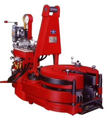
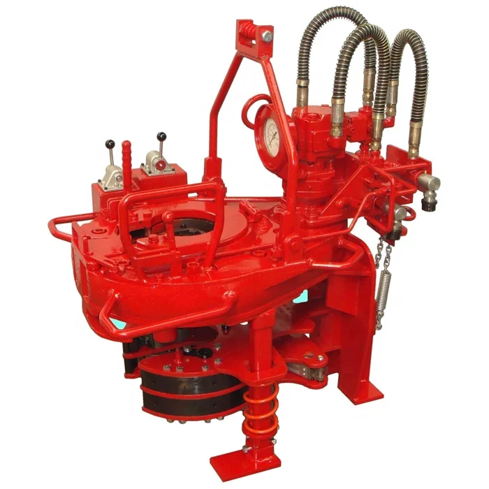
Quality tongs improve the efficiency and safety of drill floor operations. These large-capacity, self-locking wrenches apply torque where needed when making up or breaking out tubing. Just like a plumber using opposing pipe wrenches, rig tongs are always used in opposing pairs. One set of tongs is tied off with a cable or chain to the derrick, and the other is pulled with mechanical catheads.
Tongs used during makeup (tightening) operations are called makeup tongs; the ones used during breakout (the process of unscrewing drill string components) are called breakout tongs. Depending on the specific application, there are also riser tongs, chisel tongs, rotary tongs and manual tongs.
During makeup operations, the “lead tongs” (pronounced “leed”) are the pipe tongs suspended in the derrick or mast and operated by a chain or a wire rope connected to the makeup cathead or the breakout cathead.
The tong pull line is a length of wire rope with one end connected to the end of the tongs and the other to the cathead on the drawworks. When the driller actuates the cathead, it takes in the tong line and exerts force on the tong to either make up or break out drill pipe.
The lead-tong hand is the crew member operating the lead tongs when drill pipe and drill collars are being handled and pipe is going into the hole. For breakout operations, breakout tongs are used to start unscrew sections of pipe from one another, primarily drill pipe coming out of the hole.
Tong dies play a key part in helping power tongs or manual tongs grip tool joints. Running in or pulling out tubular at oil rigs, the tool joints are adjusted with power tongs or manual tongs.
Dies are pieces of serrated steel installed in the tongs that grip the tool joint of drill pipe when the tongs are latched onto the pipe. Tong dies are made of alloy steel, and their hardened surfaces resist wear. The inner ductile core minimizes the shock of impact and torque.
During makeup, how much force should be applied to the tongs to get the torque needed? The formula to determine torque value when you use the rig tong to make-up the connection is this:
Keystone’s K-Series tubing tongs are pull-tested and complete documentation is available with each purchase. Designed for heavy-duty service of tubing 1.050 to 3.875-inch OD, they offer a wraparound design with approximately a 300-degree die contact to prevent crushing of thin wall tubing.
A power tong positioner comprises a vertically movable pedestal with a horizontally disposed sliding carriage mounted atop it, and a ring and pinion gear assembly to rotate the carriage in a horizontal plane. Preferably, the carriage has rollers to ease back-and-forth horizontal movement, under the influence of hydraulic cylinders. A twin-armed lift assembly is pivotally mounted on the roller carriage, and a pair of hydraulic cylinders attached between the roller carriage and the lift assembly pivots the frame on the carriage. The power tong hangs from the lift assembly. The power tong may be positioned at a desired location by a combination of movement of the pedestal, the sliding carriage, and the pivoting lift assembly. Controls for the positioner and the power tong may be mounted on the front of the tong, at a remote control panel connected by an umbilical, or a remote radio frequency signal control panel.
This invention relates to apparatus used in connection with the drilling and servicing of earthen boreholes, commonly called “wells,” and more particularly to apparatus used to position power tongs at desired locations to make up and break out threaded connections on tubular goods. [0002]
Power tongs have come into widespread use in the oil and gas industry, especially on drilling rigs in recent times, to make up and break out threaded connections on tubular goods, referred to herein as tubulars. Tubulars include all manner of threaded connection goods such as tubing, casing, and drill pipe. In particular, the use of power tongs to make up and break out drill pipe threaded connections, commonly called tool joints, has greatly increased. Such connections require high torque values, and consequently the tong units required to generate such torque values are quite heavy. [0004]
The great weight of these power tongs, and increased emphasis on safety and efficiency in rig operations has resulted in a move away from one of the earliest forms of tong “positioners”—that being the tong hung on a line, which is routed over a pulley mounted high in the rig derrick, to a counterweight that suspends the tong above the rig floor, yet permits it to be swung into position and raised and lowered. This form of “positioner” does not restrain the tong from swinging around and striking personnel and other equipment, and otherwise has limitations on its use. [0005]
In response, various types of powered positioners, particularly for positioning power tongs, have been invented to positively position such tongs at desired positions with respect to the rig floor, and more particularly to position the tong around the threaded connection to be made up and broken out. A typical situation is the makeup or breakout of a drill pipe connection, where the tool joint is in the rotary table (essentially in the center of the rig floor) several feet above the rig floor. However, the power positioner must also be capable of placing the tong in positions away from the center of the rig floor, for example to handle drill pipe connections in the so-called rat hole or mousehole, which are displaced from the center of the rig floor. The power positioner must preferably be in a relatively out of the way position on the rig floor, and must position the power tong out of the way when not needed. [0006]
There exist other technologies to position tongs, including boom-type positioners and those which run on stationary tracks typically disposed on the rig floor. The invention of the present application affords another solution to the problem. [0007] SUMMARY OF A PRESENTLY PREFERRED EMBODIMENT OF THE INVENTION
The present invention, in one presently preferred embodiment, is a power positioner for placement of tongs in a desired location about a rig floor. The term “tongs” as used herein comprises any type of powered device with which to makeup and/or breakout threaded tubular connections, whether it be a “make and break” device, conventional power tong, power tong unit comprising a backup, etc. The invention comprises a vertically movable pedestal having a base and a sliding carriage mounted on it. The sliding carriage preferably rides on a plurality of rollers disposed between the base and the carriage, and is movable back and forth horizontally by a pair of hydraulic cylinders. The base is rotationally mounted on the pedestal, such that rotation of the base in turn rotates the carriage in a substantially horizontal plane. A powered pinion and ring gear assembly provides the rotary movement between the base and the pedestal. A lift assembly is mounted on the carriage, and in the preferred embodiment comprises two arms pivotally mounted on the sliding carriage, with a rotating gambrel joining the two arms. A power tong may be suspended from the gambrel. Hydraulic cylinders attached between the lift assembly and the sliding carriage permit pivoting the lift assembly about its pivot points, so that a power tong hanging therefrom is both raised/lowered and moved backward/forward by the pivoting motion. Controls are operationally connected to the power positioner, via any combination of mounting on the tong, at a remote location connected by a control umbilical, or via radio frequency connection, to raise and lower the pedestal; rotate the base on the pedestal; pivot the lift assembly; and move the sliding carriage backward and forward, thereby permitting a power tong to be positioned at a desired location with respect to the rig floor.[0008]
FIG. 1 is a perspective view of a typical rig floor setting showing the apparatus in a fully retracted position, with the power tong in a stored position. [0009]
FIG. 2 is an exploded view of the apparatus in a perspective view of the apparatus in an extended position, with the power tong positioned to engage a drill pipe connection. [0010]
It is understood that the term “power tong,” as used in this application, encompasses any form of powered device used to make up and/or break out threaded tubular connections (on any type of tubular, including drill pipe, tubing, casing, etc.), and includes drill pipe tongs, casing tongs, “make/break” devices, etc. It is further understood that the invention may have application in many different settings; as a matter of convenience only, the invention is described in connection with its deployment on a drilling or workover rig. However, it is equally applicable to positioning tongs in a shop environment, for example. [0014]
FIG. 1 best serves to illustrate a typical installation of the power positioner on a rig floor, in proximity to a threaded tubular connection to be made up or broken out, such as a drill pipe connection. While the power positioner


 8613371530291