
hydraulic power tong api xq28 us patent price

This website is using a security service to protect itself from online attacks. The action you just performed triggered the security solution. There are several actions that could trigger this block including submitting a certain word or phrase, a SQL command or malformed data.
This website is using a security service to protect itself from online attacks. The action you just performed triggered the security solution. There are several actions that could trigger this block including submitting a certain word or phrase, a SQL command or malformed data.

API 7K 2 3/8 2 7/8 3 1/2 Tubing Hydraulic power tong API 7K 2 3/8 2 7/8 3 1/2 Tubing Hydraulic power tong API 7K 2 3/8 2 7/8 3 1/2 Tubing Hydraulic power tong API 7K 2 3/8 2 7/8 3 1/2 Tubing Hydraulic power tong API 7K 2 3/8 2 7/8 3 1/2 Tubing Hydraulic power tong API 7K 2 3/8 2 7/8 3 1/2 Tubing Hydraulic power tong API 7K 2 3/8 2 7/8 3 1/2 Tubing Hydraulic power tong API 7K 2 3/8 2 7/8 3 1/2 Tubing Hydraulic power tongAPI 7K 2 3/8 2 7/8 3 1/2 Tubing Hydraulic power tongAPI 7K 2 3/8 2 7/8 3 1/2 Tubing Hydraulic power tong API 7K 2 3/8 2 7/8 3 1/2 Tubing Hydraulic power tongAPI 7K 2 3/8 2 7/8 3 1/2 Tubing Hydraulic power tongAPI 7K 2 3/8 2 7/8 3 1/2 Tubing Hydraulic power tong API 7K 2 3/8 2 7/8 3 1/2 Tubing Hydraulic power tongAPI 7K 2 3/8 2 7/8 3 1/2 Tubing Hydraulic power tongAPI 7K 2 3/8 2 7/8 3 1/2 Tubing Hydraulic power tong API 7K 2 3/8 2 7/8 3 1/2 Tubing Hydraulic power tongAPI 7K 2 3/8 2 7/8 3 1/2 Tubing Hydraulic power tongAPI 7K 2 3/8 2 7/8 3 1/2 Tubing Hydraulic power tongAPI 7K 2 3/8 2 7/8 3 1/2 Tubing Hydraulic power tong API 7K 2 3/8 2 7/8 3 1/2 Tubing Hydraulic power tongAPI 7K 2 3/8 2 7/8 3 1/2 Tubing Hydraulic power tong API 7K 2 3/8 2 7/8 3 1/2 Tubing Hydraulic power tongAPI 7K 2 3/8 2 7/8 3 1/2 Tubing Hydraulic power tongAPI 7K 2 3/8 2 7/8 3 1/2 Tubing Hydraulic power tongAPI 7K 2 3/8 2 7/8 3 1/2 Tubing Hydraulic power tongAPI 7K 2 3/8 2 7/8 3 1/2 Tubing Hydraulic power tong API 7K 2 3/8 2 7/8 3 1/2 Tubing Hydraulic power tongAPI 7K 2 3/8 2 7/8 3 1/2 Tubing Hydraulic power tongAPI 7K 2 3/8 2 7/8 3 1/2 Tubing Hydraulic power tongAPI 7K 2 3/8 2 7/8 3 1/2 Tubing Hydraulic power tongAPI 7K 2 3/8 2 7/8 3 1/2 Tubing Hydraulic power tongAPI 7K 2 3/8 2 7/8 3 1/2 Tubing Hydraulic power tongAPI 7K 2 3/8 2 7/8 3 1/2 Tubing Hydraulic power tongAPI 7K 2 3/8 2 7/8 3 1/2 Tubing Hydraulic power tongAPI 7K 2 3/8 2 7/8 3 1/2 Tubing Hydraulic power tongAPI 7K 2 3/8 2 7/8 3 1/2 Tubing Hydraulic power tongAPI 7K 2 3/8 2 7/8 3 1/2 Tubing Hydraulic power tongAPI 7K 2 3/8 2 7/8 3 1/2 Tubing Hydraulic power tongAPI 7K 2 3/8 2 7/8 3 1/2 Tubing Hydraulic power tongAPI 7K 2 3/8 2 7/8 3 1/2 Tubing Hydraulic power tong
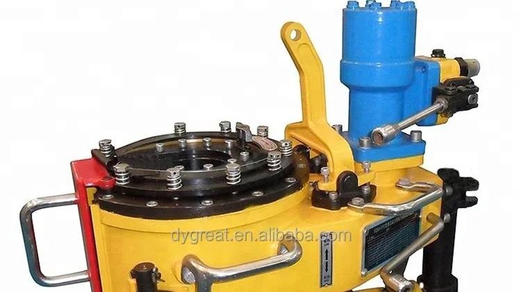
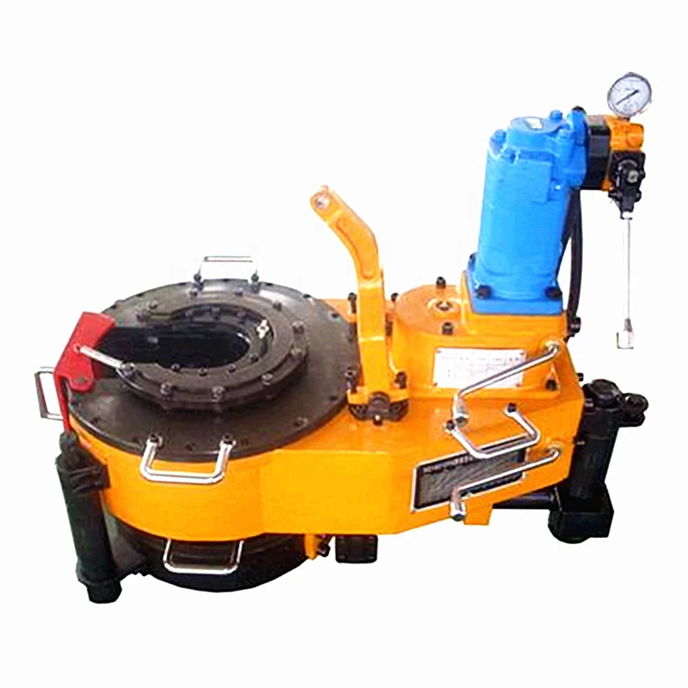
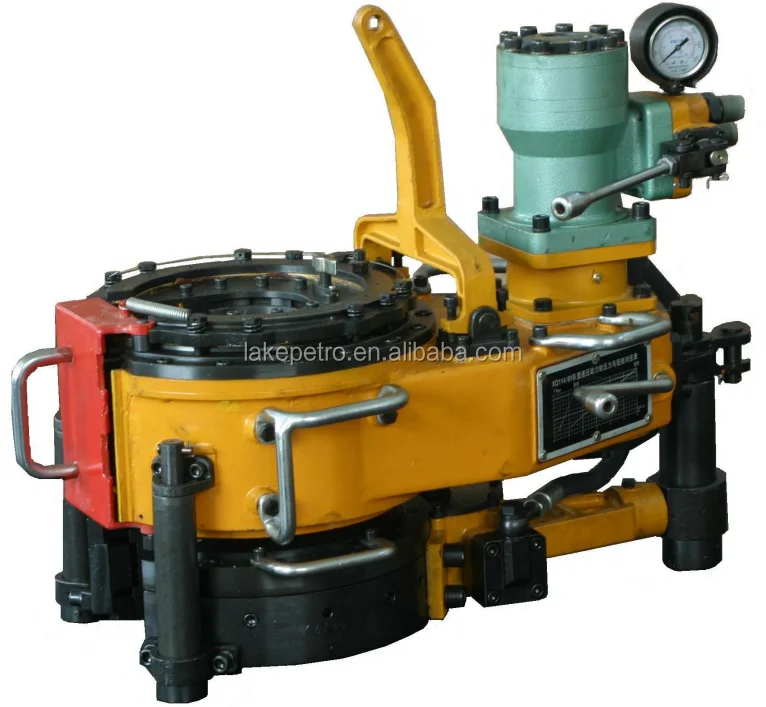
Model XQ28/2.6 hydraulic power tong is an improved type of XYQ1.8 which is used to make up and break out sucker rod thread in Well Service. This product has the following features:
A. The structure is compact, concise and light. Master tong is driven by a low-speed large torque hydraulic motor that matches with a manual control valve. The backup tong is just like a spanner. The total weight is approximately equal to XYQ1.8.
B. The operating is briefness and convenience with high efficiency. Put the respondence size jaw set into master tong and the respondence size glutting into backup tong, turning the reset knob incorrect direction then can make up and break out sucker rod by operating manual control valve. Two speed, snapping at low speed, spinning at high speed.

Magnum Manufacturing is a team of experienced casing running engineers and industry-leading professionals tired of working with existing substandard equipment. We have spent decades developing equipment to the highest industry standards, and we personally have been using the equipment we’ve developed. After 30+ years of partnering with a leading American TRS company to ensure optimal performance, we are prepared to stake our reputation on Performance, Longevity, & Safety.
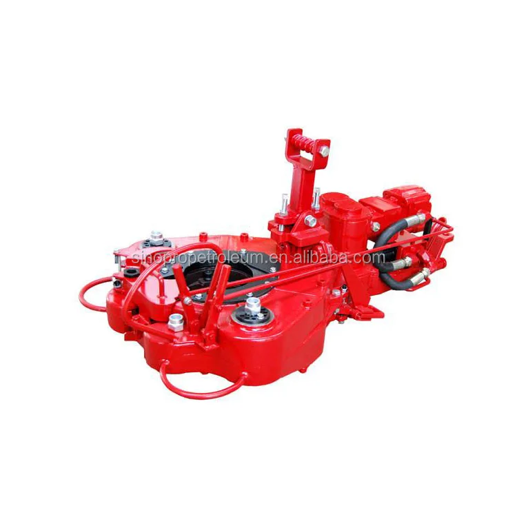
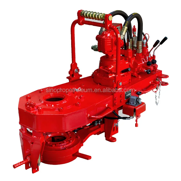
ZQ series of drilling pipe power tongs are a kind of perfect wellhead tools that can be extensively used in the fields of drilling or workover offshore and inland and upper unloading the pipe column screw thread during the workover job. The tongs have
the roles of enhancing the working efficiency, safety and labor-saving. These series of tongs are open-mouth type, can freely escape the pipe columns with very good maneuverability. The torque tongs and cupboard button tongs are
assembled as a whole, where upper unloading buttons replace the catheads, hanging tongs and spinning ropes. The power tongs conform to the SY/T5074 standards and API Spec 7K specifications.
A two-speed Hydra-Shift® motor coupled with a two-speed gear train provides (4) torque levels and (4) RPM speeds. Easily shift the hydraulic motor in low speed to high speed without stopping the tong or tublar rotation, saving rig time.
Used on corrosion resistant alloys (CRA) and fiberglass tubulars where reduced markings on the tubular is desired. Eckel"s Coated True Grit® Dies utilize Tungsten Carbide grit which provides many more points of contact on the surface of the tubular than our Pyramid Fine Tooth dies.
A patented door locking system (US Patent 6,279,426) for Eckel tongs that allows for latchless locking of the tong door. The tong door swings easily open and closed and locks when torque
is applied to the tong. When safety is important this locking mechanism combined with our safety door interlock provides unparalleled safety while speeding up the turn around time between connections. The Radial Door Lock is patented protected in the following countries: Canada, Germany, Norway, United Kingdom, and the United States.
The field proven Tri-Grip® Backup features a three head design that encompasses the tubular that applies an evenly distributed gripping force. The Tri-Grip®Backup provides exceptional gripping capabilities with either Eckel True Grit® dies or Pyramid Fine Tooth dies. The hydraulic backup is suspended at an adjustable level below the power tong by means of three hanger legs and allowing the backup to remain stationary while the power tong moves vertically to compensate for thread travel of the connection.
Eckel offers several models of torque control systems that are used to monitor the torque turn values when making up tubular connections (Tubing, Casing, & Drill Pipe). Any flaws in the make-up process will be readily shown in a graph.

The present invention relates to open-head power tongs used in drilling operations, and more particularly, is directed to an improved means of actuating and deactuating the operation of the power tong drive means in response to the opened and closed positions of an access door.
As well known in the drilling industry, power tongs are employed in making-up and breaking-out operations of casings, tubings, rods, pipes and the like. More particularly, power tongs are used to grip and rotate lengths of drill pipe or the like to connect or join several lengths of pipe together to thereby form a drill string in a make-up operation, and in the alternative, to grip and rotate a length of drill pipe to disconnect it from the drill string in a break-out operation.
One type of power tong commonly used today is the open-head tong, such as the one shown and described in U.S. Pat. No. 4,060,014. The open-head tong has a bifrucated frame defining a central opening and a side opening communicating with the central opening for the passing therethrough of a drill pipe or the like. Due to the extreme costs of drilling, open-head tongs have become very popular, in that, they can easily and readily be moved into and out of an operative position when they are needed in the making up and breaking out of drill strings.
In operation, the open-head power tong exerts large rotational torques on the drill pipes, usually the larger the tong, the larger the torque output. Due to these large torque outputs and the resulting forces generated therefrom, the open-head tongs have been provided with an access door that bridges the gap between the bifrucated ends of the tong. The primary purpose of such an access door is to strengthen the tong structure so as to prevent, during the operation of the tong, the bifrucated ends from separating or springing apart, which not only results in damage to the tong, but could also inflict injury to the operating personnel. The access door, in addition to providing structural rigidity to the tong, also provides the operator with safety in bodily protecting him from the rotating pipe gripping and engaging jaws.
Such access doors perform very satisfactorily in providing structural rigidity to the tong and do provide protection to the operators from the rotating components of the tong when the door is properly latched in position during the make-up and break-out operations; however, in an effort to save time, operators have been known to operate the tong with the access door open, and in some instances, the operators have even removed the access door from the tong. Such operator"s carelessness not only causes costly structural damage to the tong, but also results in personal injury to the operator.
In U.S. Pat. No. 2,705,614 there is shown an open-head power tong having an automatic hydraulically powered access door, operably interconnected to the hydraulic cylinders that actuate the jaw gripping mechanism, which must be closed before the jaws can be actuated so as to rotate a drill pipe. Such door interlock mechanism has been specifically designed for the type of tong disclosed and is not readily adaptable to other types of power tongs, such as the one shown in the above-mentioned U.S. Pat. No. 4,060,014. Further, the hydraulic circuitry that is involved with such a powered access door is not only complicated, having expensive components, but is also, costly to maintain and repair. Still further, such door interlock mechanism does not provide adequate safety to an operator, in that, although the operator is protected from the pipe gripping and engaging mechanism when the door is closed, he is also subjected to the risk of having the power operated door being automatically swung into him as it is being closed, thus, creating a potentially dangerous and unsafe condition under which the operator must work.
The present invention obviates the problems experienced with access doors and disadvantages associated with the prior art door-interlock mechanisms by providing, as one of its principle objects, an improved door-interlock mechanism for an open-head power tong that ensures the access door is in a closed position before the tong can be operated, thereby preventing possible structural damage to the tong from operating the tong with the door open, as well as, preventing personal injury to the operators by protecting them from the various rotating components of the tong.
Another object of the present invention is to provide a door-interlock mechanism for an open-head power tong that is simple in structure and adaptable to all types of open-head power tongs.
Accordingly, the present invention, sets forth in an open-head power tong having an access door mounted on the tong and moveable between opened and closed positions, an improved door-interlock mechanism that includes means for controlling the operation of the tong in response to the opened and closed position of the door. More particularly, the control means preferably includes a pneumatic contact valve interconnected with a pneumatically piloted diverter valve operably associated with the power means of the tong such that the power means is placed in either an operative or inoperative condition in response to respective closed and opened positions of the door. Specifically, the pneumatic contact valve is so positioned in the vicinity of the side opening that the door, in its closed position, engages the contact valve thereby actuating the diverter valve to permit operation of the power means, and when, the door is moved from its closed position out of engagement with the contact valve, the contact valve causes the diverter valve to deactuate the power means, thus stopping the operation thereof.
These and other advantages and attainments of the present invention will become apparent to those skilled in the art upon reading of the following detailed description when taken in conjunction with the drawings wherein there is shown and described an illustrative embodiment of the invention.
FIG. 1 is a top plan view of an open-head power tong incorporating the improved door-interlock mechanism of the present invention with the access door being in its closed position in engagement with the contact valve which actuates the diverter valve.
FIG. 2 is a diagrammatic fragmentary view of the power tong showing the side edge portion of the access door with the door latch removed and with the contact valve being in disengagement with the door which is partly open.
Referring to the drawings, and particularly, to FIG. 1, there is shown, for illustration purposes only, an open-head power tong, being generally indicated by the numeral 10, incorporating the principles of the present invention. The tong illustrated in FIG. 1 is of the type shown and described in U.S. Pat. No. 4,060,014, and thus, for the sake of brevity, since the tong itself forms no part of this invention, only a brief description of the tong will follow.
Briefly, as best seen in FIG. 1, the power tong 10 is comprised of a bifrucated frame structure 12 defining a central drill pipe receiving opening, and a side opening that communicates to the central opening for laterally passing a drill pipe therewithin. Rotatably supported within the frame structure 12 is a pipe engaging and gripping means that includes jaws 14 that swing into and out of the central opening for gripping and rotating a drill pipe disposed within the central opening during make-up and break-out operations of a drill string. The pipe engaging and gripping means with its associated jaws 14 are rotatably driven through a suitable drive train (not shown) by power means such as the hydraulic motor 16 which receives fluid under pressure from a suitable hydraulic pump (not shown) and through a hydraulic control valve 17. The valve 17 is conventional, being moveable between three spool positions; one position being such that the fluid drives the motor in a forward clockwise direction, another position being such that the hydraulic fluid drives the motor in a reverse counterclockwise direction, and the third position being a neutral position wherein fluid passes through the valve to the return line that returns the fluid to a reservoir (not shown) for recirculation thereof.
Also supported on the frame structure 12 is an access door 18, adapted to span or bridge the access opening defined between the bifrucated end portions so as to provide structural rigidity to the power tong 10, as well as, to protect the operator from the various moving components, such as the jaws 14. One end of the access door 18 is hinged to an end of one of the frame bifrucations by a pivot pin 20 whereas the free end of the door is provided with a self-latching arm 22 that engages a latch member 24 mounted on the other bifrucation so as to positively latch the door when it is closed. The door and the door latching mechanism are of the type shown and described in a pending U.S. application, bearing U.S. Ser. No. 791,752; filed Apr. 28, 1977; and entitled TONG LOCKING MECHANISM. The door and the latching mechanism forms no part of this invention and thus a further description will not be given.
To ensure that the tong 10 is only operated when the door 18 is closed, closing the access opening, the tong 10 is provided with an interlock mechanism which basically includes a contact valve 26, engageable by the door 18, and a hydraulic diverter valve 28, operably associated with the hydraulic motor 16 so as to permit flow of hydraulic fluid to the motor, or, in the alternative position, to bypass the flow of hydraulic fluid around the motor.
As seen in FIGS. 1 and 2, in particularly FIG. 2, the contact valve 26 is mounted on the front side of the frame structure 12, in proximity to the access opening, and is so positioned to be engaged by the door 18 when the door is closed and disengaged when the door is opened. The contact valve 26 has an internal spring that biases the valve to its disengaged position. A suitable source for generating pneumatic pressure, such as a compressor (not shown) is provided to supply pressure to the valve 26 through inlet line 30 and therethrough, when valve 26 is in its engaged position, via line 62 to one end of the pneumatic piloted hydraulic diverter valve 28. When pressure is so applied on the diverter valve 28, the valve is so positioned to permit hydraulic fluid to flow to the motor 16 and thereby its operation. However, when pressure is relieved from the diverter valve 28, which is caused when the door 18 is disengaged from the contact valve 26, an internal biasing spring forces the valve to a position which diverts the flow of hydraulic flow around the motor 16, and thus, stoppage thereof.
Now turning to FIG. 3 which schematically represents the various operating components as well as the hydraulic and pneumatic circuitry associated therewith, the operation of the door interlock will be further described. First, it should be noted that both the hydraulic source and the pneumatic source are fully operating with respective fluids being under pressure in inlet lines, the access door 18 being closed, engaged with the actuating arm of the contact valve 26, the piloted diverter valve 28 being detented so as to pass the flow of hydraulic fluid around the motor 16, and with the hydraulic spool control valve 17 being in its neutral position such that fluid passes directly therethrough to the reservoir tank via inlet line 34, passageway 36, return line 38. Thus, as the spool valve 17 is shifted to its forward drive position, hydraulic fluid passes from the inlet line 34, through passageway 40, to line 42, through passageway 44 (of diverter valve 28), to line 46 which directs fluid into the left-hand side of the motor 16, and then via lines 48,49 to passageway 50 of valve 18 which is internally connected to the hydraulic return line 38. If the spool valve 17 is shifted in an opposite direction so as to reverse the direction of the motor 16, fluid flows via line 34, through passageway 52 to line 49 and line 48 to the right side of the motor 16, and then returns via lines 46, passageway 44, line 42 to passageway 54 which is internally connected to return line 38. It can be thus seen that when pressure is applied on the diverter valve 28, it is so positioned to pass hydraulic fluid either to one or the other sides of the motor 16 to thereby drive the rotating components of the tong 10 in either forward or reverse directions depending on the forward or reverse positions of the control valve 17. However, when the pneumatic pressure is relieved from the diverter valve 28, the internal spring forces the valve to the right, thus changing the flow path of the hydraulic fluid so as to bypass the motor 16. In such pressure relief position of the diverter valve 28, the fluid flow path is via lines 49,58, passageway 56 and line 42, thereby bypassing the flow of fluid to the motor 16. Since the flow of fluid through line 46 is blocked, no fluid passes to the motor 16, thus rendering it inoperative.
Thus, it can be readily appreciated from the above, that hydraulic fluid is either directed to the motor 16 for operation thereof, or bypassed therearound, preventing its operation, depending on the position of diverter valve 28. The diverter valve 28 is caused to move between its respective positions in response to the engaged and disengaged positions of the contact valve 26. In its engaged position, air under pressure passes from inlet line 30 through passageway 60 to line 62 for applying pressure to the diverter valve 28 to thereby maintain it in its retracted position wherein hydraulic fluid is permitted to pass to the motor 16. However, when the access door 18 is opened, disengaged from the contact arm of the contact valve 26, the internal spring in the contact valve 26 moves the valve to the left, thereby relieving the pressure in line 62 by venting it to the atmosphere through passageway 64, causing the internal spring to shift the position of the diverter valve 28 such that hydraulic fluid flow is bypassed around the motor 16, thus non-operation thereof.
It can be understood from the foregoing that the described interlock-mechanism controls the operation of the hydraulic motor 16, and thus the operation of the tong 10, in response to the open and closed positions of the access door 18, such that the tong 10 can only be operated with the access door 18 in its closed position, and thereby eliminating the possibility of structural damage to the tong from operating same with the door open, as well as, providing safety to the operator from exposure to the various operating components of the tong.
It is thought that the invention and many of its attendant advantages will be understood from the foregoing description and it will be apparent that various changes may be made in form, construction, and arrangement of the improved door interlock mechanism without departing from the spirit and scope of the invention or sacrificing all of its material advantages, the form hereinabove described being merely a preferred or exemplary embodiment thereof.
High-pressure and flexible BOP hose asselies are used in crisis working conditions. As specified in API 16D, our BOP control lines are capable of containing the hose rated working pressure in a flame temperature of 1300°F (700°C) for a 5-minute period. BOP control lines are manufactured with 1/4" to 2" inside diameter and 5000 psi working pressure at aient …
Product. Description. Parker API 16D BOP hoses. Parker API 7K, 5k & 10k Cementing Hoses. Parker API 7K / 17J 10k Cementing / Acidizing Black Eagle Hoses. Dunlop, Argentina Monogrammed API 7K Rotary & Vibratory Hoses. Low Pressure Industrial Hoses for Cementing / Acidizing / Fracking / Diesel / Bentonite / Barite / Brine transfer.
12/8/2015· surface BOP’s. The intent in API 53 is to provide a weak link between the control system and the BOP because the fire retardant properties would be counter to the intended purpose of the emergency system. Since there are many vessel designs in operation it is not practical to have a different option for each. Sections 7.3.18 and 7.3.19 require floating rigs to …
BOP hose, well control hose, is a kind of high pressure, refractory, insulated hose assely. API 16D is applied to hydraulic control of drilling blowout preventer and hydraulic transmission of high temperature flammable site in metallurgical industry. It can be without fail under the maximum working pressure under teh lowest 700℃ flame temperture tests.
API BOP hose with high pressure and fast connector pipe fitting. $10.00-$50.00 / Meter. 10.0 Meters (Min. Order) CN SGPE.COM Limited. 1 YRS. Contact Supplier. 1/6. Food Grade High Pressure BREWERY HOSE with Tri-Clamp for Beer Brewery. Ready to Ship. $58.00 / Meter. 1 Meter (Min. Order) $62.93 /Meter (Shipping) CN Jinan Rainbow Machinery Co., Ltd. 12 YRS. …
API 16C Flexible Lines Author: SUNRY Subject: Flexible Lines (Blowout Preventer (BOP) Hydraulic Control Line and Flexible Choke Kill Line)features resistance to high-pressure, fire-resistance, heat-insulation and anti-flaming. They are in accordance with API Spec 16C. Keywords: Flexible Line, Flexible Chock Kill Line, Hydraulic control Line, BOP, Liquid Control …
•China’s first API authorized manufacturer of BOP Hose with a certifie of API Spe 16D •a patent for firstly producing the BOP Hose in China •80% shares for the domestic market •the first grade supplier of CNPC, SINOPEC and CNOOC •stainless steel 316 used as armored jacket . Factory Workshop: • SEJIN MACHINE from Korea. Suspension difference<70 MM, and the …
This API 16D specifiion requires hose asselies to withstand a particularly severe fire carried out under the following conditions: • Test duration: 5 minutes • Test temperature: 700°C • Water pressurised inside at WP • No fluid circulation • Proof pressure after test up to WP In contrast to other industry standard fire tests (eg: ISO 15540), the pressurised water inside the
API 16D BOP hose (BOP control hose) Structure: A structure of lining,reinforcement,flame-retardand and thermal insulation layer,and protection cover with coupling patent design. Property: Under temperature of 1093℃ (2000℉), the product can perform well for more than consecutive 5 minutes under working pressure. Standard: API Spec 16D.
13/7/2021· API Spec 7K, API Spec 16A and API Spec 16C was certified. The company was named high-tech enterprise in 2009. It has advanced production equipment, complete inspection measures, all sets of processing equipment of manufacturing high strength hose, mechanical machining, pressure vessel manufacturing, forging welding and heat treatment. Up to now
API 16D Blowout Preventer hose Our high-performance BOP hoses are designed for hydraulic use and certified to withstand fire, high heat and pressures in safety critical appliions. All Fire Armor BOP hose asselies are tested and approved by Lloyd’s Register, complying with American Petroleum Industry API 16D guidelines to meet and exceed
(BOP) hose. The Eaton EC556 blowout preventer hose system is a critical part of oil & gas drilling and exploration equipment, exceeds the requirements of API 16D - minimum of 700°C (1300°F) for 5 minutes - and is certified by Lloyd’s Registry. The specially-designed cover is abrasion-resistant and allows for greater flexibility and is easier to route than steel-armored …
1/7/2015· API 7K Rotary Drilling Hose Use: The drilling rotary hose is suitable for flexible connection between the top of the drilling riser and the swivel which can move vertically. It resists corrosion of hydrogen sulfide and can deliver water, oil, mud high‐pressure media. Standards: API Spec 7K, SY/T5469. Low Med High ; Flexibility: Cycle Life: Pressure Rating: Chemical …
s a red PKR rubber flame resistant sleeve that must be used for BOP hose assely in order to protect the fitting area and be approved in accordance with the API 16D flame test. The sleeve has to be fit over the fitting and doesn""t need any clamp to be fixed. Hose layline example FA35-12 19 mm (3/4") FIREARMOR 5000 BOP Part Nuers: FS-R-6, FS-R-8 WP 35,0 MPa (5000 …
•China’s first API authorized manufacturer of BOP Hose with a certifie of API Spe 16D •a patent for firstly producing the BOP Hose in China •80% shares for the domestic market •the first grade supplier of CNPC, SINOPEC and CNOOC •stainless steel 316 used as armored jacket. Factory Workshop: • SEJIN MACHINE from Korea. Suspension difference<70 MM, and the …
Oilfield Equipment, Drilling Tools manufacturer / supplier in China, offering Sucker Rod /API 11b/ D, Kd, Hl, Hy, Brass Sucker Rod Pump/API 11ax/Srp/Pumping Unit Pump/Brass Barrel, API Standard Xq28 Series Sucker Rod Hydraulic Power Tong for Oil Well and so on. Contact Supplier Company Favorites Company Favorites. Gold Meer Since 2021. Suppliers with …
Our high-performance BOP hoses are designed for hydraulic use and certified to withstand fire, high heat and pressures in safety critical appliions. All Fire Armor BOP hose asselies are tested and approved by Lloyd’s Register, complying with American Petroleum Industry API 16D guidelines to meet and exceed OD/1000/499 flame testing at 1300 °F for five minutes. …
Clause 9.10.6.2 of API Spec 7K specifies that hose end connections may be affixed to hose couplings with line pipe threads per API Spec 5B for hose asselies with a working pressure rating of 34.5 MPa (5,000 psi) or less. For rotary hose asselies wit h a working pressure greater than 34,5MPa (5000 psi) no threads of any kind may be utilized to affix the end …
Hydrasun specialist hose solutions allow customers to meet the stringent specifiions for BOP and well control for subsea and topside appliions. Hydrasun can supply firerated hoses and hotline hoses. Manpower installation package with containerised workshops for on-site testing & flushing efficiencies are also available.
BOP Hoses and Quick Couplings BOP equipment on drilling rigs is essential to ensure safety in the field. Required to perform under the harshest operational conditions, these systems can mean the difference between life and death for drilling rig operators. Manuli Hydraulics have developed two hose solutions designed specifically for BOP appliions: GoldenGuard - Available in …
BOP hose to API 16D, Lloyds OD1000/499 51 STH Teflon Hose Medium pressure steam laundry equipment, plastic moulding and air compressor discharge. Teflon liner / SS braid allow high temperature and chemical capability. 52 IPAF Pirtek-Flex Air General purpose blue air hose with cold weather formulation to maintain flexibility in cold conditions. Oil mist resistance. Conforms …
API 16D BOP Hose. BOP Hose 5, 000psi W.P. – 10, 000 psi Test-15, 000 Minimum Burst. Inquire Now + Select. Product list. Hydraulic rubber hose. SAE Standard; EN Standard; Multipurpose hose. Rotary Drilling Hose. Rotary Hose; Kelly Hose; Mud/Cement Hose; Vibrator/Jumper Hoses; Choke and Kill Hose Lines; Ultra High Pressure(15000psi Hose) API …
3/11/2021· API 6A Wellhead X-Mass Tree, API 16A Bop, API 16c Choke Manifold, Flowline Equipments, API 6A FC Gate Valves, Swivel Joint, Spacer Spool, API 6A Plug Valves, Hammer Union, Shear RAM Blowout Preventer City/Province
23/1/2013· between the control system and BOP stack shall be flame retardant, shall be capable of containing the hose rated working pressure in a flame temperature of 1300°F (700°C) for a 5- minute period.” Question: Is it required that flame retardant flexible piping outside an API 500, Division 1 classified area comply with the API 16D, Section 10.1.2 fire testing …
We also offer customer choke and kill hose lengths that can be made in much faster times than any other manufacture supplier in the world. API 16C Certifiion lloyds approved bop hoses. We are now offering api 16c certifiion as well as our already offered api 7k certifiion. On all fire proof bop hoses also they come with the Lloyds certified fire test cert that meets api 16c
•China’s first API authorized manufacturer of BOP Hose with a certifie of API Spe 16D •a patent for firstly producing the BOP Hose in China •80% shares for the domestic market •the first grade supplier of CNPC, SINOPEC and CNOOC …
The BOP Control system for surface mounted BOP stacks is used to open and close BOP and relief valve while drilling operation. It mainly consists of remote control panel, driller""s panel, air cable, pipe rack, high pressure hoses, protection house etc. WS ""s BOP Accumulator Units meet or exceed the design specifiion as specified in API 16D. Each control system is specifically …
23/8/2021· PME, China hose manufacturer and supplier, produce stainless steel armored hoses as API 16D guideline. We also test pressure to BOP hydraulic control hoses API 16D Specifiions for 15 mins. Today we""re happy to packing the new BOP control hoses as scheduled for our honored client. Call PME Team: +8613818990736 or Email: …
hose length calculation specified in API 7L, Section A.1.1, to determine the optimum length of a rotary hose for any given appliion to avoid over-bending, high axial load or compression during operation. For vibrator and jumper hose appliions, the purchaser shall take into account the change in length of the hose when it is pressurized as specified in 9.6.5 when specifying the …


 8613371530291