
hydraulic power tong books factory

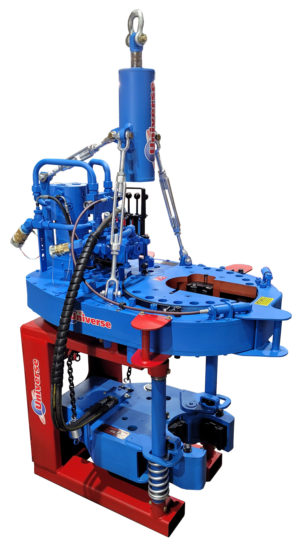
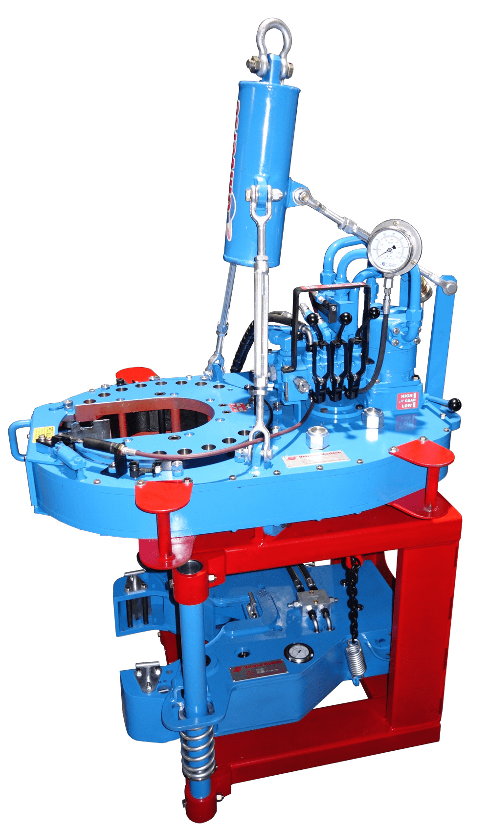
A two-speed Hydra-Shift® motor coupled with a two-speed gear train provides (4) torque levels and (4) RPM speeds. Easily shift the hydraulic motor in low speed to high speed without stopping the tong or tublar rotation, saving rig time.
A patented door locking system (US Patent 6,279,426) for Eckel tongs that allows for latchless locking of the tong door. The tong door swings easily open and closed and locks when torque
is applied to the tong. When safety is important this locking mechanism combined with our safety door interlock provides unparalleled safety while speeding up the turn around time between connections. The Radial Door Lock is patented protected in the following countries: Canada, Germany, Norway, United Kingdom, and the United States.
The field proven Tri-Grip® Backup features a three head design that encompasses the tubular that applies an evenly distributed gripping force. The Tri-Grip®Backup provides exceptional gripping capabilities with either Eckel True Grit® dies or Pyramid Fine Tooth dies. The hydraulic backup is suspended at an adjustable level below the power tong by means of three hanger legs and allowing the backup to remain stationary while the power tong moves vertically to compensate for thread travel of the connection.
Afghanistan - AFGAlbania - ALBAlgeria - DZAAmerican Samoa - ASMAndorra - ANDAngola - AGOAnguilla - AIAAntigua and Barbuda - ATGArgentina - ARGArmenia - ARMAruba - ABWAustralia - AUSAustria - AUTAzerbaijan Republic - AZEBahamas - BHSBahrain - BHRBangladesh - BGDBarbados - BRBBelarus - BLRBelgium - BELBelize - BLZBenin - BENBermuda - BMUBhutan - BTNBolivia - BOLBosnia and Herzegovina - BIHBotswana - BWABrazil - BRABritish Virgin Islands - VGBBrunei Darussalam - BRNBulgaria - BGRBurkina Faso - BFABurma - MMRBurundi - BDICambodia - KHMCameroon - CMRCanada - CANCape Verde Islands - CPVCayman Islands - CYMCentral African Republic - CAFChad - TCDChile - CHLChina - CHNColombia - COLComoros - COMCongo, Democratic Republic of the - CODCongo, Republic of the - COGCook Islands - COKCosta Rica - CRICote d Ivoire (Ivory Coast) - CIVCroatia, Republic of - HRVCyprus - CYPCzech Republic - CZEDenmark - DNKDjibouti - DJIDominica - DMADominican Republic - DOMEcuador - ECUEgypt - EGYEl Salvador - SLVEquatorial Guinea - GNQEritrea - ERIEstonia - ESTEthiopia - ETHFalkland Islands (Islas Malvinas) - FLKFiji - FJIFinland - FINFrance - FRAFrench Guiana - GUFFrench Polynesia - PYFGabon Republic - GABGambia - GMBGeorgia - GEOGermany - DEUGhana - GHAGibraltar - GIBGreece - GRCGreenland - GRLGrenada - GRDGuadeloupe - GLPGuam - GUMGuatemala - GTMGuernsey - GGGuinea - GINGuinea-Bissau - GNBGuyana - GUYHaiti - HTIHonduras - HNDHong Kong - HKGHungary - HUNIceland - ISLIndia - INDIndonesia - IDNIreland - IRLIsrael - ISRItaly - ITAJamaica - JAMJapan - JPNJersey - JEJordan - JORKazakhstan - KAZKenya - KENKiribati - KIRKorea, South - KORKuwait - KWTKyrgyzstan - KGZLaos - LAOLatvia - LVALebanon - LBNLiechtenstein - LIELithuania - LTULuxembourg - LUXMacau - MACMacedonia - MKDMadagascar - MDGMalawi - MWIMalaysia - MYSMaldives - MDVMali - MLIMalta - MLTMarshall Islands - MHLMartinique - MTQMauritania - MRTMauritius - MUSMayotte - MYTMexico - MEXMicronesia - FSMMoldova - MDAMonaco - MCOMongolia - MNGMontenegro - MNEMontserrat - MSRMorocco - MARMozambique - MOZNamibia - NAMNauru - NRUNepal - NPLNetherlands - NLDNetherlands Antilles - ANTNew Caledonia - NCLNew Zealand - NZLNicaragua - NICNiger - NERNigeria - NGANiue - NIUNorway - NOROman - OMNPakistan - PAKPalau - PLWPanama - PANPapua New Guinea - PNGParaguay - PRYPeru - PERPhilippines - PHLPoland - POLPortugal - PRTPuerto Rico - PRIQatar - QATReunion - REURomania - ROURussian Federation - RUSRwanda - RWASaint Helena - SHNSaint Kitts-Nevis - KNASaint Lucia - LCASaint Pierre and Miquelon - SPMSaint Vincent and the Grenadines - VCTSan Marino - SMRSaudi Arabia - SAUSenegal - SENSerbia - SRBSeychelles - SYCSierra Leone - SLESingapore - SGPSlovakia - SVKSlovenia - SVNSolomon Islands - SLBSomalia - SOMSouth Africa - ZAFSpain - ESPSri Lanka - LKASuriname - SURSwaziland - SWZSweden - SWESwitzerland - CHETaiwan - TWNTajikistan - TJKTanzania - TZAThailand - THATogo - TGOTonga - TONTrinidad and Tobago - TTOTunisia - TUNTurkey - TURTurkmenistan - TKMTurks and Caicos Islands - TCATuvalu - TUVUganda - UGAUkraine - UKRUnited Arab Emirates - AREUnited Kingdom - GBRUnited States - USAUruguay - URUUzbekistan - UZBVanuatu - VUTVatican City State - VATVenezuela - VENVietnam - VNMVirgin Islands (U.S) - VIRWallis and Futuna - WLFWestern Sahara - ESHWestern Samoa - WSMYemen - YEMZambia - ZMBZimbabwe - ZWE
のための高いトルクを得るトングに関するものである。Description: FIELD OF THE INVENTION The present invention relates to power tongs used to connect or disconnect pipe members, and in particular to backup tongs used to secure the pipe members against rotation. It is about. The present invention also relates to scissor-type tongs, wherein the upper body portion rotates relative to the lower body portion to obtain a high torque for connecting or disconnecting, which is normally required for a drill pipe. It is a thing.
えられるとき、下管状部材の回転が生じ得る。BACKGROUND OF THE INVENTION AND PROBLEMS TO BE SOLVED BY THE INVENTION Powered rotary tongs typically cause an upper tubular member (eg, casing, drill pipe or tube) to rotate relative to a fixed lower tubular member, thereby Used to connect or disconnect members in a screwdriver relationship.
Otherwise, rotation of the lower tubular member may occur when high torque is applied to the upper tubular member by the powered rotary tongs during the initial disconnecting action or the final connecting action.
Manual or powered backup tongs are used. Generally, tong operators prefer powered backup tongs to manual backup tongs. Examples of manual backup tongs are described in US Pat. Nos. 2,668,689 and 3,380,323. Such manual tongs usually require additional work by the operator,
No. However, a drawback of such backup tongs is that the external force used to properly grip the pipe to prevent rotation is so great that it is crushed. In addition, closed throat backup tongs such as those shown in US Pat. No. 3,518,903 require a lot of field adjustment, thus tending to delay expensive oil recovery operations, as well as pipe sections (joints of pipes). However, it cannot be placed laterally and cannot be removed laterally.
が脱着され得る。U.S. Pat. No. 4,290,304 discloses an improved backup tong. The patent shows a cage plate assembly that carries multiple heads and that is rotated by a hydraulic motor. As the cage plate assembly rotates, the head is driven inward,
The cam surface of the cam ring fixed to the tongue body engages the pipe. The tongs use support lugs fixed to the tongue body and support pins attached to the cage plate to automatically align the cage plate openings with the openings in the tongs body, thus removing the tongs from the pipe laterally. Can be done.
ている。Power tongs according to the prior art are tongs, commonly called scissor-type tongs, in which the upper tongue body holds the upper pipe section, the lower tongs body holds the lower pipe section, and then these tongue bodies rotate relative to each other. And adapted for screwdriver connection or screwdriver disconnection of pipes. Generally, only 10 °
It is only used to provide the final connecting and disconnecting torques needed for some drill pipe operations. Therefore, spinners are often used to couple (screw) the drill pipe sections together in a screwdriver relationship, and the scissor torque is the final 30 ° angle of coupling rotation that requires an extremely large torque. Or only used for the first 30 ° angle of separation rotation. The spinner and scissor tongs can be combined into a single device, an example of which is US Pat. No. 2,705,614.
39 and 2871743, in which a swingable lever acts to engage each pipe section. In a variation of the scissors-type tongs shown in US Pat. No. 2,760,392, the upper and lower yoke members rotate relative to each other.
とは不可能である。Many of the disadvantages of the scissors-type tongs are that they require an extremely large amount of work to carry out the connecting or disconnecting work. The scissors-type tongs also have some of the drawbacks already pointed out in connection with certain backup tongs. That is, to prevent rotation between the head and the pipe, the power device for full grip of the pipe is so strong that the head will crush or damage the pipe. In addition, scissor-type tongs typically use assisting devices that align the throat portions of the tongs with one another, but such assisting devices further add to the workload of the operator or are unreliable, and The tongs cannot be easily and reliably attached to and removed from the pipe by lateral movement.
473 and 4082017. In the conventional scissor-type tongs disclosed in the latter, the upper and lower tong portions serve to grip the upper pipe section and the lower pipe section, respectively. As shown in U.S. Pat. No. 4,082,017, the upper and lower tong sections are rotated by a cylinder interposed therebetween.
ート組立体に結合される。Means for Solving the Problems, and Actions According to the present invention, a cage ring coupled in a tongue body and a cage plate assembly capable of rotating relative to the cam ring and carrying a plurality of heads. , A backup tong including a pair of hydraulic cylinders connected at each end to a pivot rod pivotally connected to the tong body. One of the hydraulic cylinders is connected at the other end to the tongue body and the other hydraulic cylinder is connected at the other end to the rotatable cage plate assembly.
て容易にトングが着脱可能である。According to one feature of the present invention, the tongue body and the cage plate assembly each have a throat opening (not a throat opening with a full circumference, but a throat opening with a part of the circumference open). And therefore the tongue is removable from the pipe laterally. One of the hydraulic cylinders is fully extended, while the other hydraulic cylinder is fully retracted, thereby aligning the throat cage plate assembly with the tongue body, thereby facilitating easy access to the pipe. The tongs are removable.
レート組立体の連結または分離回転を可能にする。According to another feature of the invention, the cylinder end of each hydraulic cylinder is pivotally coupled to the pivot rod, while the rod end of each hydraulic cylinder is pivotally coupled to the tong body or cage plate assembly. To be done. The cylinders are dimensioned to provide approximately the same maximum output when both cylinders are extended or retracted, and the pivot point of the pivot rod is a swingable hydraulic cylinder. It is located approximately in the center between the two points of connection with the pivot rod. The two cylinders cooperate with the pivot bar to allow interlocking or uncoupling rotation of the cage plate assembly by extension or retraction movements of both cylinders.
The hydraulic cylinder operates to rotate the pivot rod and the other hydraulic cylinder operates to increase or decrease the distance between the pivot rod end and the connection point between the rod end of the cylinder and the cage plate. The cage plate assembly can be rotated by a combination of two cylinders and a pivot bar over an angle greater than that allowed by only one of the cylinders. In other words, it is possible to further reduce the size of the tongue by the above characteristics. This is because each hydraulic cylinder need not be the same length as a single cylinder that can rotate the cage plate assembly in the same angular range as described above during a single stroke.
大のケージプレート回転力が得られる。According to yet another feature of the invention, each cylinder is in a retracted position during a pipe separating operation, and thus, after the separating operation is completed, each cylinder is extended to separate the head from the pipe. Maximum cage plate rotational force is obtained by supplying hydraulic pressure.
るように作用する。According to another feature of the invention, the backup tongs described herein are used to construct scissor tongs having upper and lower tong bodies for gripping the upper and lower pipe sections, respectively. Can be done. Another hydraulic cylinder is coupled between the upper and lower tongs bodies and acts to rotate the upper tongs body relative to the lower tongs body to provide high torque for pipe connection or disconnection. .
グが開示されており、該特許を本明細書に援用する。EXAMPLE FIG. 1 shows a power rotating tongue 10 used with a backup tong 22 according to the present invention for connecting and disconnecting threaded tubular members such as casings, drill pipes and tubing commonly used in oil recovery operations. It is a schematic side view of. The powered rotary tong 10 has a body 12 and a controller 14 for rotating the cage plate assembly 16 relative to the body to connect or disconnect the pipe connections. The power swivel tong 10 is of the throat type and has a door 18, so that the power swivel tongue 10 can be detachably attached to the pipe laterally. U.S. Pat.Nos. 3,261,241, 3,380,323, 35,504
No. 85 discloses a suitable powered rotary tongue. U.S. Pat. No. 4,084,453 discloses a powered rotary tongue that is particularly suitable for use with the backup tongs of the present invention, which patent is incorporated herein by reference.
許を本明細書に採用する。As explained in more detail below, the backup tongs 22 have a tongue body 24 and a pair of hydraulic cylinders attached to the tongue body 24 for rotating the cage plate assembly 28 (first). Cylinder 26 is shown in the figure). Further, the tongue body 24 has a throat opening portion, which can be opened and closed by the door 30, so that the power rotating tongue 10 and the backup tongue 22 can be simultaneously detachably attached to the pipe in the lateral direction. The power rotating tongs body 12 and the backup tongs body 24 are coupled to the power rotating tongs 10 and substantially prevent relative rotation by a plurality of legs 20 extending through a plurality of holes formed in the backup tongs 22. Has been done. The backup tongs 22 are supported on springs 36. Spring 36 is retained by a suitable adjustable spring stop 38 mounted on leg 20. In addition, the lowering member 38 attached to the power rotating tongs 10 provides the backup tongs 2 to provide a direct read-out of the connecting torque.
2 engages with the load cell 34 disposed on the upper side of the upper part 2 and prevents the upper and lower tongs bodies 12, 24 from rotating during the coupling operation. Details regarding leg 20 and load cell 34 are disclosed in US Pat. No. 4,402,239, which is incorporated herein by reference.
FIG. 4 is a top view of the same number is used for the previously described device. The tongs body 24 is composed of a top plate 40, a bottom plate substantially equivalent to the top plate, and a side wall portion between the both plates. The cage plate assembly 28 is rotatably attached to the tongs body 24 by a plurality of rollers secured by cage plate bolts 42. A preferred door 30 is shown as having a latching device 44 for minimizing the expansion of the thoracotong body under high torque.
An ear piece 68 attached to the is attached swingably at 70. The pivot rod 54 swings around a pin 56 protruding upward from the top plate 40. The pin 56 is conveniently aligned with the center of the throat portion of the tongs body 24 to receive the pipe laterally.
And the cylinder 26 cooperate to rotate the cage plate assembly 28 relative to the tongue body 24 and automatically align the throat portion of the cage plate assembly 28 with the throat opening of the tong body 24. To do.
ている。FIG. 2 also shows suitable holes 48,50 penetrating both the top and bottom plates of the tongue body 24 for receiving the downwardly extending legs 20. An arm 52 extending from the rear of the tongs body 24 supports the load cell 34. The cage plate assembly 28 includes a pair of swingable heads 72.
And each head carries a cam roller 74 which engages a camming surface of a cam ring 76 coupled to the tongue body 24. The cam working surface of each head 72 is a separate cam surface 78,
It includes a connecting cam surface 80 and a neutral cam surface 82. Details of a suitable cam ring coupled to the top and bottom plates of the tongs body 24 and a suitable cage plate assembly using a sliding head are described in further detail in U.S. Pat. Further details regarding another preferred embodiment of the camming surface of a conventional cam ring and cage plate assembly are set forth in U.S. Pat. No. 4,084,453.
よって決定される。Referring to FIG. 3, a simplified top view of the device shown in FIG. 2 is depicted. It will be appreciated that the cage plate assembly 28A is maintained in the neutral position when the cylinder 46A is fully extended and the cylinder 46B is fully retracted. The pivot pins 56, 56A are fixed relative to the tongs body 24, and thus the position of the pivot rod 54A and the pihot pin 6A.
よる下パイプのつかみ力が得られることになる。To move the backup tongue 22 of the present invention from its neutral position to a position that prevents rotation of the lower pipe when the upper pipe is being coupled by the power rotating tongs, the cylinder 26B is extended as shown in FIG. It can be operated. Extension of the rod 64 from the cylinder 26 causes the cage plate assembly 28B to rotate, as shown, so that each cam roller 74 engages the connecting cam surface 80 offset from the neutral position of the stationary cam ring 76, causing the head 72 to move downwardly. The gripping force of the pipe will be obtained.
を阻止する。To move the backup tongue 22 from its neutral position to a position that prevents rotation of the lower pipe when the upper pipe is being separated by the power rotating tongs, the cylinder 46C is retracted as shown in FIG. To be Retraction of rod 62 into cylinder 46 causes rotation of pivot bar 54 about pin 56, thereby causing rotation of cage plate assembly 28C as shown. Therefore, each of the cam rollers 74 moves relative to each other along the separating cam surface 78 of the fixed cam ring 76, preventing substantial rotation of the lower pipe during the separating operation.
The grip claw portion (die) of the head 72 grips the pipe after each cam roller moves along the cam surface by a distance of inch. Thus, the maximum stroke of each cylinder is set such that after the head 72 enters the gripping engagement with the pipe, the cage plate assembly continues to rotate and further move the cam rollers relative to the cam surface. There is also an adjustable pressure regulating valve on the hydraulic lines to the cylinders 26, 46 so that the maximum pressure on each cylinder is the value required to ensure a strong gripping engagement of the head 72 with the pipe, eg about 105 kg / cm 2 (1500psi
), Is desirable. In accordance with standard practice in power tongs, the head 72 associated with the backup tongue 22 of the present invention is readily interchangeable, so the particular head size used with the backup tongue 22 should be grab and engage. It is determined according to the diameter of the pipe. The controller 15, which regulates the pressure on each cylinder 26, 46, is located on the backup tongs body, or adjacent the controller 14 of the rotary tongue or power rotary tongue 10, as shown in FIG. Is located. In addition, in FIG.
An exemplary pressure regulating valve 17 for controlling fluid pressure to 6,46 is depicted. Neither standard flexible fluid tubes for power rotating tongs and backup tongs nor skid mounted hydraulic power units are shown in FIG.
イプへ伝達される把持力がさらに増大可能である。After the cylinders 26,46 have grabbed the head 72 into engagement with the pipe, the cylinders 26,46 are generally retracted or extended, as shown in FIGS. 4 and 5. . The hydraulic pressure to these cylinders is interrupted during the actual connecting or disconnecting operation, or the pressure on said cylinders is maintained during this operation. As those skilled in the art will appreciate, torque is transmitted to the lower pipe as the upper powered rotary tongs rotate the upper pipe. Thus, the torque transmitted to the lower pipe causes the cage plate assembly 28 to rotate further relative to the backup tongs body 24,
It is not necessary to give it to 2. These cylinders only require the gripping claws (dies) of the head to provide sufficient force to grip the pipe, after which the gripping force from the head 72 to the pipe causes the rotary power tongs 10 to move against the pipe. It is transmitted, and the cage plate assembly is moved in the same direction, and the cam roller of the head 72 moves relatively along the cam surface, whereby the gripping force transmitted from the head 72 to the pipe can be further increased.
しようとしないからである。One of the advantages of the fixed cam ring / rotating cage plate method as described above in the backup tongs is that the lower tongue has an unnecessary grip force than is necessary to ensure that the backup tongs do not rotate the lower pipe. In other words, actuation of cylinder 26 or 46 causes the cam roller of head 72 to move relative to the cam surface by approximately 6.35 mm (1/2 inch) from the end position of the neutral cam surface. , At that position, the head 72 is in gripping engagement with the pipe. Thereafter, the pressure in the cylinder is released, and the cam roller of the head 72 can remain in the position where the torque was first applied to the upper pipe by the rotary power tongs. Furthermore, when additional torgue is fed to the upper pipe,
The lower pipe also tends to rotate in the same direction (perhaps by 2 ° to 5 °), which may further move the cam roller relative to the cam surface. Thus, when the final connecting torque is supplied by the rotary power tongs, an additional gripping force is exerted on the pipe by the backup tongs, holding the lower pipe and preventing its substantial rotation, but of the backup tongs. The force transmitted by the head 72 to the lower pipe is not unnecessarily great enough that the lower pipe is crushed by the backup tongs. Thus, the gripping force provided by the backup tongs reacts automatically and directly to the torque produced by the rotary power tongs. Cylinder 2 depending on the characteristics such as
It is clear that the 6,46 can be relatively lightweight and still maintain reliability. This is because the cylinder does not try to react to the torque supplied to the pipe by the rotary power tongs.
Since it is directly related to being resisted by the tongs, the maximum desired force from the cylinders 26, 46 will be present after the separating operation and the cylinder will overcome the back-biting problem and place the cage plate assembly in the neutral position. It would be preferable to be able to exercise to return to. If the sliding head is provided in the cage plate assembly of the backup tongs, the cage plate assembly is rotated back to the neutral position and at the same time a biasing device (e.g. a spring) to retract the sliding head. Can be used. One configuration of a suitable sliding head and biasing device is disclosed in U.S. Pat. No. 4,290,304, which is incorporated herein.
号に開示されており、該発明は本明細書に援用される。FIG. 6 is a rear view of the preferred scissor tongs 84 in accordance with the present invention. The scissors tongs 84 have an upper body assembly 86 and a lower body assembly 87, each of which is structurally and operationally similar to the backup tongs previously described. That is, the upper body 86 has a pair of cylinders 90, 92, each cylinder being coupled at one end to a pivot bar 88 for rotating the cage plate assembly relative to the body. The lower body 87 includes a pair of cylinders 91, 93, each cylinder being connected at one end to a pivot rod 86 for rotating the cage plate assembly relative to the body. In order to allow the upper body 86 and the lower body 87 to be in a physical proximity relationship (particularly desirable for connecting a drill pipe), the cylinders 91, 93 and the pivot rod 89 are provided on the lower tongue plate of the lower body 87. It is arranged below. The main difference between the scissor tongs shown in FIG. 6 and the tongue assembly shown in FIG. 1 is that the upper body 86 and the lower book 87 are configured to rotate relative to each other like scissors. It is that you are. This rotation is conveniently produced by hydraulic cylinder 96. The hydraulic cylinder 96 is swingably connected to the lower body 87 at its cylinder portion, and is swingably connected to the member 94 at its rod end 98.
The member 94 is fixedly coupled to the upper body 86. Further details regarding the operation of the preferred scissors tongs and the mounting of the preferred hydraulic cylinder 96 can be found in US Pat. No. 4,084,417.
と同じである。During the pipe connecting operation, the hydraulic cylinder 96 is first extended so that the tongs are opened, that is, with the tongue assembly 87 viewed from above, the upper body 86 is counterclockwise relative to the lower body. It is rotated 15 ° in the direction. After that, the cylinders 90 to 93 of the upper body 86 and the lower body 87 are
Is operated, whereby the grip claw portions (dies) of the upper body and the lower body are brought into a gripping engagement relationship with the pipe. The cylinder 96 is then retracted and the upper cylinder (when the tongue assembly is viewed again from above) is moved clockwise relative to the lower cylinder, thus threading the upper pipe relative to the lower pipe. . Once the cylinder 96 has been retracted, the cylinders 90 and 92 are actuated again to disengage the head of the upper body 86 from the engagement with the pipe, after which this process causes the cylinders 91 and 93 to move to the lower body. Repeated with the die still engaged with the lower pipe. During the pipe separating operation, the upper and lower tongs bodies are first aligned with each other, the cylinders 90-93 are operated so that the head grips the upper and lower pipes, and the cylinder 96.
Is extended to rotate the upper tongue body in the counterclockwise direction relative to the lower tongue body. As already mentioned, the scissors tongs 84 are conventionally used only when producing the final desired connecting torque or when initially disengaging the screw connection. Therefore, a separate spinner device (not shown) is conventionally provided for connecting or disconnecting the screw connections, with which the scissor tongs are used only to provide the final connecting torque, or the initial separating torque. FIG. 7 shows the cylinders 90, 91, 92 in the neutral position,
93 shows the position of 93, the broken line represents the cylinder and the pivot bar for the lower tongue body 87, the solid line the upper tongue body 86.
Represents a cylinder and a pivot rod for. Obviously, the cage plate assembly of the upper tongue body 86 and the lower tongue body 87 must rotate in the same direction during the pipe connecting or disconnecting operation. This is achieved by extending the cylinder 92 of the upper tongue body 86 and extending the cylinder 92 of the lower tongue body 87 in the connecting operation. In the separating operation, all four cylinders 90, 91, 92, 93 are moved backward. It also takes into account the maximum force from the cylinder to overcome the "back-biting" or return bite to return the cylinder to the neutral position after completion of the separating operation. In the present example, the actuation of cylinder 96 causes relative rotation of lower body 87 and upper body 86, thereby accomplishing the task of connecting or disconnecting the connections with the desired torque. Preferably, the cylinder 96 is formed as shown in FIG. 6 so that the maximum force from the cylinder 96, which is obtained when the cylinder 96 is extended, is generated during the separating operation rather than during the connecting operation. It During operation of the cylinder 96, the cage plate assembly of the upper tongue body 86 and the lower tongue body 87 increases the gripping force in the pipe by several degrees (°).
図される。The above embodiments are merely illustrative of the principles of the present invention. The backup tongs and scissor tongs described herein can use sliding or hinged heads. Also, the cage plate assembly of such devices is supported by and rotatably guided by suitable cage plate rollers which engage the partial ring members and / or tong plates.
As shown in FIG. 6, a hydraulic cylinder for rotating the cage plate assembly relative to the tongs body is provided on the top plate or below the bottom plate. Also, the width of the tongue body must be increased to prevent contact between the cylinder and the cage plate assembly, but it is desirable to provide these hydraulic cylinders and rocking rods between the upper and lower tongs plates. Many modifications and variations can be made within the scope of the invention. The modifications described above and other modifications apparent to those skilled in the art are intended to be within the spirit and scope of the invention.
Figures in which a portion of the cage plate assembly has been removed to reveal internal components; Figures 3, 4 and 5 show the cage plate assembly in a neutral, coupled and disengaged mode, respectively. FIG. 6 is a simplified top view showing the relative positions of the hydraulic cylinder and the pivot rod; FIG. 6 is an end view of the preferred scissor-type tongs according to the present invention;
FIG. 6 is a simplified top view showing the interrelated positions of the upper and lower cage plate rotating cylinders and the pivot bar of the present invention in the neutral position. 10: power rotating tongs, 22: backup tongs,


 8613371530291