
kt 5500 power tong in stock
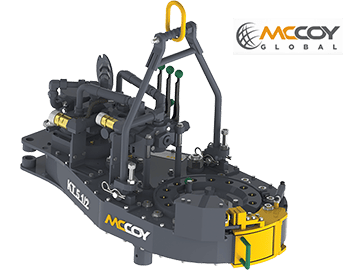
The KT5500 hydraulic power tong can handle tubulars as small as 2-1/16″ and as large as 5-1/2″ in diameter. Wraparound jaw and die technology for the two tong jaws is available. Also available with low-marking CHROMEMASTER™ “softgrip” jaw assembly mated to a 5-1/2″ tong. Tong can be mounted on either a CLINCHER® or FARR® hydraulic backup. Available with McCoy’s patented WinCatt® data acquisition and torque control system for the make-up of tubular connections.

The FARR® KT5500 hydraulic tubing tong can handle tubulars as small as 2-1/16" and as large as 5-1/2" in diameter. Wraparound jaw and die technology for the two tong jaws is available. Also available with low-marking CHROMEMASTER™ "softgrip" jaw assembly mated to a 5-1/2" tong. Tong can be mounted on either a CLINCHER® or FARR® hydraulic backup. Available with McCoy"s patented WinCatt® data acquisition and torque control system for the make-up of tubular connections.

Tongs - Power - BJ sucker rod tong adopts advanced sucker rod or tubing technology and has a compact structure, high reliability and is safe and convenient to operate.
Tongs - Power - New Carter Tool Co. Inc., CT93R Hydraulic powered tubing tong. Complete with 2-3/8" to 3-1/2" jaw assemblies, standard motor, torque gauge assembly, pressure relief valve... More Info
Tongs - Power - New Carter Tool Co., Inc. 5-1/2" CTSX Hydraulic Tubing Tong with heavy case and cover; complete with rigid hanger assy., suspension spring assy., front end control assy.,... More Info
Tongs - Power - New Carter Tool Co. Inc. M-Series power sucker rod tongs, complete with spring hanger assy., gate assy., front end control assy., pressure gauge assy., two 90 degree XH s... More Info
Tongs - Power - New Carter Tool Co., Inc. 4-1/2" RSX Hydraulic Tubing Tong with heavy case and cover; complete with rigid hanger assy., suspension spring assy., front end control assy., ... More Info
Tongs - Power - D D 58-93-2-R Power Tubing Tong is smaller, lighter, and faster than the Foster 5893R. The D D 58-93-2-R Tong is capable of gripping tubulars from 1 5/16" to 7" o.d. More Info
Tongs - Power - FARR TONG MODEL KT 14,000 RINEER GA37 MOTOR, LIFT VALVE ASSEMBLY TORQUE CAPACITY: 50,000 FT/LB SIZE RANGE 4 1.2-14 WITH SAFETY DOOR MOST SIZES OF FARR POWER TONGS ARE IN ... More Info
Tongs - Power - FARR TONG MODEL KT20,000 STAFFA 080 MOTOR, LIFT VALVE ASSEMBLY TORQUE CAPACITY: 50,000 FT/LB SIZE RANGE: 7-20 MOST SIZES OF FARR POWER TONGS ARE IN HOUSTON, IN STOCK READ... More Info
Tongs - Power - FARR MODEL KT5500 HYDRAULIC TUBING TONG C/W 2 SPEED RINEER MOTOR, SIZE RANGE: 2-3/8 IN. - 5-1/2 IN. OD, TORQUE RTED: 18,700 FT/LB C/W SAFETY DOOR MOST SIZES OF FARR POWER... More Info
Tongs - Power - FARR TONG MODEL KT5500 TORQUE CAPACITY: 18000 FT/LB SIZE RANGE: 2 1/16-5 1/2 OD WITH SAFETY DOOR MOST SIZES OF FARR POWER TONGS ARE IN HOUSTON, IN STOCK READY FOR IMMEDIA... More Info
Tongs - Power - FARR TONG MODEL KT5500 5 1/2 IN. TONG TORQUE CAPACITY: 18,000 FT/LB SIZE RANGE: 2 1/16-5 1/2 IN. OD, RINEER 15-13 MOTOR, HIGH TORQUE CLINCHER BACKUP TRIPLE VALVE ASSEMBLY... More Info
Tongs - Power - FARR TONG MODEL KT7585 TORQUE CAPACITY: 25000 FT/LB SIZE RANGE: 2 1/16-8 5/8 OD WITH SAFETY DOOR MOST SIZES OF FARR POWER TONGS ARE IN HOUSTON, IN STOCK READY FOR IMMEDIA... More Info
Tongs - Power - FARR TONG MODEL KT7585 8 5/8 IN. TONG TORQUE CAPACITY 25,000 FT/LB SIZE RANGE: 2 1/16-8 5/8 IN. OD, RINEER 15-15 MOTOR CLINCHER BACKUP, TRIPLE VALVE MOST SIZES OF FARR PO... More Info
Tongs - Power - FARR TONG MODEL LW9625 TORQUE CAPACITY 12000 FT/LB SIZE RANGE 2 7/8 -9 5/8 OD WITH SAFETY DOOR MOST SIZES OF FARR POWER TONGS ARE IN HOUSTON, IN STOCK READY FOR IMMEDIATE... More Info
Tongs - Power - Farrs newest tubular connection tool offers a significantly reduced rig footprint, while continuing to deliver power & uncompromising reliability. The simple design drast... More Info
Tongs - Power - Farr Canada"s newest tubular connection tool offers a significantly reduced rig footprint, while continuing to deliver power and uncompromising reliability. The simple de... More Info

Tongs - Power - Farr KT5500 Tubing Power Tongs w/Jaw Die Power Tongs, 5-1/2" available with or without back-ups. KT5500 18K Tongs with hydraulic Clincher Back-up TORQUE TABLE Pressure H... More Info
Tongs - Power - McCoy KT8625 8-5/8" Casing Tong - 25K Tong Power Tongs - (Our KT7585 Model Is Being Rebadged as KT8625. There Have Been No Design Changes to this Tong, It Still Function... More Info

mccoyglobal.comCopyright © 2007 - 2012 McCoy Corporation. All rights reserved.Published by McCoy Corporation, Technical Publications Department14755 - 121A Avenue • Edmonton, AB, Canada, T5L 2T2 KT5500 5-1/2” 18.7K Tong
TONG MODEL REV DESCRIPTION “Backup ready” tong with Rineer motor, motor valve, backup valve, lift cylinder 80-0420-3 1 valve, rigid sling, and safety door. 80-0420-5 1 Tong with Rineer motor, motor valve, rigid sling, and safety door. 80-0420-6 1 Tong with Rineer motor, motor valve, lift cylinder valve, rigid sling, and safety door. “Backup ready” tong with Rineer motor, motor valve, backup valve, lift cylinder 80-0420-9 1 valve, rigid sling, & safety door. CLOSED CENTRE SYSTEM 80-0420-12 1 Tong with two-speed Rineer motor, motor valve, rigid sling, and safety door. 80-0420-13 1 Tong with Rineer motor, motor valve, lift valve, rigid sling, and safety door. “Backup ready” tong with two-speed Rineer motor, motor valve, backup valve, lift 80-0420-14 2 cylinder valve, rigid sling, safety door, and Wincatt dump valve “Backup ready” tong with two-speed Rineer motor, motor valve, backup valve, lift 80-0420-15 0 cylinder valve, rigid sling, & safety door.
Technical Manual Section Contents iiiThis page intentionally left blank KT5500 5-1/2” 18.7K Tong
Technical Manual Section Contents vThis page intentionally left blank KT5500 5-1/2” 18.7K TongCopyright © 2007 - 2012 McCoy Corporation, including its wholly owned subsidiaries, (“McCoy”), all rights reserved. This document isthe property of McCoy and is supplied as reference information for users of our products. This document and the contents within areconsidered confidential information, not to be disclosed, copied, transmitted, transcribed in any form, or stored on any type of data stor-age media without the express written consent of McCoy.McCoy has made every effort to ensure the information contained in this document is accurate and current. This manual is intendedto provide equipment operation and safety instructions for your equipment. However, McCoy does not warrant or guarantee that theinformation is either complete or accurate in every respect and the user of the manual should consult with its McCoy sales representa-tive for any clarifications and updates.The user of the manual shall protect, indemnify, and hold harmless McCoy and its directors, officers, employees, and agents from andagainst all liability for personal injury, death, or property damage resulting directly or indirectly from the use of the information containedin this manual.Observance of all descriptions, information and instructions set out in this manual is the full responsibility of the user. This manual isintended for guidance and informational purposes and must be used in association with adequate training and on-the-job supervisionto provide safe and effective equipment use.It is the responsibility of the user to conform to all regulations and requirements issued by an authority or agency which may affect theoperation, safety or equipment integrity, that may overrule the content of this documentation.The user will acknowledge and obey any general legal or other mandatory regulation in force relating to accident prevention, safety,and equipment integrity. Summary Of Revisions Date Section Page Description Of Revision July 2007 N/A N/A Initial Release Sep 2007 All N/A Added information for “backup ready” tong. All Moved assembly procedures to Maintenance section (Section 3) - Section 2 becomes Setup 2 & Operation 2 2.1 Added Sling & Load Bearing Device Safety 2 2.14 Added “Tong Rig-up & Leveling” proceduresAugust 2009 3 3.7 Added shifter detent adjustment procedures. 7 7.17 Added Hydraulic Valve Service instructions Added appendices to include power tong daily & monthly maintenance checklists, power unit Appendices daily maintenance checklist, power tong decommissioning checklist, and power tong recom- missioning checklist. All All Updated manual to reflect new branding and corporate information. Intro iii Revised list of supported models All Updated hazard / caution / warning symbols and statements throughout manual. Corrected & updated specifications. Added torque and speed information for two-speed 1 1.2 - 1.3 motor. 2 2.7 Removed hydraulic schematic, tong without safety door (no longer supported). 2 2.7 - 2.9 Added revised hydraulic schematics that show all hydraulic options. Updated hydraulic BOM. 2 2.12 - 2.14 Revised jaw section. 2 2.14 - 2.15 Revised Section 2.F.1, Tong Rig-up & Leveling (Suspension & Tong Restraint). 3 3.1 Added section 3.C, “Preventive Maintenance Practices”. July 2011 3 3.2 - 3.6 Revised section 3.D, “Lubrication”. 3 3.9 - 3.10 Revised section 3.G, “Overhaul Procedures”. 3 3.11 - 3.19 Revised section 3.H, “Tong Assembly Procedures”. 3 3.20 - 3.30 Moved all maintenance checklists from appendix to “Maintenance” section. 5 5.2 - 5.3 Revised “Gear Train Layout” to reflect engineering changes. 5 5.4 - 5.5 Revised “Support Rollers” to reflect engineering changes. 5 5.16 - 5.17 Revised “Cage Plate Assembly” to reflect engineering changes. 5 5.24 - 5.25 Revised “Motor Mount Assembly”. 5 5.28 - 5.29 Revised “Door Assembly” to reflect engineering changes. 6 All Complete revision of Torque Measurement section. Continued on next page
Technical Manual Section Contents viiKT5500 5-1/2” 18.7K Tong Summary Of Revisions (Continued) Date Section Page Description Of Revision 5 5.29 Corrected all erroneous references in B.O.M. Nov 2011 5 5.28 - 5.29 Replaced door bushings with new parts 1 1.3 Corrected torque and flow rates Feb 2012 2 2.12 Corrected list of available jaw dies MAY 2012 2 2.11 Corrected text referring to inlet and outlet lines
viii Section Contents Technical ManualTable of Contents KT5500 5-1/2” 18.7K TongIntroduction.......................................................................................................................................................... Section 1 Introduction and Corporate Information.......................................................................................................1.1 Equipment Specifications..............................................................................................................................1.2 Lubricant Specifications................................................................................................................................1.4Setup & Operation............................................................................................................................................... Section Two Sling / Load Bearing Device Safety..............................................................................................................2.1 Major Component Identification....................................................................................................................2.4 Hydraulic Schematic / Hydraulic Valve Identification....................................................................................2.7 Hydraulic Connections..................................................................................................................................2.11 Tong Jaw Availability & Installation...............................................................................................................2.12 Tong Rig-Up & Leveling 1. Suspension & Load Cell Tie-Off.......................................................................................................2.14 2. Tong Leveling...................................................................................................................................2.16 Tong Operation 1. Initial Start-up & Break-In..................................................................................................................2.17 2. Valve Operation................................................................................................................................2.17 3. Shifting Gears...................................................................................................................................2.19 4. General Operational Comments.......................................................................................................2.20 Extreme Cold Weather Operation Procedures.............................................................................................2.20Maintenance......................................................................................................................................................... Section Three General Maintenance Safety Practices.........................................................................................................3.1Cleaning........................................................................................................................................................3.1 Preventive Maintenance Practices................................................................................................................3.1Lubrication.....................................................................................................................................................3.2Adjustments 1. Brake Band Adjustment....................................................................................................................3.7 2. Door Latch Cam Adjustment.............................................................................................................3.7 3. Shifter Detent Adjustment.................................................................................................................3.8 Recommended Periodic Checks...................................................................................................................3.9 Disassembly & Overhaul Procedures...........................................................................................................3.9 Assembly Instructions................................................................................................................................... 3.11 Daily Maintenance Checklist (Power Tong)..................................................................................................3.20 Monthly Maintenance Checklist (Power Tong).............................................................................................3.22 Daily Maintenance Checklist (Power Unit)....................................................................................................3.25 Decommissioning Procedure........................................................................................................................3.26 Recommissioning Procedure........................................................................................................................3.29Troubleshooting.................................................................................................................................................. Section Four Tong Will Not Develop Sufficient Torque.....................................................................................................4.1 Failure Of Jaws To Grip Pipe.......................................................................................................................4.3 Tong Running Too Slowly.............................................................................................................................4.4 Failure Or Difficulty Of Tong To Shift...........................................................................................................4.5 General Comments.......................................................................................................................................4.6Assemblies And Parts ....................................................................................................................................... Section Five Gear Train.....................................................................................................................................................5.2 Support Roller...............................................................................................................................................5.4 Rotary Idler....................................................................................................................................................5.6 Pinion Idler ...................................................................................................................................................5.8 Pinion Assembly............................................................................................................................................5.10 Clutch Assembly...........................................................................................................................................5.12 Shifting Assembly..........................................................................................................................................5.14 Cage Plate Assembly....................................................................................................................................5.16 Tong Body Assembly....................................................................................................................................5.18 Leg Assemblies.............................................................................................................................................5.20 Brake Band Assembly...................................................................................................................................5.22 Motor Mount Assembly.................................................................................................................................5.24 Hydraulic Valve Assembly.............................................................................................................................5.26 Tong Door Assembly.....................................................................................................................................5.28 Safety Door Assembly...................................................................................................................................5.30 Rigid Sling Assembly....................................................................................................................................5.32Torque Measurement Section............................................................................................................................ Section 6Hydraulic Section................................................................................................................................................ Section 7 Hydraulic Motor Information..........................................................................................................................7.1 Hydraulic Valve Information..........................................................................................................................7.13
Technical Manual Section Contents ixKT5500 5-1/2” 18.7K TongThe information presented in this document will provide setup, operating, and maintenance instructions for yourKT5500 tong. Due to the wide variety of operating conditions, these instructions must be considered guidelinesrather than absolute operating procedures. It is the responsibility of the user to use these guidelines togetherwith an experienced manager to develop operating procedures that conform to all policies set forth by the op-erating authority (ies).
x Section Contents Technical ManualIntroduction KT5500 5-1/2” 18.7K TongCongratulations on the purchase of your FARR® KT-5500 5-1/2” tong. This unit will provide you with years of outstandingperformance. Simple maintenance and care will extend its life and ensure years of excellent performance and reliability.The setup, operating, and maintenance instructions in this manual will assist you in giving your equipment the care itrequires. Please carefully read the manual before installing and using your equipment. Replacement parts are readilyavailable from McCoy Drilling & Completions | FARR in Edmonton Alberta. Note that many parts are transferable betweenFARR® tongs and backups. Should you need replacement parts, or should you experience any difficulty not covered inthis manual, please contact: McCoy Drilling & Completions | FARR 14755 121A Avenue Edmonton, Alberta Canada T5L 2T2 Phone: 780.453.3277 Fax: 780.455.2432 Sales Fax: 780.481.9246 Email Engineering: engFarr@mccoyglobal.com Email Sales: salesFarr@mccoyglobal.com Customer Care: customerCareFarr@mccoyglobal.com Website: http://www.mccoyglobal.com/index.php/drilling-completions
Technical Manual Section Contents 1.1KT5500 5-1/2” 18.7K Tong Specifications
1.2 Section Contents Technical ManualSpecifications KT5500 5-1/2” 18.7K Tong Torque Table (Single Speed Motor) ** Pressure High Gear Low Gear PSI / MPa Lbs.-ft. Nm Lbs.-ft. Nm 1000 / 6.89 1530 2074 7650 10372 1400 / 9.66 2250 3050 11250 15253 1800 / 12.41 2970 4027 14845 20127 2250 / 15.513 3780 5125 18894 25617
Torque Table (Two-Speed Motor) ** Pressure Gear / Displacement (Lbs.-Ft.) (PSI / MPa) High/Half High/Full Low/Half Low/Full 1000 / 6.89 800 1500 3700 7400 1400 / 9.66 1100 2200 5500 11000 1800 / 12.41 1500 3000 7300 14600 2250 / 15.51 1900 3800 9400 18700 MAXIMUM RATED TORQUE: 18700 LBS.-FT. / 25354 Nm Speed Table (Single Speed Motor) Flow (US GPM / LPM) Low Gear (RPM) High Gear (RPM) 10 / 37.9 2.7 13.4 20 / 75.71 5.4 26.8 40 / 151.4 10.7 53.6 60 / 227.1 16.1 80.5
** These are ideal values. Actual achieved torque is highly dependant upon tong efficiency, final posi- tion of rotary gear when full torque load is reached, and the motor with which the tong is equipped. Maximum Hydraulic Requirements: 60 US GPM (227.1 LPM) (Required to achieve maximum rated speed) 2500 PSI (17.2 KPa) (Required to achieve maximum rated torque)Note: Maximum torque is only available in low gear at full motor displacement Length (Doors Closed): 52” inches / 132.1 cm Height: 33-1/4” / 84.5 cm Width: 25-1/2” inches / 64.8 cm Weight (Approximate): 1250 lb. / 568.2 kg. Space Required on Pipe: 6-3/4” / 17.1 cm Maximum Elevator Diameter:N/A Torque Arm Length: 36 inches / 91.4 cm (Centre line of pipe to centre line of anchor) Casing Jaws Available (inches): See Pg. 2.12 Recommended Spring Hanger: 85-0106
Technical Manual Section Contents 1.3KT5500 5-1/2” 18.7K Tong Specifications Use an EP synthetic grease that meets or exceeds the following specifications: Thickener Lithium Complex NLGI consistency grade 2 NLGI performance grade GC-LB Penetration - ASTM D 217 (25°C [77°F] 265-295 minimum 0.1 mm) worked 60 strokes Dropping point, °F[°C] - ASTM D2265 550 [288] minimum High temperature life, hours - ASTM D 3527 160 minimum Oxidation stability, psi - ASTM D 942 (100 hr/300 hr) 0/3 Water washout, percent - ASTM D 1264 1.8 max Rust and corrosion - ASTM D 1743 pass Oil separation, percent loss - ASTM D 1742 1.1 max (24 hours, 25°C [77°F] Leakage, g lost - ASTM D 4290 1.0 max Four ball wear test, mm scar - ASTM D 2266 0.40 max Fretting wear, mg - ASTM D 4170 3.4 max Four ball EP, kgf - ASTM D 2596: Weld point: 400 minimum Load wear index: 50 minimum Timken OK load test, lbs - ASTM D 2509 50 Low temperature torque, N*m - ASTM D 4693 1.3 max (-40°C [-40°F]) LT-37 pumpability, g/min 360/7 (60°F/0°F [16°C/-18°C]) Copper corrosion - ASTM D 4048 1B Oil viscosity: 40°C [104°F], cSt 151 100°C [212°F], cSt 19.2 Flash point, °F[°C] - ASTM 92 450[232]
1.4 Section Contents Technical ManualSetup & Operation KT5500 5-1/2” 18.7K TongAdequate setup and proper hydraulic connections are essential in ensuring reliable operation of your tong. For best results and long termreliability, read and obey the start-up instructions in this section.
DO NOT ACCESS ROTATING COMPONENTS UNLESS HYDRAULIC POWER SUPPLY HAS BEEN DEACTIVATED OR ISOLATED. A CLEARLY IDENTIFIED REMOTE POWER PACK EMERGENCY STOP MUST BE INSTALLED IN THE IMMEDIATE VICINITY OF THE TONG OPERATOR.A. SLING / LOAD BEARING DEVICE SAFETY
Technical Manual Section Contents 2.1KT5500 5-1/2” 18.7K Tong Setup & Operation 1. Inspection Of Slings McCoy Drilling & Completions strongly recommends the following practices: A complete inspection of new load-bearing devices and attachments shall be performed by a qualified, designated person prior to initial use. Each link and component shall be examined individually, taking care to expose and examine all surfaces including the inner link surface. The sling shall be examined for conditions such as those listed in the removal criteria below. In addition, daily inspection of slings, fastenings and attachments shall be performed by a designated person. If damage or defects are found at either inspection, the damaged or defective component shall be quarantined from service until it can be properly repaired or replaced. Removal Criteria: A load-bearing device shall be removed from service if conditions such as the following are present: • Missing or illegible sling identification. • Cracks or breaks • Evidence of tampering is seen - sling tag has been modified or obscured, or tamper-proof nuts are missing. • Signs of impact on load-bearing components, including spreader bars, lifting lugs, rigid slings & rigid sling weldments, and legs & leg mounts. • Broken or damaged welds. • Excessive wear, nicks, or gouges. Refer to the chart below to ensure minimum thickness on chain links supplied is not be below the values listed:
2.2 Section Contents Technical ManualSetup & Operation KT5500 5-1/2” 18.7K Tong Units designed and manufactured in accordance with EN 12079 and DNV 2.7-1 should be tested and examined in accordance with the following schedule of examination and test. The user of the load-bearing device shall place a permanent placard or plate upon which the type and date of the last test shall be recorded. To avoid confusion, the plate shall not carry the date of the next test or examination, only the most recent.
Technical Manual Section Contents 2.3KT5500 5-1/2” 18.7K Tong Setup & OperationB. MAJOR COMPONENT IDENTIFICATION
Item Description 1 Master Lifting Link 2 Rigid Sling 3 Tong Leveling Adjustment 4 Safety Door Switch & Guard Assembly 5 Tong Door Latch 6 Torque Gauge Mounting Plate 7 Manual Shift Assembly 8 Backing Pin Assembly 9 Cage Plate Assembly 10 Tong Door Cylinder 11 Tong Door
Item Description 17 Brake Band Adjustment 18 Tong Jaws with Die Inserts 19 Safety Door Valve Block 20 Access Panel 21 Brake Band
2.6 Section Contents Technical ManualSetup & Operation KT5500 5-1/2” 18.7K TongC. HYDRAULIC SCHEMATIC / COMPONENT IDENTIFICATION Your tong may be equipped with one or two control valves, as well as safety door switch and hydraulics, depending upon the specific model. Disregard the control valves indicated on the following schematics that do not apply to your model.
OPTIONAL 4 TONG MOTOR (OPTIONAL TWO SPEED SHOWN)
Technical Manual Section Contents 2.72.8 DUMP VALVE TONG MOTOR Hydraulic Schematic (Closed Centre) (OPTIONAL) (OPTIONAL TWO Backup Ready Tong MOTOR SPEED SWITCH SPEED SHOWN) Single Speed / Two Speed Motor (Optional) (OPTIONAL - USED 8 WITH 2-SPEED MOTOR) Dump Valve (Optional)
9 2 4 14 2 MAKE 13 1 3 UP KT5500 5-1/2” 18.7K Tong
OPTIONAL OPTIONAL Setup & OperationSetup & Operation KT5500 5-1/2” 18.7K Tong Item Description Part Number 1 Inlet Valve DVA35-A880 w/2500 TO 3500 DVG35 HMRV CARTRIDGE 10-9016 2 Relief Valve, DVA35-MRV-1 10-0010R 3 Motor Section, DVA35-MA8, 4WAY SAE PORTS 10-9014 4 Lift Section, DVA-SA8, 1” ORB PORT (Optional) 10-9015 5 Backup Section, DVA35-DA8 4WAY SAE PORTS (Optional) 10-9019 6 Outlet Section, DVA35-TR99, SAE PORT 10-0086 6A Outlet Section - Closed Centre, DVA35-PB90, SAE PORT (Optional) 08-1825 7 Flow Control Valve, N800S (not shown) 08-9062 8 Single-Speed Hydraulic Motor 87-0112 Two-Speed Hydraulic Motor (Optional) 87-0007 9 Motor Speed Valve (Optional) 10-9024 10 Safety Door Switch 08-0337 11 Pilot-To-Operate Cartridge Valve 08-1625 12 Safety Door Valve Block 101-0727 13 Check Valve (Optional) 02-9022 14 Dump Valve (Optional) 08-9284 15 Dump Valve Body (Optional) 08-9283 16 3000 PSI Pressure Gauge 02-0245
2.10 Section Contents Technical ManualSetup & Operation KT5500 5-1/2” 18.7K TongD. HYDRAULIC CONNECTIONS A pair of hydraulic lines - a 1” supply line and a 1-1/4” return line - connect the tong to the power unit (see illustration below). Ancillary devices (hydraulic motors, hydraulic cylinders, etc.) are connected through the valve block. Perform any hydraulic connection when the power unit is not running, or when the hydraulic pump is disengaged. The possibility of error in inter-changing the high pressure supply hose and the low pressure return hose has been eliminated, because the supply side coupling is smaller than the return side.
Technical Manual Section Contents 2.11KT5500 5-1/2” 18.7K Tong Setup & OperationE. TONG JAW AVAILABILITY & INSTALLATION 1. Jaw Availability The following table lists all jaw die kits that are available as standard stocked sizes for this model of tong. McCoy Drilling & Completions | Farr offers a good selection of standard jaw sizes. However, please note that we can custom-engineer and manufacture any size of jaw within the range of the tong. Jaw systems are available to allow use of die inserts intended for specialized applications. Call our sales office for information on jaw and die systems designed for higher or lower grip, or non- marking applications. The table lists standard contoured, flat and wraparound die inserts that are available as spare parts. However, a wide variety of diamond-tooth, GRITFACE®, aluminium, and wrap-around fine-tooth dies are available for specialized applications. Please refer to our website for complete information: http://www.mccoyglobal.com/index.php/dies-inserts
2.12 Section Contents Technical ManualSetup & Operation KT5500 5-1/2” 18.7K Tong 2. Jaw / Jaw Die Removal The tong jaws will often require removal to change jaw size or replace worn jaw die inserts. Support the jaw being removed from the bottom, and use a wrench to loosen and remove the jaw pivot bolt. Slide the jaw away from the rotary gear towards the centre of the cage plate assembly, and lift clear of the tong. Repeat for the other jaw. Note that removal process for jaws with wraparound dies is identical.
Technical Manual Section Contents 2.13KT5500 5-1/2” 18.7K Tong Setup & Operation Jaw / Jaw Die Removal (Continued): You may be using jaw die kits that use “wraparound” dies. Jaws typically require removal in order to replace the die inserts: Once the jaws have been removed, extract and replace the die inserts using this procedure. • Use a flat-head screwdriver to hold the keepers on the front of the die stationary. • Use a wrench to loosen and remove the screw holding the keeper from the back of the jaw. • If the die does not come loose when the two keepers are removed, lightly tap the die to break it free from the jaw. • Ensure the face of the jaw is free from dirt, debris, or large deformations (gouges, scrapes, etc.) before reinstalling new die inserts.
F. TONG RIG-UP & LEVELING 1. Suspension & Tong Restraint Suspend the tong from a location as near to the centre of the drill rotary as possible, and from a location high enough on the mast to ensure easy handling. The lower the point from which the tong is suspended, the more effort will be required to move the tong to and from the connection point. The suspension line may be extended over a pulley and balanced by a counterweight equal to the weight of the tong, or simply tied off in the derrick to form a dead line. When using a dead line arrangement it is necessary to use a FARR® spring hanger assembly (see specification page for recommended spring hanger). This spring hanger compensates for the downward move- ment of the casing as the thread is made-up, and imparts additional force to the suspension cable: • a “single spring” hanger typically applies 420 lbs. (191 kg.) to the suspension line for every inch of thread made up • a “double spring” hanger typically applies 840 lbs. (382 kg.) to the suspension line for every inch of thread made up If you do not know which specific spring hanger is in use, check the specification page in this manual for information on the recommended spring hanger for this application. McCoy Drilling & Completions will not guarantee or specify spring hangers other than what has been supplied by McCoy Drilling & Completions. Many applications use a lift cylinder for adjusting the height of the tong. Ensure the weight of the lift cylinder is known if it has not been included in the total weight of the tong. All forces upon the suspension line must be considered when calculating necessary strength of the suspension line. The weight of the tong, the weight of the lift cylinder, the weight of the spring hanger, and the force imparted on the suspension line by the spring hanger must all be added together in order to arrive at the total force supported by the suspension line. Select your suspension line based upon the total force and the margins of safety dictated by the policies of your company and by estab- lished engineering practices. Ultimately, calculating the force on the suspension line and selection of the suspension line is the complete responsibility of the customer. McCoy Drilling & Completions recommends using dual backup (snub) lines of sufficient strength to withstand the force imparted by the maximum rated torque of the tong in use. Calculate the force on the snub lines by dividing the maximum torque of the
2.14 Section Contents Technical ManualSetup & Operation KT5500 5-1/2” 18.7K Tong Suspension & Load Cell Tie-Off (Continued): tong by the tong’s torque arm (expressed in feet). For example, an 18,000 lbs.-ft. tong with a 36 inch (2.583 ft.) torque arm will generate 6000 lbs. of force against the snub line. Select your snub lines based upon the total force and the margins of safety dictated by the policies of your company and by established engineering practices. Ultimately, calculating the force on the snub line and selection of the snub line is the complete responsibility of the customer. Snub lines must be securely connected to the rear of the tong, and tied off to a suitable anchor. One snub line must be secured to the load cell, which is then secured to the rear of the tong. The side of the tong the load cell connects to is dependant upon whether make-up or break-out activities are underway. To ensure accurate torque measurement, the torque measurement line must be connected perpendicular to the lengthwise axis of the tong, and perpendicular to the hang line (see following illustra- tions). Connect the second snub line on the opposite side of the load cell, perpendicular to the lengthwise axis of the tong and perpendicular to the vertical.
Technical Manual Section Contents 2.15KT5500 5-1/2” 18.7K Tong Setup & Operation 2. Tong Leveling The tong must be leveled side-to-side and front-to-rear before placing into service. The following guidelines will assist you when leveling your tong. i. Place a level axially (side to side) across the tong, ensuring that it is parallel with the surface of the tong. Use a thin wrench on the flat of the adjusting helix to rotate the helix, forcing the lift link to move towards the outer supports of the sling. The 3/4” nylock nut on the pin may have to be slightly loosened to allow the helix to rotate. Adjust the helix until the level shows that the tong is level side-to-side.
ii. Place a level lengthwise (front to back) along the tong, ensuring that it is parallel with the surface of the tong. Loosen the 3/4” jam nuts on the adjusting bolts on rigid sling brackets. Completely loosen the adjusting bolts. Turn each adjusting bolt equally until tong hangs level front-to-back. Lock adjusting bolts in place with the jam nuts.
2.16 Section Contents Technical ManualSetup & Operation KT5500 5-1/2” 18.7K TongG. TONG OPERATION 1. Initial Start-up and Break-in Procedure
YOUR EQUIPMENT HAS BEEN THOROUGHLY TESTED AND INSPECTED AT THE FACTORY. HOWEVER, WE ADVISE INSPECTION AND TESTING OF YOUR NEW TONG AFTER TAKING POSSESSION IN ORDER TO ELIMINATE THE POSSIBILITY OF SHIPPING DAMAGE.
McCoy Completions & Drilling recommends that the following pre-operating tests be performed after receipt from the factory or after extended storage, prior to releasing the tong to operations: ●● Perform a complete inspection of all fasteners to ensure none have loosened during transport. ●● Connect the tong to the power unit, and apply full hydraulic pressure. Inspect and correct any leaks. ●● Operate the tong at full speed and in high gear for a duration of one-half hour. Hot bearing caps may indicate impending bearing failure. ●● Switch to low gear and operate for an additional one-half hour at full speed. ●● Run the backup through several clamp/un-clamp sequences to ensure functionality. ●● Inspect all components and hydraulic fittings for possible defects following completion of the tests. All FARR Tongs have been thoroughly tested at the factory prior to shipping, but shipping damage must be identified before running the tong in an operational environment. ●● Carefully inspect the safety door components, and test to ensure that the safety device on each door is operating correctly before releasing the tong to the operating environment.
TONG DOOR MUST BE CLOSED AND SECURELY LATCHED BEFORE THE POWER UNIT IS ener- gized IN ORDER TO ASSURE THE SAFETY OF OPERATING PERSONNEL
Ensure adequate lube oil and hydraulic oil levels before starting engine. Use start up procedures as recommended by the power unit engine operator’s manual. Open the Bypass Valve on the hydraulic system, and inspect all pressure and return line hose connections to ensure correct and secure installation. IMPROPERLY SECURED HYDRAULIC CONNECTIONS WILL INTERRUPT HYDRAULIC FLUID FLOW, AND COULD RESULT IN THE FOLLOWING FAILURES: ●● A restriction in the pressure supply hose will result in high pressure within the power unit hydraulic system, which will activate the hydraulic governor and increase the engine speed to as high as maximum RPM. ●● A restriction in the return line will result in high pressure within the power unit and the tong hydraulic system, causing engine speeds as high as maximum RPM, and possible failure of the motor seal.
Following inspection of the hoses, energize the hydraulic power unit and allow it to idle until warm. Allow hydraulic fluid to cir- culate for approximately 10 minutes, then slowly close the Bypass Valve to allow hydraulic fluid to circulate through the hoses and to the tong (circulating pressure should not exceed 200 psi). Place the tong gear shifter in low gear and rotate the tong slowly forward and then reverse with the throttle valve control lever. Once this has been done and the proper size jaws have been installed, the tong is then ready to run pipe. 2. Valve Operation 4-way proportional valves control operation of hydraulic devices on the tong assembly such as hydraulic motors and cylinders. When any one valve is “centered” or in the detent position, there is no hydraulic output from the valve. When the valve is pushed forward there is an effect, and when the valve is pulled back, there is an opposite effect. These valves feature proportional con- trol, which means that further extension of the valve handle (thereby further opening the valve orifice) results in proportionally higher hydraulic output to the controlled device. The illustrations on the next two pages list the type and effect of the hydraulic valves this tong may be equipped with.
Technical Manual Section Contents 2.17KT5500 5-1/2” 18.7K Tong Setup & Operation Valve Operation (Continued): TONG MOTOR This is a proportional valve. Pushing the valve handle forward will cause the tong motor to rotate in a clockwise direction (as seen from the top of the tong). This is the desired direction of rotation for making up a joint. Pulling the valve handle in the opposite direction results in counter-clockwise rotation, which is the desired direction of rotation for breaking out a joint.
LIFT CYLINDER (If Equipped) This is a direct-acting valve. Pushing the valve handle forward will cause the lift cylinder to lift the tong vertically. Pulling the valve handle in the opposite direction will cause the lift cylinder to lower the tong.
2.18 Section Contents Technical ManualSetup & Operation KT5500 5-1/2” 18.7K Tong Valve Operation (Continued): BACKUP (If Equipped) Depending on the type of backup with which your system is equipped (Wedge, Clincher, or “FARR®”) using this valve will activate a backup cylinder, or a sequence valve. Pulling backward, towards the operator, reverses the action.
3. Shifting Gears The shifting shaft has three “detent” positions identifying the low speed/high torque position, the “neutral” or free-spinning posi- tion, and the high speed/low torque position. The detent strength may be adjusted by releasing the locknut on the detent tube and increasing or relaxing pressure on the detent spring. Ensure the locknut is tightened once the desired detent pressure has been set. To shift to the high-speed gear, move the shifting handle upward from neutral position. To shift to the low-speed gear, move the shifting handle down through the neutral detent to its lowest position. Note that the high clutch gear or the low clutch gear may not be exactly aligned when shifting, so the operator may need to “bump” the motor control handle slightly to turn the main clutch gear shaft and shifting collar into alignment. This is most effective when applying a small amount of pressure on the gear shift lever in the direction you want to shift the tong, ensuring the shifting collar will “catch” when the main clutch gear aligns with either the high or low clutch gear. SEE ILLUSTRATION NEXT PAGE
Technical Manual Section Contents 2.19KT5500 5-1/2” 18.7K Tong Setup & Operation Shifting Gears (Continued):
4. General Operational Comments a) Position rotary gear in contact with both idler gears when breaking out joints or collars where high torques are required. b) When making-up integral (shouldered) joints, it is essential to make up the last turn of the threads in low gear. This reduces the tendency of an instant stop or a sudden increase in torque, which induces extremely high stresses on the gear train. c) DO NOT employ the “snap break” method of breaking-out joints when pulling a string. By definition, the “snap break” method is a procedure used by some operators to break out connections, accomplished by leaving slack in the “jaw-pipe” engagement, and then quickly pulling the throttle valve control lever allowing the tong to snap into its loaded or high torque condition. Although this method is very effective in breaking out joints, the extremely high stress placed on the gear train frequently causes gear breakage.
H. EXTREME COLD WEATHER OPERATION PROCEDURES 1) Consult the power unit engine operator’s manual for all cold weather operating procedures and precautions. 2) Select gear and bearing lubricants that are compatible with expected climatic conditions. 3) Select hydraulic fluid that is compatible with expected climatic conditions. 4) Allow hydraulic fluid to circulate for approximately 20 minutes after starting the power unit, prior to activating the bypass valve to allow fluid to circulate to tong. If the power unit is equipped with an oil temperature gauge, ensure that the fluid has reached operating temperature as specified by hydraulic fluid data sheet. 5) Allow for adequate drying of moisture (prior to lubricating) when cleaning tong parts in cold weather.
2.20 Section Contents Technical ManualMaintenance KT5500 5-1/2” 18.7K TongMcCoy Drilling & Completions recognizes that minor on-site repairs and modifications are required to maintain peak operating conditionof your equipment, or to match your equipment with the operating environment. Examples of minor repairs are • replacement of damaged hydraulic hoses and fittings. • replacement of malfunctioning pressure gauges and valves. • replacement of door cylinders • replacement of fastenersAny replaced component must be an identical component supplied by McCoy Drilling & Completions. Replaced fasteners must be Grade8 or equivalent, or whatever fastener is specified by McCoy Drilling & Completions.A. GENERAL MAINTENANCE SAFETY PRACTICES The practices identified here are intended as a guideline. All personnel are responsible for performing their tasks in a manner that ensures worker, equipment, and environmental safety, and may require taking additional steps that are not identified in this section. Equipment maintenance shall be performed only by designated qualified maintenance personnel. Wear approved eye wear and footwear, and follow all of your company’s safety guidelines Do not begin a maintenance task without the proper tools or materials on hand, or the proper drawings and documentation necessary. Schedule planned maintenance with operators to avoid conflicts, unnecessary downtime, and the danger of accidental equipment activation. Notify operations when maintenance procedures are complete and equipment functionality is restored. Isolate the location of the maintenance under way to prevent unaware personnel from inadvertently exposing themselves to a hazard. Use tape, rope, or signage to clearly indicate “off-limits” area. Replacement of large, heavy individual parts and/or heavy structural components must be performed using an approved lifting device of sufficient lifting capacity. Use care when attaching the lifting device, and safeguard area to avoid endangering personnel or equipment. All spare parts must meet or exceed OEM specifications in order to maintain equipment integrity, especially protective equipment McCoy Drilling & Completions recommends that disconnection of hydraulic connectors be performed with the power unit off and the hydraulic circuit depressurized. Your equipment uses materials that may be harmful to the environment if improperly disposed of (hydraulic fluid, grease, etc.). Dispose of all materials according to your company’s proscribed environmental protection regulations.B.CLEANING Clean tong thoroughly cleaned with a good petroleum-based cleaning agent after each job, prior to storage. Farr recommends that the motor and valve assembly be periodically removed, along with the top tong plate, so that guides, rollers and gears can be prop- erly cleaned. Ensure that cleaning solvents and chemicals are captured to prevent environmental contamination, and dispose of all materials according to your company’s proscribed environmental protection regulations.C. PREVENTIVE MAINTENANCE practices Regular maintenance programs are necessary, and must be established to assure safe, dependable operation of your Hydraulic Tubular Connection System and to avoid costly breakdown maintenance. The following maintenance procedures provides informa- tion required to properly maintain your equipment. Your equipment may require more, or less maintenance depending upon the frequency of use and the field conditions under which your equipment operates. These maintenance procedures are designed for equipment operating at 10°C to 35°C ambient temperature for 10 hours per day. McCoy Drilling & Completions recommends that the inspection and maintenance procedures in this section be performed as recommended in the maintenance checklists (see Appendices), or in conjunction with your maintenance foreman’s experience and best estimate of when your equipment is due for this maintenance. Purchased components included with your hydraulic tubular connection equipment (for example: motors, valves, etc.) may specify maintenance tasks and intervals over and above what McCoy Drilling & Completions recommends as part of their recommended procedures. Users of this equipment may choose to perform or ignore these additional tasks at their discretion. Premature fouling of particulate filters within your prime mover or ancillary hydraulic power unit requires immediate hydraulic fluid laboratory analysis to prevent premature wear of hydraulic system due to high levels of wear metals in the fluid. McCoy Drilling & Completions recommends tracking all maintenance activity including the lubrication schedule. This may be a simple as keeping a paper log, or using a software-based maintenance tracking utility. A maintenance log is a valuable tool that can be used for easily retrieving maintenance history or identifying trends that require correction.
Technical Manual Section Contents 3.1KT5500 5-1/2” 18.7K Tong Maintenance D. LUBRICATION Use a quality multipurpose bearing lubricant that will remain within its viscosity range at expected operating temperatures. In addition, Farr recommends the following lubrication procedure at the completion of each job prior to storage. 1. Cage Plate Cam Followers Apply grease to the grease fittings recessed in both the top and bottom cage plates (26 locations total - 13 top / 13 bottom).
3.2 Section Contents Technical ManualMaintenance KT5500 5-1/2” 18.7K Tong 3. Rotary Idlers Apply grease to the rotary idler bearings through the grease fittings recessed into the top of each shaft on the top face of the tong (two locations total).
4. Pinion Idler Apply grease to the pinion idler bearing through the grease fitting recessed into the top of the half-shaft, located on the bottom face of the tong (one location only).
Technical Manual Section Contents 3.3KT5500 5-1/2” 18.7K Tong Maintenance 5.Pinion Apply grease to the pinion bearings through the grease fittings located on the bearing caps on the top and bottom faces of the tong (two locations top, two locations bottom).
6. Clutch Bearings Apply grease to the clutch bearings through the two grease fittings located on the clutch bearing cap on the bottom face of the tong, and the single grease fitting recessed into the end of the clutch shaft. (three locations total).
3.4 Section Contents Technical ManualMaintenance KT5500 5-1/2” 18.7K Tong 7. Motor Mount Apply grease to the motor gear/clutch drive gear through the grease fitting located on the top of the motor mount (one location only).
8. Shifting Shaft Apply grease to the shifting shaft and top shifting shaft bushing. The shaft and shifting yoke can be accessed through the cover plate on the side of the tong.
Technical Manual Section Contents 3.5KT5500 5-1/2” 18.7K Tong


 8613371530291