
kt 5500 power tong for sale
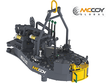
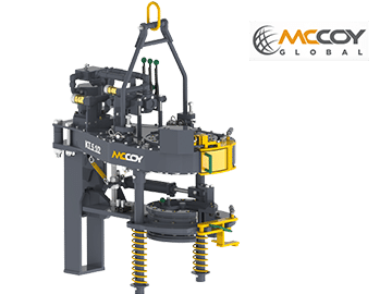
The KT5500 hydraulic power tong can handle tubulars as small as 2-1/16″ and as large as 5-1/2″ in diameter. Wraparound jaw and die technology for the two tong jaws is available. Also available with low-marking CHROMEMASTER™ “softgrip” jaw assembly mated to a 5-1/2″ tong. Tong can be mounted on either a CLINCHER® or FARR® hydraulic backup. Available with McCoy’s patented WinCatt® data acquisition and torque control system for the make-up of tubular connections.

The FARR® KT5500 hydraulic tubing tong can handle tubulars as small as 2-1/16" and as large as 5-1/2" in diameter. Wraparound jaw and die technology for the two tong jaws is available. Also available with low-marking CHROMEMASTER™ "softgrip" jaw assembly mated to a 5-1/2" tong. Tong can be mounted on either a CLINCHER® or FARR® hydraulic backup. Available with McCoy"s patented WinCatt® data acquisition and torque control system for the make-up of tubular connections.

Tongs - Power - BJ sucker rod tong adopts advanced sucker rod or tubing technology and has a compact structure, high reliability and is safe and convenient to operate.
Tongs - Power - New Carter Tool Co. Inc., CT93R Hydraulic powered tubing tong. Complete with 2-3/8" to 3-1/2" jaw assemblies, standard motor, torque gauge assembly, pressure relief valve... More Info
Tongs - Power - New Carter Tool Co., Inc. 5-1/2" CTSX Hydraulic Tubing Tong with heavy case and cover; complete with rigid hanger assy., suspension spring assy., front end control assy.,... More Info
Tongs - Power - New Carter Tool Co. Inc. M-Series power sucker rod tongs, complete with spring hanger assy., gate assy., front end control assy., pressure gauge assy., two 90 degree XH s... More Info
Tongs - Power - New Carter Tool Co., Inc. 4-1/2" RSX Hydraulic Tubing Tong with heavy case and cover; complete with rigid hanger assy., suspension spring assy., front end control assy., ... More Info
Tongs - Power - D D 58-93-2-R Power Tubing Tong is smaller, lighter, and faster than the Foster 5893R. The D D 58-93-2-R Tong is capable of gripping tubulars from 1 5/16" to 7" o.d. More Info
Tongs - Power - FARR TONG MODEL KT 14,000 RINEER GA37 MOTOR, LIFT VALVE ASSEMBLY TORQUE CAPACITY: 50,000 FT/LB SIZE RANGE 4 1.2-14 WITH SAFETY DOOR MOST SIZES OF FARR POWER TONGS ARE IN ... More Info
Tongs - Power - FARR TONG MODEL KT20,000 STAFFA 080 MOTOR, LIFT VALVE ASSEMBLY TORQUE CAPACITY: 50,000 FT/LB SIZE RANGE: 7-20 MOST SIZES OF FARR POWER TONGS ARE IN HOUSTON, IN STOCK READ... More Info
Tongs - Power - FARR MODEL KT5500 HYDRAULIC TUBING TONG C/W 2 SPEED RINEER MOTOR, SIZE RANGE: 2-3/8 IN. - 5-1/2 IN. OD, TORQUE RTED: 18,700 FT/LB C/W SAFETY DOOR MOST SIZES OF FARR POWER... More Info
Tongs - Power - FARR TONG MODEL KT5500 TORQUE CAPACITY: 18000 FT/LB SIZE RANGE: 2 1/16-5 1/2 OD WITH SAFETY DOOR MOST SIZES OF FARR POWER TONGS ARE IN HOUSTON, IN STOCK READY FOR IMMEDIA... More Info
Tongs - Power - FARR TONG MODEL KT5500 5 1/2 IN. TONG TORQUE CAPACITY: 18,000 FT/LB SIZE RANGE: 2 1/16-5 1/2 IN. OD, RINEER 15-13 MOTOR, HIGH TORQUE CLINCHER BACKUP TRIPLE VALVE ASSEMBLY... More Info
Tongs - Power - FARR TONG MODEL KT7585 TORQUE CAPACITY: 25000 FT/LB SIZE RANGE: 2 1/16-8 5/8 OD WITH SAFETY DOOR MOST SIZES OF FARR POWER TONGS ARE IN HOUSTON, IN STOCK READY FOR IMMEDIA... More Info
Tongs - Power - FARR TONG MODEL KT7585 8 5/8 IN. TONG TORQUE CAPACITY 25,000 FT/LB SIZE RANGE: 2 1/16-8 5/8 IN. OD, RINEER 15-15 MOTOR CLINCHER BACKUP, TRIPLE VALVE MOST SIZES OF FARR PO... More Info
Tongs - Power - FARR TONG MODEL LW9625 TORQUE CAPACITY 12000 FT/LB SIZE RANGE 2 7/8 -9 5/8 OD WITH SAFETY DOOR MOST SIZES OF FARR POWER TONGS ARE IN HOUSTON, IN STOCK READY FOR IMMEDIATE... More Info
Tongs - Power - Farrs newest tubular connection tool offers a significantly reduced rig footprint, while continuing to deliver power & uncompromising reliability. The simple design drast... More Info
Tongs - Power - Farr Canada"s newest tubular connection tool offers a significantly reduced rig footprint, while continuing to deliver power and uncompromising reliability. The simple de... More Info

Tongs - Power - Farr KT5500 Tubing Power Tongs w/Jaw Die Power Tongs, 5-1/2" available with or without back-ups. KT5500 18K Tongs with hydraulic Clincher Back-up TORQUE TABLE Pressure H... More Info
Tongs - Power - McCoy KT8625 8-5/8" Casing Tong - 25K Tong Power Tongs - (Our KT7585 Model Is Being Rebadged as KT8625. There Have Been No Design Changes to this Tong, It Still Function... More Info
** These are ideal values. Actual achieved torque is highly dependent upon tong efficiency, final position of rotary gear when full torque load is reached, and the motor with which the tong is equipped.

KT5500 5- ” T & CLInCHER® B aCKup This manual covers the following models: DESCRIpTIon oVERaLL Tong BaCKup MoDEL MoDEL MoDEL 5-1/2”configuredpowertong&low-profilecompressionloadcell-style CLINCHER®backup.Tongequippedwithhydraulicmotorcontrol,lift 80-0420-16 80-0420-3 85-0408 control,backupcontrol,rigidsling,&andsafetydoorsystem. 5-1/2” configured power tong & tension load cell-style CLINCHER® backup.Tongequippedwithhydraulicmotorcontrol,liftcontrol,backup 80-0421-3 80-0420-3 85-0506 control,rigidsling,&andsafetydoorsystem.
KT5500 5- ” T & CLInCHER® B aCKup WARNINGS A “LOAD-BEARING DEVICE” IS A CHAIN SLING, RIGID SLING, SPREADER BAR ASSEMBLY, FRAME, OR ANY OTHER DEVICE THAT BEARS THE PARTIAL OR TOTAL WEIGHT OF THE EQUIPMENT FOR WHICH THIS MANUAL HAS BEEN PRODUCED THE LOAD-BEARING DEVICE SUPPLIED BY MCCOY DRILLING &...
The information presented in this document will provide setup, operating, and maintenance instruc- tions for your KT5500 tong & CLINCHER® backup. Due to the wide variety of operating conditions, these instructions must be considered guidelines rather than absolute operating procedures. It is the responsibility of the user to use these guidelines together with an experienced manager to develop operating procedures that conform to all policies set forth by the operating authority (ies).
KT5500 5- ” T & CLInCHER® B nTRoDuCTIon aCKup CongratulationsonthepurchaseofyourFARR®KT-55005-1/2”tongandCLINCHER®backup.Thisunitwillprovide youwithyearsofoutstandingperformance.Simplemaintenanceandcarewillextenditslifeandensureyearsofexcellent performanceandreliability.Thesetup,operating,andmaintenanceinstructionsinthismanualwillassistyouingivingyour equipmentthecareitrequires.Pleasecarefullyreadthemanualbeforeinstallingandusingyourequipment.Replace- mentpartsarereadilyavailablefromMcCoyDrilling&Completions|FARRinEdmontonAlberta.Notethatmanyparts aretransferablebetweenFARR®tongsandbackups.Shouldyouneedreplacementparts,orshouldyouexperienceany difficultynotcoveredinthismanual,pleasecontact: McCoy Drilling & Completions | FARR 14755121AAvenue Edmonton,Alberta CanadaT5L2T2 Phone:780.453.3277 Fax:780.455.2432 SalesFax:780.481.9246 EmailEngineering:engFarr@mccoyglobal.com EmailSales:salesFarr@mccoyglobal.com CustomerCare:customerCareFarr@mccoyglobal.com Website:http://www.mccoyglobal.com/index.php/drilling-completions Model80-0421-3Shown ECHnICaL anuaL ECTIon onTEnTS...
KT5500 5- ” T & CLInCHER® B pECIfICaTIonS aCKup Torque Table ** pressure high gear low gear psi / Mpa lbs.-ft. lbs.-ft. 1000 / 6.89 1530 2074 7650 10372 1400 / 9.66 2250 3050 11250 15253 1800 / 12.41 2970...
KT5500 5- ” T & CLInCHER® B aCKup pECIfICaTIonS Use an EP synthetic grease that meets or exceeds the following specifications: Thickener LithiumComplex NLGIconsistencygrade 2 NLGIperformancegrade GC-LB Penetration-ASTMD217(25°C[77°F] 265-295minimum0.1mm)worked60strokes Droppingpoint,°F[°C]-ASTMD2265 550[288]minimum Hightemperaturelife,hours-ASTMD3527 160minimum Oxidationstability,psi-ASTMD942 (100hr/300hr)0/3 Waterwashout,percent-ASTMD1264 1.8max Rustandcorrosion-ASTMD1743 pass Oilseparation,percentloss-ASTMD1742 1.1max(24hours,25°C[77°F] Leakage,glost-ASTMD4290 1.0max...
KT5500 5- ” T & CLInCHER® B & o aCKup ETup pERaTIon Inspection Of Slings McCoy Drilling & Completions strongly recommends the following practices: Acompleteinspectionofnewload-bearingdevicesandattachmentsshallbeperformedbyaqualified,designatedpersonprior toinitialuse.Eachlinkandcomponentshallbeexaminedindividually,takingcaretoexposeandexamineallsurfacesincluding theinnerlinksurface.Theslingshallbeexaminedforconditionssuchasthoselistedintheremovalcriteriabelow.Inaddition, dailyinspectionofslings,fasteningsandattachmentsshallbeperformedbyadesignatedperson.Ifdamageordefectsarefound ateitherinspection,thedamagedordefectivecomponentshallbequarantinedfromserviceuntilitcanbeproperlyrepairedor replaced. RemovalCriteria: Aload-bearingdeviceshallberemovedfromserviceifconditionssuchasthefollowingarepresent: • Missingorillegibleslingidentification. • Cracksorbreaks • Evidenceoftamperingisseen-slingtaghasbeenmodifiedorobscured,ortamper-proofnutsaremissing. • Signsofimpactonload-bearingcomponents,includingspreaderbars,liftinglugs,rigidslings&rigidslingweldments,and legs&legmounts.
& o KT5500 5- ” T & CLInCHER® B ETup pERaTIon aCKup Item Description RigidSlingLevelingDevice CagePlateAssembly SafetyDoorSwitchGuard SafetyDoorSwitch TongDoorLatch TorqueGaugeMountingPlate BackingPinAssembly TongJawswithDieInserts BrakeBandAdjustment TongDoorCylinder TongDoorWeldment ECHnICaL anuaL ECTIon onTEnTS...
KT5500 5- ” T & CLInCHER® B & o aCKup ETup pERaTIon Item Description HydraulicValveBankAssembly ManualShiftAssembly AccessPanel CLINCHER®CylinderWithWraparoundInsert HydraulicMotor MotorMount TensionLoadCell ECTIon onTEnTS ECHnICaL anuaL...
& o KT5500 5- ” T & CLInCHER® B ETup pERaTIon aCKup Item Description CLINCHER®Backup-CompressionLoadCellConfiguration RearLegAssembly-CompressionLoadCellConfiguration CompressionLoadCell ECHnICaL anuaL ECTIon onTEnTS...
The following table lists all jaw die kits that are available as standard stocked sizes for this model of tong. McCoy Drilling & Completions | Farr offers a good selection of standard jaw sizes. However, please note that we can custom-engineer and manufacture any size of jaw within the range of the tong. Jaw systems are available to allow use of die inserts intended for...
KT5500 5- ” T & CLInCHER® B aCKup WRAPAROUND JAW DIE KITS (Inserts Not Included) Description Part Number 2-3/8”-3-1/2”WraparoundJawDieKit 1064-WJK-350 4”-5-1/2”WraparoundJawDieKit 1064-WJK-550 2-3/8”WraparoundInsert(forusein1064-WJK-350) 12-2001 2-7/8”WraparoundInsert(forusein1064-WJK-350) 12-2003 3-1/2”WraparoundInsert(forusein1064-WJK-350) 12-2006 4”WraparoundInsert(forusein1064-WJK-350) 12-2007 4-1/2”WraparoundInsert(forusein1064-WJK-550) 12-2009 5”WraparoundInsert(forusein1064-WJK-550) 12-2011 5-1/2”WraparoundInsert(forusein1064-WJK-550) 12-2012 Jaw / Jaw Die Removal Thetongjawswilloftenrequireremovaltochangejawsizeorreplacewornjawdieinserts.Supportthejawbeingremoved...
KT5500 5- ” T & CLInCHER® B aCKup Jaw / Jaw Die Removal (continued): Backup Jaw Availability Thefollowingtablelistsallinsertsthatareavailableasstandardsizesforthe5-1/2”CLINCHER®backup.Ifyourdesiredsize isnotlisted,Farrcanengineercustomjawsizes-contactsalesforfurtherinformation. 3.75”CLINCHER®BackupInsert 12-6034 Description Part Number 2.375”CLINCHER®BackupInsert 12-6003 3.875”CLINCHER®BackupInsert 12-6118 2.375”CLINCHER®BackupAluminumInsert 12-6120 4”CLINCHER®BackupInsert 12-6043 2.875”CLINCHER®BackupInsert 12-6007 4”CLINCHER®BackupAluminumInsert 12-6130 2.875”CLINCHER®BackupAluminumInsert 12-6113 4.125”CLINCHER®BackupInsert 12-6046 2.875”CLINCHER®BackupInsert(Grit)
& o KT5500 5- ” T & CLInCHER® B ETup pERaTIon aCKup CLINCHER® Backup Jaw Removal/Installation Extend CLINCHER® cylinders enough so that the hex flat-head cap screws securing the die retainer tabs are well exposed.Turnoffhydraulicpower. ii. Removethetwohexflat-headcapscrewssecuringthedieretainertabonthetopoftheCLINCHER®die. iii. Removethetopdieretainertabs. iv. Slidethediestraightup,andremove.
& o KT5500 5- ” T & CLInCHER® B ETup pERaTIon aCKup Suspension & Restraint (continued): McCoyDrilling&Completionsrecommendsusingdualbackup(snub)linesofsufficientstrengthtowithstandtheforceimparted bythemaximumratedtorqueofthetongandbackupassemblyinuse.Thesnublineswillarrestuncontrolledmovementofthe tongandbackupintheeventslippingofthebackupjaws.Calculatetheforceonthesnublinesbydividingthemaximumtorque ofthetongbythetong’storquearm(expressedinfeet).Forexample,a25,000lbs.-ft.tongwitha32inch(2.667ft.)torque armwillgenerate9375lbs.offorceagainstthesnubline.Selectyoursnublinesbaseduponthetotalforceandthemarginsof safetydictatedbythepoliciesofyourcompanyandbyestablishedengineeringpractices.Ultimately,calculatingtheforceon thesnublineandselectionofthesnublineisthecompleteresponsibilityofthecustomer. Snublinesmustbesecurelyconnectedtotherearofthetongandbackupassembly,andtiedofftoasuitableanchor. MCCOY DRILLING & COMPLETIONS ACCEPTS NO RESPONSIBILITY FOR DESIGNING AND SELECTING AN ADEQUATE SUSPENSION AND RESTRAINT SYSTEM FOR YOUR DRILLING EQUIPMENT ALL SELECTED FASTENERS, SHACKLES, CLAMPS, ETC.
KT5500 5- ” T & CLInCHER® B & o aCKup ETup pERaTIon Tong Leveling Continued: ii. Placealevellengthwise(fronttoback)alongthetong,ensuringthatitisparallelwiththesurfaceofthetong.Loosenthe 3/4”jamnutsontheadjustingboltsonrigidslingbrackets.Completelyloosentheadjustingbolts.Turneachadjusting boltequallyuntiltonghangslevelfront-to-back.Lockadjustingboltsinplacewiththejamnuts. Loosen 3/4” hex jam nut be- fore rotating adjustment bolt Compression Load Cell Configuration Thebackupisdirectlycoupledtothecompressionloadcellviathebackupbodypaddle.Theloadcellhangerissimplyhung onthepaddleandsecuredthroughthetopofthe“U”byaboltandwasherset,andinnormaloperationdoesnotneedtobe adjustedorremoved.Theassemblyinthefirstofthefollowingtwoillustrationshasbeenconfiguredinthe“make-up”configura- tion;toconverttheassemblytothe“break-out”configurationremovetheboltandwashersetsecuringtheloadcellholdertothe paddle,andmovetheentireassemblytotheothersideofthepaddle. Load cell configured for make-up operations 2.18...
& o KT5500 5- ” T & CLInCHER® B ETup pERaTIon aCKup Compression Load Cell Configuration (continued): Load cell configured for break-out operations Tension Load Cell Configuration Thebackupiscoupledtotherearlegoftheassemblywithatensionloadcellononeside,andarestraintchainontheother. To change the torque measurement configuration (make up to break out or visa versa) simply remove the heavy duty bolts securingtheloadcellandrestraintchains,andswitchtotheoppositesides.Reinstalltheheavydutyboltstosecuretheload...
KT5500 5- ” T & CLInCHER® B & o aCKup ETup pERaTIon Valve Operation 4-wayproportionalvalvescontroloperationofhydraulicdevicesonthetongassemblysuchashydraulicmotorsandcylinders. Whenanyonevalveis“centered”orinthedetentposition,thereisnohydraulicoutputfromthevalve.Whenthevalveispushed forwardthereisaneffect,andwhenthevalveispulledback,thereisanoppositeeffect.Thesevalvesfeatureproportionalcon- trol,whichmeansthatfurtherextensionofthevalvehandle(therebyfurtheropeningthevalveorifice)resultsinproportionally higherhydraulicoutputtothecontrolleddevice. Thefollowingillustrationdemonstratesthetypeandeffectofthehydraulicvalveswithwhichthistongismaybeequipped. TONG MOTOR Thisisaproportionalvalve.Pushingthevalvehandleforwardwillcausethetongmotortorotateinaclockwisedirection(as seenfromthetopofthetong).Thisisthedesireddirectionofrotationformakingupajoint.Pullingthevalvehandleinthe oppositedirectionresultsincounter-clockwiserotation,whichisthedesireddirectionofrotationforbreakingoutajoint. BACKUP Dependingonthetypeofbackupwithwhichyoursystemisequipped(Wedge,Clincher,orHydraulic)pushingforwardon thisvalvewillextendthebackupcylinder(s),oractuateasequencevalve.Pullingbackward,towardstheoperator,reverses theaction. 2.22 ECTIon onTEnTS ECHnICaL anuaL...
& o KT5500 5- ” T & CLInCHER® B ETup pERaTIon aCKup LIFT CYLINDER Thisisadirect-actingvalve.Pushingthevalvehandleforwardwillcausetheliftcylindertoliftthetongvertically.Pullingthe valvehandleintheoppositedirectionwillcausetheliftcylindertolowerthetong. SHIFTING GEARS Theshiftingshafthasthree“detent”positionsidentifyingthelowspeed/hightorqueposition,the“neutral”orfree-spinningposi- tion,andthehighspeed/lowtorqueposition.Thedetentstrengthmaybeadjustedbyreleasingthelocknutonthedetenttube andincreasingorrelaxingpressureonthedetentspring.Ensurethelocknutistightenedoncethedesireddetentpressurehas beenset. Toshifttothehigh-speedgear,movetheshiftinghandleupwardfromneutralposition.Toshifttothelow-speedgear,move theshiftinghandledownthroughtheneutraldetenttoitslowestposition.Notethatthehighclutchgearorthelowclutchgear maynotbeexactlyalignedwhenshifting,sotheoperatormayneedto“bump”themotorcontrolhandleslightlytoturnthemain clutchgearshaftandshiftingcollarintoalignment.Thisismosteffectivewhenapplyingasmallamountofpressureonthegear shiftleverinthedirectionyouwanttoshiftthetong,ensuringtheshiftingcollarwill“catch”whenthemainclutchgearaligns witheitherthehighorlowclutchgear. SHIFTING TONG WHILE ROTATING THE MOTOR AND CAGE PLATE MAY RESULT IN CATASTROPHIC GEAR TRAIN FAILURE 2.23...
KT5500 5- ” T & CLInCHER® B aCKup aInTEnanCE Pinion Applygreasetothepinionbearingsthroughthegreasefittingslocatedonthebearingcapsonthetopandbottomfacesofthe tong(twolocationstop,twolocationsbottom). Clutch Bearings Applygreasetotheclutchbearingsthroughthetwogreasefittingslocatedontheclutchbearingcaponthebottomfaceofthe tong,andthesinglegreasefittingrecessedintotheendoftheclutchshaft.(threelocationstotal). ECTIon onTEnTS ECHnICaL anuaL...
KT5500 5- ” T & CLInCHER® B aInTEnanCE aCKup Motor Mount Applygreasetothemotorgear/clutchdrivegearthroughthegreasefittinglocatedonthetopofthemotormount(onelocation only). Shifting Shaft Applygreasetotheshiftingshaftandtopshiftingshaftbushing.Theshaftandshiftingyokecanbeaccessedthroughthecover plateonthesideofthetong. Access shifter components through this panel ECHnICaL anuaL ECTIon onTEnTS...
KT5500 5- ” T & CLInCHER® B aCKup aInTEnanCE Door Latch Applygreasetothedoorlatchthroughthegreasefittinglocatedinthetopoftheadjustmentcam. 10. CLINCHER® Cylinders Applygreasetotheexternalsurfacesoftheclinchercylindersthroughthegreasefittingsinthetopandbottombodyplates (eightlocationstotal). ECTIon onTEnTS ECHnICaL anuaL...
KT5500 5- ” T & CLInCHER® B aCKup aInTEnanCE Door Latch Adjustment Normaloperationofthetongmaycausewearofthedoorlatch,whichwillcausethedoortodevelopaloosefitatthelatch.A latchcamplateislocatedatthetopfaceofthedoor.Thecamplatehaseightpositioningholeslocatedona360degreebolt circle.Thelatchcamshaftextendsdownthroughthedoorandissecuredatthetopbya3/8”hexheadbolt.Tomakeadjust- mentsindooralignment,removethe3/8”boltandturnthecamwithawrench.Whenthedoorhasbeenadequatelyaligned, replacethe3/8”bolt(seeillustrationnextpage). THE DOOR IS AN IMPORTANT PART OF THE STRUCTURAL INTEGRITY OF THE TONG. IT IS IMPERATIVE TO KEEP A SECURE FIT AT THE DOOR IN ORDER TO MAINTAIN PROPER GEAR ALIGNMENT, AND TO MINIMIZE THE POSSIBILITY OF DAMAGE TO THE GEAR TRAIN WHEN OPERATING THE TONG AT SPECIFIED TORQUE.
KT5500 5- ” T & CLInCHER® B aCKup aInTEnanCE 14. Removedoorassemblybyremovingthedoorrollershaft.Supportdoorassemblyastherollershaftisremoved.Removethe nutfromthetopoftherollershaft,anduseasoftalloymaterial(e.g.brassrod,etc.)tolightlytaptheshaftdownthroughthe supportrollerassemblyuntilitcomesfreeatthebottom.Usecautionthatthethreadsontheendsofthesupportrollershafts arenotdamaged.Donotlosethedoorshoulderbushings. 15. Removethehitchpinsecuringthetorquegaugeholdertothetorquegaugemountweldment,andremovethemount. 16. Removethefourhexsocketheadcapscrewssecuringthemotorandthetorquegaugemountweldment.Removethetorque gaugemountweldment,thenliftthemotorupandawayfromthemotormount.Inspectthemotorgear,locatedatthebottomof themotorshaft,forgearclashingortoothdamage.Also,ensurethatthemotorgearissecurelyattachedtothemotorshaft. 17. Removethecotterpinandclevispinconnectingtheshifterhandletotheshiftershaft(itisnotnecessarytodisconnectthehandle fromthepivotlugweldment). 18. Unboltthepivotlugweldmentfromthetopplate,andremovethepivotlugandhandleassembly. 19. Removethefourhexsocketheadcapscrewssecuringthemotormounttothetopplate.Usecarenottodislodgeandlosethe twopositioningdowels. 20. Removethesnapringsecuringthedrivegeartothetopoftheclutchshaft.Carefullyremovethedrivegearfromtheclutchshaft. 21. Removethetwo10-24x3/4”hexsocketheadcapscrewssecuringthetopclutchbearingretainertothetopplate. 22. Removethetopclutchbearingretainer,andbearingretainerspacer.Thetopclutchbearingandclutchbearingbushingmay comeoffwiththebearingretainer. 23. Pull the top bearing cap and spacer for the pinion drive gear by removing the four 1/2” bolts which secure the bearing cap.
KT5500 5- ” T & CLInCHER® B aCKup aInTEnanCE NOTE ON INSTALLATION PRACTICES: Ensure all bearings are liberally greased before installing over a shaft or into gears or bearing caps. When inserting a shaft through a support roller assembly ensure shaft is greased. Also ensure all metal-to-metal contact in the gear train is adequately greased.
KT5500 5- ” T & CLInCHER® B aCKup Mechanical Assembly Procedure (Continued): 27. Securethetopplatewithfourteen3/8”UNCx1-1/2”hexboltsand3/8”lockwashers,andfive3/8”UNCx1”low-headheight hexsocketheadcapscrews.Donotinstallfastenerscoincidentalwiththerigidslingbrackets(showncircledingreen)orthe doorcylinderpost(showncircledinred). 28. Slidetheclutchbearingretainerspacer(PN1400-59A)overthebottomofthetopclutchbearingretainer(PN997-D11-59),and mounttopclutchbearingretainerandspacertothetopplatewithtwo#10-24x3/4”hexsocketheadcapscrews. 29. Presstopclutchbearing(PN02-0002)intotopclutchbearingretainer.Insertclutchbearingbushing(PN997-60)shoulderside upbetweenbearingandclutchshaft. 30. Secureclutchdrivegear(PN997-A3-61)tothetopoftheclutchshaftwithretainingsnapring(PN02-0001). 31. Installrotaryidlerpads(PN997-D20-125)overthetopoftherotaryidlershaftsandsecurewith1-1/2”UNFhexnylocknuts. 32. Pressremainingpinionbearingintothetoppinionbearingcap(PN997-D15-89)andsecureoverthetopofthepiniongearshaft withfour1/2”UNCx1-1/4”hexboltsand1/2”lockwashers. 33. Slidethetopshifterbushing(PN101-0020)overtheshiftingshaftandthreadintothetopplateuntilsnug. 34. Threadthedetenttube(PN101-0019)intothetopshifterbushingasshown.Threadthree5/8”NCx5/8”hexsocketsetscrews intotheremainingthreeportsinthetopshifterbushing-donotbottomoutthesetscrewsontheshiftingshaft,ortheshaftwill notmove. 3.14 ECTIon onTEnTS ECHnICaL anuaL...
KT5500 5- ” T & CLInCHER® B aCKup Mechanical Assembly Procedure (Continued): 35. Insertthedetentball(PN02-0018)throughtheendofthedetenttubeattachedtothetopshifterbushing,followedbythedetent spring(PN997-0-64)Threada7/16”UNFjamnutontoa7/16”UNFx1-1/4”hexbolt,andthenthreadtheendoftheboltinto thedetenttubeonthetopshifterbushing. 36. Inserttwo5/16”x3/4”productiongrounddowelpinsintothetopplate,oneoneithersideofthemotorshaftandgearcut-out, directlybehindtheclutchassembly. 37. Positionthemotormount(PN1400-150)overthedowelpinsandsecuretothetopplateusingfour1/2”UNCx2”hexsocket headcapscrews. 38. Inserta5/16”x5/16”x1-1/2”squarekeyintothekeyslotonthemotorshaft.Securethemotorgear(PN997-A10-149)tothe hydraulicmotorshaftusingtwo3/8”UNCx3/8”flatpointhexsocketsetscrews.Ensurethatthemotorgearisorientedsothat themachinedendofthemotorgear(theendinwhichthesetscrewsarethreaded)isflushwiththeendofthemotorshaft. 39. Mounthydraulicmotor(PN87-0110)tomotormount.SecuretheRHsideofthemotor(asseenfromthebackofthetong)with two1/2”UNCx1-1/4”hexsocketheadcapscrewsand1/2”lockwashers.Thetorquegaugeholderweldment(PN1500-09-04A) issecuredbythetwoLHmotorscrews-positionthetorquegaugeholderweldmentinplace,andsecureitandtheLHsideof themotorwithtwo1/2”UNCx1-1/2”hexsocketheadcapscrewsand1/2”lockwashers. 40. Attachthetwo#20(1-1/4”)xJIC1”flangeelbows(PN02-9216)tothemotorportsusingtwo#20splitflangekits(PN02-9217). 41. Attachtheshifterlugweldment(PN101-0016)tothetopplateofthetongnexttothetopshifterbushingweldmentusingfour 3/8”UNCx1-1/4”hexboltsand3/8”lockwashers. 42. Connecttheshifterhandleweldment’s(PN1037-D-20B)pivotpointtothepivotpointoftheshifterlugweldmentusinga5/16” x1-1/2”clevispin.Connecttheendoftheshifterhandleweldmenttothetopoftheshiftershaftusinga5/16”x1”clevispin. Securetheclevispinswith.093”X1.125”hitchpins.
KT5500 5- ” T & CLInCHER® B aCKup aInTEnanCE Mechanical Assembly Procedure (Continued): 44. Installtheremainingsupportrollershafts(excludingthedoorpivotrollershaft): “Stand-Alone”Tongs(Models80-0420-5,80-0420-12) Slidea7/8”narrowflatwasherovertheremainingfivesupportrollershafts(PN101-3942)andinsertintotheremaining supportrollerassemblies(excludingthedoorpivotsupportroller). ii. Secure the bottoms of the support roller shafts with 7/8” narrow flat washers and 7/8” UNF thin nylock nuts with the exceptionofthetwoshaftsdirectlybehindthebrakebandlugweldments.Thesetwoshaftswillserveaslegmountsin...
KT5500 5- ” T & CLInCHER® B aInTEnanCE aCKup Mechanical Assembly Procedure (Continued): 55. Attachthedoorlatchweldment(PN1064-C7-15)tothedoorweldment(PN1400-10)usingthedoorlatchcam(PN1400-14) -ensurethatthedoorlatchsprings(PN997-16)areinstalledbetweenthedoorlatchandthedoorweldment.Threadthedoor latchcamintothedoorweldmentuntilinbottomsout,andthenbackitoffuntilthefirstadjustmentholeinthelatchcamaligns withthethreadedholeonthetopofthedoorweldment.Securethelatchcamtothedoorweldmentwitha3/8”UNCx1”hex boltand3/8”lockwasher. 56. Insertthethedoorpivotshoulderbushings(topbushing=PN101-5110,bottombushing=PN101-5111)inthedoorweldment -notethatthebushingsareinstalledfromtheinsidesofthedoorplates. 57. Alignthedoorpivotholeswiththepivotholesinthetopandbottomplatesandinsertthedoorpivotrollershaft(PN101-3943)-it mayhavetobetappedlightlywithasoftmetalorrubberhammer.Usecautionwhenslidingtheshaftthroughthesupportroller components.Oncetheshafthasbeentappedallthewaythrough,securethebottomoftheshaftwitha7/8UNFthinnylock nutand7/8”narrowflatwasher. 58. Ifyourtongisequippedwiththesafetydooroption,itmaynowbeinstalled(SeePp.7.32-7.33)usingthefollowingprocedure: Attachsafetydoorlatchblock,PN101-1103,tosafetydoorlatchplate,PN101-1105,usingthree3/8”NCx7/8”flathead countersunkcapscrews. ii. Placesafetydoorlatchplate,PN101-1105ontothebottomplateofthesafetydoorguardweldment,PN101-1481,and aligntheboltholes.Securetothetopplateusingthree3/8”NCx2-1/4”hexboltsandlockwashers. iii. Attachthesafetydoorlatchblock,PN101-0914,tothetopofthedoorplateusingtwo3/8”NCx1-1/2”hexboltsand lockwashers,andtwo3/8”NCx1-1/2”flatheadcountersunkcapscrews. iv. Attachsafetydoorlatchblock,PN101-1104,tothesafetydoorlatchblockinstalledinstep42(iii)usingfour3/8”NCx 7/8”hexcapscrewsandlockwashers.
KT5500 5- ” T & CLInCHER® B aCKup aInTEnanCE Mechanical Assembly Procedure (Continued): 61. Attachtherigidslinghangerweldments(LHweldment=PN101-0150,RHweldment=PN101-0151)tothetopplateusing two3/8”NCx1-3/4”bolts(outside),two3/8”NCx1”bolts(inside),andfour3/8”lockwashersperhanger. 62. Installinletcouplingsupportassembly(PN1050-C-175)tothetopplate,betweentheRHpinionidlerandRHrotaryidler, usingtwo3/8”NCx1”hexboltsand3/8”lockwashers.Attachtheoutletcouplingsupportbase(PN101-0023)tothetop platerightofthepinionbearingcapusingtwo3/8”NCx1”hexboltsand3/8”lockwashers,andattachtheadjustingplate (PN101-0022)tothesupportbaseusingtwo3/8”NCx1”hexbolts,two3/8”flatwashers,andtwo3/8”UNCnylocknuts. 63. Installtwohydraulicvalvemountweldments(PN101-1442)tothetopplateoneithersideofthebrakebandretainerusing one3/8”NCx1”hexboltand3/8”lockwasherperweldment. 64. Installthehydraulicvalveassemblytothevalvemountweldmentsusingone1/2”NCx4-1/2”hexboltand1/2”narrowflat washerpervalvemount.Installmaininletandoutletlines,andtheremainderofthehydraulicconnections.Seethehydraulic schematicforhydraulicconnections. 65. Slidethemasterliftinglink(PN02-0516)overtheadjustmenthelix(PN1053-1-H),andinstalltheadjustmenthelixintherigid slingweldment(PN101-0112)usinga3/4”UNCx8”hexboltand3/4”UNCnylocknut. 66. Useacranetohoisttherigidslingweldment.Connecttherigidslingweldmenttotherigidslingmountinglugswithrigidsling pins(PN1053-C-1C).Secureeachpinwithtwo0.148”x2.938”hitchpins. 67. Threada3/4”UNChexnutontoeachoftworigidslinglevelingadjustmentweldments(PN1053-C-1L).Threadtheleveling adjustmentweldmentsintothefrontoftherigidslingweldmentmountingbrackets,roughlyadjustingthemsotherigidsling isapproximatelyperpendiculartothetopplateofthetong(seeillustration3.H.10). 68. Thread1/2”UNChexnutsontotwo1/2”UNCx1-3/4”hexbolts.Threadtheboltsintotherearoftherigidslingweldment mountingbrackets.(seefollowingillustration).
KT5500 5- ” T & CLInCHER® B aInTEnanCE aCKup Mechanical Assembly Procedure (Continued): 71. Useacraneandtemporaryslingtohoistthebackupassemblyontoasupportstructurenexttotheassemblylocationofthe tong.Minimumheightforthebackupsupportsmustbe36”inordertoallowclearanceforinstallingthefrontlegs. 72. 80-0420-16 assembly (uses 85-0408 backup) only:installtherearbackupsupportspringassemblyintherearleg(seePp. 5.40-5.41): a. Placetwosprings(PN991-13)overthenubsononeofthetwospringplateweldments(PN101-4495).Placethesecond springplateweldmentoverthespringsandusefour1/2”UNCx6”hexbolts,1/2”narrowflatwashers,and1/2”UNC hexnylocknutstofastentheassemblytogether. Installthespringsupportweldmentintherearlegusingtwo3/8”UNCx9-1/2”hexbolts,3/8”narrowflatwashers,and 3/8”UNChexnylocknuts.Thelocationofthesupportcanbechangedasrequiredwhenlevelingthebackup. 73. 85-0404 and 85-0506 backup assemblies only:ifusingeitherofthesebackupsensuretheyareproperlypreparedformat- ingwiththetongandrearlegassembly.RefertoPp.5.40-5.41. Threada1-1/4”UNCheavyhexnutontothe1-1/4”UNCx8”threadedrod(PN101-1993). Coatatleast2”ofthreadonthethreadedrodwithredLoctite.Screwthethreadedrodintotheheavyhexboltweldedto thetopplateofthebackupuntiltherodbottomsout.Lockthethreadedrodinplaceusingtheheavyhexnutthreaded...
KT5500 5- ” T & CLInCHER® B aCKup aInTEnanCE Mechanical Assembly Procedure (Continued): 83. Attachtheoutletcouplingsupportweldment(PN101-0023)totheweldmentmountusingtwo3/8”NCx1”hexboltsand 3/8”lockwashers.Attachtheadjustmentplate(PN101-0277)totheoutletsupportweldmentusingfour3/8”NCx1”hex bolts,3/8”narrowflatwashers,and3/8”UNChexnylocknuts. 84. Coatthethreadsofthehydraulicvalvemountingposts(PN101-0116)withLoctiteandthreadintothetopplatejustbehind thebrakebandoneithersideofthebrakebandretainer. 85. MounttheDVA35hydraulicvalveassemblyonthemountingpostsusingtwo1/2”UNCx4-1/2”hexboltsand1/2”narrow flatwashers. 3.20 ECTIon onTEnTS ECHnICaL anuaL...
KT5500 5- ” T & CLInCHER® B aCKup aInTEnanCE Performavisualinspectionofallhydrauliclines.Replaceflexiblelinesiftheyappeartobecracked,fatigued,orhave 13. visiblesignsofwearfromcontactwitharigidobject. 14. Performacompletegreasingofthetong-refertoMaintenancesectionofthetechnicalmanual Ensuremainsupplyandreturnconnectionstothetongarefullymadeup.Re-connecttheremainderofthehydraulic 15. lines,and,ifapplicable,theelectricallinetotheturnscounter. FAILURE TO ENSURE THAT THE SELF-SEALING SUPPLY AND RETURN LINES ARE FULLY MADE UP MAY RESULT IN CATASTROPHIC EQUIPMENT FAILURE. Ifusingastand-alonepowerunit,startitnow-refertothepowerunittechnicalmanualforstartupprocedures.Listentopowerunitfor amomenttoseeifthereareanyunusualmechanicalsounds(rubbing,grinding,excessivepumpnoise).Ifusingadieselunit,allow sufficienttimefortheenginetoreachoperatingtemperaturebeforeincreasingengineRPM.Onceengineiswarm,graduallyincrease engineRPMuntiloperatingspeedisreached.
Rotatecageplate/rotarygearuntiltheopeningintherotarygearfacestowardstherearofthetong. DO NOT PERFORM ANY FURTHER ACTIONS OR MAINTENANCE WHILE THE TONG IS CON- NECTED TO ANY HYDRAULIC POWER SUPPLY. FARR RECOMMENDS THAT ALL HYDRAULIC LINES ARE FULLY DISCONNECTED, AND RESIDUAL HYDRAULIC PRESSURE IS BLED OFF. ENSURE ADEQUATE CONTAINMENT IS IN PLACE TO PREVENT ENVIRONMENTAL CONTAMI- NATION FROM RESIDUAL HYDRAULIC FLUID.
” T & CLInCHER® B aCKup aInTEnanCE Performavisualinspectionofallliftingpoints-ifvisibledamageisseen,includingcracks,brokenlugs,distortedmetal, etc.replacedamagedpart(s)beforeplacingtonginservice.Alsoinspectallchains,masterlinks,andturnbuckles- again,ifanydamageisnotedreplacethedamagedpart(s)beforeplacingthetonginservice.RefertoSection2Aof 12. thetechnicalmanual(Sling/LoadBearingDeviceSafety)forinformationonrecommendedtestingandrecertification. Pleasenotethatturnbuckleswithpartnumber101-3086(shortturnbuckles)useahigh-strengthpinwhichmustbe suppliedbyFarr. “SHORT” TURNBUCKLES HAVING PART NUMBER 101-3086 EMPLOY HIGH-STRENGTH PINS WHICH MUST BE SUPPLIED BY FARR. Rotatethegeartrainbyhand,anduseaflashlighttoperformavisualinspectionofthegeartrainthroughtheaccess panelandtheopeningoftherotarygearwhilethegeartrainisbeingrotated.Ifgeardamageorchipsofmetalare 13. seen,thetongshouldberemovedfromserviceandoverhauledtoavoidfurtherdamage.Replaceaccesspanelwhen inspectioniscomplete. Inspectalljawsanddiesinuseforthemaintenanceinterval.Inspectthejawrollerpinsforsignsofdamage-replace 14. pinsifnecessary.Ifthepinsareweldedinplace,removeandquarantinethejawuntiltheweldisrepaired.Ensuredies aresecureinthejaw-replaceworndiesifnecessary.Ensurethatthejawrollersrotatefreely. 15. Inspectbackingpin(s).Ifcracked,broken,orbentit(they)mustbereplaced.
KT5500 5- ” T & CLInCHER® B aInTEnanCE aCKup Re-energizepowerunitandextendallhydrauliccylinders.Inspectcylinderrodsforsignsofmechanicaldamage,flak- 28. ing,orrust.Farrrecommendsthatdamagedcylindersbereplaced. 29. Rotatetonginlowgearfor5minuteswhilemonitoringpressurizedsealsandhydrauliclines.Ifaseal,line,orfitting beginstoleakwhiletongisrotating,itmustbereplacedbeforetheequipmentisreturnedtoservice. Rotatetonginhighgearfor5minuteswhilemonitoringtemperatureoftopandbottombearingcaps.Ifthebearingcaps 30. arehottothetouch(higherthanapproximately50 C)replacetheapplicablebearings.Likewiseifthetongismaking unusualnoisescheckfordamagedbearings(seeMaintenanceManualforallbearinglocations). Installloadcell.Ifusingatensionloadcell,performavisualinspectionandreplaceanycracked,broken,ordistorted 31. componentsincludinglinksandchains.Ifusingacompressionloadcell,replaceanycomponentthathasbeencrushed orotherwisedistortedthroughcompression. Ifapplicable,inspecttheloadcellanchorpins(tensionloadcellonly).Replacetheanchorpinsifcrackingormetal 32. distortionisseen. Ifapplicable,theweldsecuringthesingleloadcellanchortothebridgebarmainplatemustbeinspected(compression loadcellonly).Iftheintegrityoftheweldhasbeencompromised,thetongmustberemovedfromserviceuntiltheweld 33. isrepaired.Theloadcellbeamwillneedtobedisconnectedandremovedsotheweldisvisible.Beforere-installingthe beam,liberallygreasetheanchorpinbeforereinsertingintotheloadcellbeam. Inspectloadcellfordamageorsignsofstress.Checkoillevelinloadcellandfillifnecessary(refertotechnicalmanual 34. Section7orSection8). Whilerotatingthecageplate,ensurethatthejawsproperlycam.Ifthejawsdonotcamproperly,thebrakebands 35. needtobetightened.IncrementallyadjustboththetopandbottombrakebandsEQUALLYuntilpropercamactionis achieved.Refertothemaintenancesectionofthemanualforinstructionsonproperlyadjustingbrakebands. Performafullfunctionaltestofthetongincluding,ifapplicable,backupcomponents,liftcylinder,andfloatframecom- 36.
KT5500 5- ” T & CLInCHER® B aInTEnanCE aCKup Energizepowerunit.Rotatetongforoneminute,stop,andreversethedirectionofrotationforanotherminute,endingwith 13. theopeningoftherotarygearfacingthegeartrain. 14. De-energizethepowerunit,andperformathirdgenerouslubricationofthegeartrain,includingthegearhousing. 15. Energizepowerunit,androtatethetongforafinaltime,oneminuteinonedirection,stop,andreversethedirectionof rotationforanotherminute,thistimeendingwiththerotarygearinthe“openthroat”position. Extendallhydrauliccylinders,andinspectcylinderrodsforsignsofmechanicaldamage,flaking,orrust.Farrrecom- 16. mendsthatdamagedcylindersbereplacedpriortostorage. Ifyouareusingaframe-mountedtool,thetongmustbeloweredontothebackupinordertoremovetheriskofsudden andcatastrophicmovementwhenpressureisremovedfromthefloatcylinders.Coverthetopofthebackupwithprotec- tiveclothtoprotectthepaintonthebackup.Placetwowoodenbeamsacrossthetopofthetong,ensuringthatthebeams 17. haveaminimumsizeof4”x4”xthewidthofthetong.Coverthetopsofthewoodenbeamswithmoreprotectiveclothto preventpaintdamagetothetong.Whenloweringthetongontothebeams,ensurethatthebeamscomeintoflatcontact withthebottomofthetong,awayfrombearingcaps,brakebands,orotherprotrusionsonthebottomofthetong.Ensure thatthetonghangerchainsareloose,butnotdanglingintocontactwiththehangersortopplateofthetong. epressurizAtion roceDure torAge Rotatethetongtothe“openthroat”position. Exerciseeachhydrauliccylinderseveraltimes-openthetongandbackupdoors(ifequipped),retractandextendthe remotebackingpinramp(ifequipped),retractandextendthefloatcylinders.Leaveallcylindersexceptforthedoor cylindersintheirfullyretractedposition.Thegeneralideaistohaveaslittleofthechromecylinderrodsexposedas possible. De-energizethepowerunit. RepeatedlyactuatethetongmotorcontrolvalveleverINBOTHDIRECTIONStodissipateanyresidualpressureinthe valveandmotor. RemovethehydraulicSUPPLYlinefromtheequipment.
KT5500 5- ” T & CLInCHER® B aCKup aInTEnanCE Ifpossible,storeinasealed,climatecontrolledenvironment.Ifisolatedstorageisnotavailable,Farrrecommendsstoringyourwrapped equipmentinasecure,out-of-the-waylocation,usingsilicageldesiccanttoreducethehumiditywithinthewrapping.Asaguideline,use 125g.ofdesiccantforeachcubicmetreofspace,or3.5g.percubicfoot. AlculAtion equireD esiccAnt Calculatethetrappedairvolumebymeasuringtheoutsidedimensionsofthetooltobestored,andtreatthatasthevolume tobestored.Forexample,theexternaldimensionsofaKT2000020”powertongare80.25”x50.5”x28”,whichcalculates toanapproximatevolumeof113500in ,or66ft (1.87m Multiplythecalculatedairvolume,incubicfeet,bytherecommendedamountofdesiccantpercubicfoot.Carryingforth the example used in the previous step, the required desiccant charge would be 3.5 g. x 66 ft , equaling 231 g. Several manufacturersoffersilicageldesiccantinpackagedquantitiesof125gramsperbag,sotwopackagesofdesiccantwould berequired.Pleasekeepinmindthatthisisaguidelineonly-moreorlessdesiccantmayberequiredinextremeenviron-...
KT5500 5- ” T & CLInCHER® B aCKup aInTEnanCE Performafullfunctionaltestoftheequipmentincluding,ifapplicable,backupcomponentsandfloatframecomponents. 20. Reportandcorrectanyhydraulicleaksfromthehydraulicvalvebank,orfromanyhydrauliccylindersthatareused. Ifusingaframe-mountedtongandbackupsystem,raisethetongoffthebeamsthatitisrestingupon.Removethebeams 21. andprotectivecloths-inspectthepaintontopofthebackupandthebottomofthetongtoensureithasnotbeendam- agedbythebeam. Testsafetydoorfeature(ifequipped).Openthetongdoor(s),andattempttorotatethecageplateatlowspeed(lowgear) inbothdirections(makeupandbreakout).Ifcageplatebeginsrotating,thesafetydoormechanismisnotfunctional,and 22. thetongmustberemovedfromserviceuntilthesafetydoormechanismcanberepaired.Ifthesafetydoorisoperating correctly,cageplaterotationwillnotbeinhibitedoncethedoorisclosedandlatched. NEVER OPERATE YOUR EQUIPMENT WITH A BYPASSED OR MALFUNCTIONING SAFETY DOOR Whilerotatingthecageplate,ensurethatthejawsproperlycam.Ifthejawsdonotcamproperly,thebrakebands 23. needtobetightened.IncrementallyadjustboththetopandbottombrakebandsEQUALLYuntilpropercamactionis achieved. 24. Whenallofthepreviousstepsarecompleted,youmayreturnyourre-commissionedequipmenttoservice. 3.32 ECTIon...
KT5500 5- ” T & CLInCHER® B aCKup RouBLESHooTIng TONG WILL NOT DEVELOP SUFFICIENT TORQUE Cont’d: 10. POSSIBLEPROBLEM:Loadcellismeasuringincorrectly. SOLUTION:Incorrectloadcellisbeingused. SOLUTION:Airistrappedintorquemeasuringcircuit(loadcell,hydraulicline,orgauge.Refertotorquemeasurementtrouble- shootinginSection6ofthismanual. SOLUTION:Loadcellhasbeendamaged.Replaceloadcell,orreturntoMcCoyforrepairandre-calibration. 11. POSSIBLEPROBLEM:Incorrectmotorspeedselected. SOLUTION:Maximumtorquecanonlybedevelopedwhenmotorisinthelowestspeed.Ensuremotorisinlowspeed. 12. POSSIBLEPROBLEM:Incorrecttonggearselected. SOLUTION:Maximumtorquecanonlybedevelopedwhentongisinlowgear.Ensuretongisinlowgear. MCCOY DRILLING & COMPLETIONS GUARANTEES CALIBRATION OF A LOAD CELL/TORQUE GAUGE ASSEMBLY FOR A PERIOD OF ONE YEAR. MCCOY DRILLING & COMPLETIONS SUGGESTS THAT THE LOAD CELL/TORQUE GAUGE ASSEMBLY BE RETURNED TO THE FACTORY FOR RE-CALIBRATION ON A YEARLY BASIS.
KT5500 5- ” T & CLInCHER® B uppoRT oLLER aCKup Item Type Description Part Number Part 1/4”UNFStraightGreaseFitting 02-0097 Part 101-3942 SupportRollerShaft Part SupportRollerShaft(BackupReadyTongsOnly) 101-3943 Part DoorPivotRollerShaft 101-3944 Part 09-5123 7/8”NarrowFlatWasher Part SupportRollerSleeve 1064-182 Part TaperedRollerBearing 02-0099 Part SupportRollerShaftSpacer 1064-183 Part...
KT5500 5- ” T & CLInCHER® B oTaRy DLER SSEMBLy aCKup Description PartNumber Item Type Part GreaseFitting,1/8”NPT 02-0005 Part 1-1/2”UNFNylockNut 09-5740 Part RotaryIdlerPad 997-D20-125 Part IdlerBearingSpacer 997-D20-121 Part BearingSeal 02-0010 Part BearingRetainerRing 02-0009 Part IdlerShaft 997-D19-117 Part IdlerBearing 02-0011 Part...
KT5500 5- ” T & CLInCHER® B InIon DLER SSEMBLy aCKup Item Type Description Part Number Part IdlerBearingRetainer 02-0008 Part BearingSeal 02-0010 Part RetainerRing 02-0009 Part IdlerGear 997-A2-119 Part IdlerBearing 02-0011 Part IdlerHalfShaft 997-D17-105 Part PinionIdlerPad 1400-109 Part 5/8”CarbonSteelLockWasher 09-5114 Part 5/8”UNCx2-1/4”HexBolt...
KT5500 5- ” T & CLInCHER® B InIon SSEMBLy aCKup Item Type Description Part Number Part GreaseFitting,1/8”NPTx90Degree 02-0093 Part 1/2”UNCx1-1/4”HexBolt 09-1168 Part 1/2”LockWasher 09-5110 Part PinionBearingCap 997-D15-89 Part PinionBearingSpacer 1400-89A Part PinionIdlerBearing 02-0007 Part LowPinionGear 997-A5-88 Part PinionGear 997-A7-86 Part...
KT5500 5- ” T & CLInCHER® B LuTCH SSEMBLy aCKup Description PartNumber Item Type Part OutsideSnapRing 02-0001 Part DriveShaft/ClutchGear 997-A3-61 Part #10-24x3/4”HexSocketHeadCapScrew 09-0001 Part TopClutchBearingRetainer 997-D11-59 Part TopClutchBearingRetainerSpacer 1400-59A Part ClutchBearingBushing 997-60 Part TopClutchBearing 02-0002 Part LowClutchGear 997-A1-52 Part NeedleBearing...
KT5500 5- ” T & CLInCHER® B HIfTER SSEMBLy aCKup Description PartNumber Item Type Weldment ShifterHandle 1037-D-20B Part 5/16”x1-1/2”ANSI/ASMEB18.8.1ClevisPin 09-0256 Part BS15745/64”x5/8”CotterPin Part ShiftingShaft 1400-71 Part ShifterDetentTube 101-0019 Part ShifterDetentBall 02-0018 Part ShifterDetentSpring 997-0-64 Part 7/16”UNFHexNut 09-5908 Part 7/16”UNFx1-1/4”HexBolt 09-1608...
KT5500 5- ” T & CLInCHER® B agEpLaTE SSEMBLy aCKup Description PartNumber Item Type Part 1/2”UNCx8”HexBolt 09-1198 Part 1/2”NarrowFlatWasher 09-5119 Part BackingPinSpacer 101-4093 Part JawPivotBolt 1064-28 Part 1/2”NCx6”HexBolt 09-1190 Part TopCagePlate 1400-21 Part CagePlateSpacer 1064-38 Assembly JawAssembly(5-1/2”shown-seePp.2.12) Part RotaryGear 1064-D1...
KT5500 5- ” T & CLInCHER® B RaKEBanD SSEMBLy aCKup Item Type Description Part Number Part 3/8”NCx3/4”HexBolt 09-1044 Part 3/8”CarbonSteelLockWasher 09-5106 Part BrakeBandRetainer 101-0140 Assembly BrakeBand,Lined 1064-D4-29 Part 3/8”NFHexNut 09-5906 Weldment LHBrakeBandLugWeldment 101-0134 Weldment RHBrakeBandLugWeldment 101-0132 Part 3/8”NFx1-1/2”BrakeBandAdjustmentBolt 09-1553 5.21...
KT5500 5- ” T & CLInCHER® B oToR ounT SSEMBLy aCKup Item Type Description Part Number Weldment TorqueGaugeMountWeldment 1500-09-03A Part 1/2”NCx1-1/4”HexSocketHeadCapScrew 09-2168 Part 1/2”NCx1”HexSocketHeadCapScrew 09-2166 Part 1/2”LockWasher 09-5110 Part RineerGA15-13HydraulicMotor 87-0110 Part RineerGA15-13/6.5Two-SpeedHydraulicMotor(Optional) 87-0007 Part MotorGear 997-A10-149 Part 3/8”NCx3/8”HexSocketSetScrew 09-0106 Part 1/2”NCx1-1/2”HexSocketHeadCapScrew...
KT5500 5- ” T & CLInCHER® B yDRauLIC SSEMBLy aCKup Item Type Description Part Number Part M-NPT/F-NPT90d1”Fitting 02-9221 Part 1”LongNipple 101-0079 Assembly M-ORB/F-NPT90d1”Fitting(Includesseals) 02-9206 Part HydraulicInlet,DVA35-A880 10-9016 Part Male1”QuickCouplerFitting 02-9214 Part 1”DustCap 02-9213 Assembly 1”HydraulicConnectionHoseAssembly 08-1724 Assembly M-ORB/JICLONG90d1”(Includesseals) 02-9210 Assembly...
KT5500 5- ” T & CLInCHER® B SSEMBLy aCKup Item Type Description Part Number Part 5/16”x3/4”UNCShoulderBolt 09-0227 Assembly DoorCylinder 101-0069 Part 3/8”NCx1”HexBolt 09-1046 Part 3/8”CarbonSteelLockWasher 09-5106 Part AdjustmentCam 1400-14 Weldment DoorWeldment 1400-10 Part 3/8”UNCHexNut 09-5806 Part 3/8”NCx1-1/2”HexBolt 09-1553 Part LatchSpring...
KT5500 5- ” T & CLInCHER® B afETy SSEMBLy aCKup Description PartNumber Item Type Part 3/8”NCx3/4”HexBolt 09-1044 Part SwitchGuardTopPlate 101-1480 Part 3/8”NCx2-1/4”HexBolt 09-1055 Part 3/8”CarbonSteelLockWasher 09-5106 Part SafetyDoorLatchBlock 101-1104 Part 15/16”ValveLockNut 09-0278 Part SafetyDoorLatchBlock 101-1103 Part SafetyDoorLatchPlate 101-1105 Part 3/8”NCx1-1/2”HexBolt...
KT5500 5- ” T & CLInCHER® B SSEMBLIES aCKup Item Type Description Part Number Part 1-1/4”NCx8”HexBolt 09-0222 Part 1”NCx7”HexBolt 09-9165 Weldment RearLegWeldment-TensionLoadCellConfiguration 1010-1987 Weldment RearLegWeldment-CompressionLoadCellConfiguration 1010-1547 Part 1-1/4”NCHexNylockNut 09-1484 Part 1”NCHexNylockNut 09-5725 Part 3/8”CarbonSteelLockwasher(Leg-Body) 09-5106 Part 3/8”NCx2-1/4”HexBolt(Leg-Body) 09-1055 Part 3/8”NCx1-1/2”HexSHCS(RearLeg-Body)
KT5500 5- ” T & CLInCHER® B SSEMBLIES aCKup Item Type Description Part Number Weldment LHFrontLegMount 101-0787 Part 7/16”NCx31/2”HexBolt Part 7/8”NFThinNylockNut 09-5722 Part SupportLeg 1364-909 Part FrontLegSpringTopCap 101-4489 Part FrontLegSpring 1302-905-08 Part BottomLegCap 1302-905-03A Assembly SupportRollerShaft 101-3944 Weldment 2”LoadCellHolder 01-9116D Part 1/2”NCx6”HexBolt...
LC C KT5500 5- ” T & CLInCHER® B aCKup SSEMBLy oMpRESSIon onfIg aCKup Item Type Description Part Number Weldment LoadCellHolderWeldment 01-9116D Part 3/8”RegularFlatWasher 09-5006 Part 3/8”NCx1-1/4”HexBolt 09-1048 Part 1-1/4”NCHexNut 09-5832 Part SuspensionSpringV-Bracket 1483-500-00-04 Part SuspensionSpringRetainer 1483-500-00-4B Part 1-1/4”NCx8”ThreadedRod 101-1993 Part 1/4”NCx3/4”HexBolt...
KT5500 5- ” T & CLInCHER® B aCKup RofILE aCKup SSEMBLy LC C oMpRESSIon onfIg Item Type Description Part Number Weldment BackupBody 1421-500-LP Weldment 2”LoadCellHolder 01-9116D Part ReliefValveBody 08-1839 Part BCJBody 08-1327 Part RearCoverPlate 101-4482 Part 3/8”NCx3/4”HexBolt 09-1044 Part 3/8”LockWasher...
CLInCHER® C KT5500 5- ” T & CLInCHER® B yLInDERS aCKup Item Type Description Part Number Part 3/8”UNFx1”HexSocketFlatHeadCapScrew 09-4046 Part DieRetainer(Top) 101-2981 Part DieRetainer(Bottom) 101-2290 Part WraparoundInsert(SeePp.2.14) Part CylinderHousing 1403-01 Part CylinderRod 1401-04B Part CylinderPiston 1401-05B Part 3/8”UNCx1”HexBolt 09-1170 Part 3/8”CarbonSteelLockWasher...
KT5500 5- ” T & CLInCHER® B IgID LIng SSEMBLy aCKup Item Type Description Part Number Assembly ChainSlingAssembly 101-2211 Part 3/4”NCHexNut 09-5818 Part LiftLink 02-0516 Part AdjustingHelix 1053-1-H Part 3/4”NCx9”HexBolt 09-1322 Weldment RigidSlingWeldment 101-0656 Weldment LevelingBolt 1053-C-1L Part RigidSlingPin 1053-C-1C Part 3/8”NCx1”HexBolt...
KT5500 5- ” T & CLInCHER® B oRquE EaSuREMEnT aCKup BASIC TORQUE MEASUREMENT Basictorquemeasurementsareperformedusingasimplehydraulicmeasurementsystem.Ahydraulicloadcellconnectstoacali- bratedtorquegaugethroughareinforcedflexiblehydraulichose.Thetorquegaugeisfactory-calibratedtodisplayaccuratetorque measurementsforatongortongandbackupassemblywithaparticulararmlength.Thearmlengthisameasurementfromthecentre ofthepipeorcasingtothecentreoftheforcebeingappliedtotheloadcell. Twoloadcelloptionsareavailable.Atensionloadcellistypicallyusedwithasuspendedstand-alonetong.Thisapplicationrequires that the load cell be attached to the rear of the tong as part of the restraint line that opposes the force generated when the tong makesuporbreaksoutajoint.Acompressionloadcellisusedinatongandbackupassembly,andistypicallylocatedontherearof...
KT5500 5- ” T & CLInCHER® B aCKup oRquE EaSuREMEnT BASIC TORQUE MEASUREMENT (Continued:) Theimagesontheprecedingpageareforillustrationpurposesonlyandmaynotaccuratelyrepresentthetorquegaugeandloadcell thathavebeensuppliedwithyourequipment.Pleasenotethatthepartslistedinthefollowingtablearecorrectforaccuratetorque measurementwhileusingtheequipmentforwhichthismanualissupplied. THE TORQUE GAUGE USED IS FULLY DEPENDANT UPON THE ARM LENGTH AND TORQUE RANGE OF THE EQUIPMENT IN USE. THE PART NUMBERS LISTED IN THE FOLLOWING TABLES ARE CORRECT FOR ACCURATELY MEASURING TORQUE USING THE EQUIPMENT FOR WHICH THIS MANUAL IS SUPPLIED.
KT5500 5- ” T & CLInCHER® B oRquE EaSuREMEnT aCKup Item Type Description Part Number Assembly StandardTurnCounterEncoderMount 60-0001 Part 6-32x3/8”HexSocketHeadSetScrew Part HelicalFlexibleEncoderShaftCoupling 60-0130N Part InternalRetainerRing 1376-13 Part Bearing 1376-05 Part EncoderHousing 1392-104A Part InternalRetainerRing 02-0436 Part EncoderShaft 1392-103A-01 Part EncoderGear...
KT5500 5- ” T & CLInCHER® B aCKup oRquE EaSuREMEnT TROUBLESHOOTING Undernormaloperatingconditions,andwithpropermaintenance,thetorquegaugeandloadcellsystemaredesignedtogivelasting trouble-freeperformance.Faultyindicationonthegaugewillveryoftendefineafaultwithinthegauge. IF TROUBLESHOOTING REVEALS THAT THERE IS INSUFFICIENT FLUID IN THE SYSTEM, BEFORERECHARGING,CHECKTHATALLSYSTEMCOMPONENTSAREFREEFROMDAMAGE. THISWILLENSURETHATFLUIDLOSSWILLNOTCONTINUEAFTERRELOADING Symptom: No indication on gauge. PossibleProblem: Obstructioninhydraulichose. Solutions: Checkhydraulichoseforkinks. Replacehydraulichose. PossibleProblem: Lossofhydraulicfluid. Solution: Rechargehydraulicfluid(seeSection6.C).NOTE:Ensureanybreachesinthehydraulicsystem betweentheloadcellandtorquegaugearerepairedtopreventfurtherfluidloss.
KT5500 5- ” T & CLInCHER® B oRquE EaSuREMEnT aCKup PERIODIC INSPECTION AND MAINTENANCE Inspection Thetorquemeasurementsystemsuppliedwithyourequipmentisdesignedandbuilttoprovideyearsoftrouble-freeservice withminimummaintenance.Periodicinspectionsoftheloadcell,hydrauliclinesandfittingsarerecommendedinordertokeep thesystemintopoperatingcondition.Athoroughinspectionshouldbemadeateachrig-up. Fluid Recharge RechargehydraulicsystemwithW15/16fluidthroughthecheckvalveonthetorqueindicatinggauge.Rechargingmustonlybe performedwhenthereisnoloadontheloadcell.Refertotheillustrationsonpages6.3&6.4forguidanceifrequired. Placethetorqueindicatinggaugehigherthantheloadcell.Removethebrass1/4”capfromthefittingonthecheckvalve onthetopofthegauge. Connectthehandpumptothecheckvalvefitting. Elevatetheloadcellsoitishigherthanthetorquegaugeandhandpump. UN-CONTAINED SPILLAGE OF THE HYDRAULIC FLUID IN THIS SYSTEM MAY CONTRAVENE GOVERNMENTAL ENVIRONMENTAL REGULATIONS, OR THE ENVIRONMENTAL REGULATIONS AND POLICIES OF YOUR COMPANY.
KT5500 5- ” T & CLInCHER® B aCKup POWER to be the Best! HYDRAULICS, INC. HYDRAULICS, INC. MOTOR SELECTION GUIDE Features of the 15 Series Standard Motor: Standard Motor - 3000 PSI (Code 61) Eight fixed displacement motors ranging from 6 in...
KT5500 5- ” T & CLInCHER® B aCKup yDRauLIC oToR nfoRMaTIon 15 Series Standard Motor Envelope 7.17 2.18 5.87 6.81 CENTER LINE 3.41 CASE 1.62 EFF. DRAIN 5.000 5.69 4.998 17° 4.51 1.250 1.248 5.91 5.70 17° .314 .316 1/2-...
KT5500 5- ” T & CLInCHER® B yDRauLIC oToR nfoRMaTIon aCKup Technical Information - All Styles VANE CROSSING VANE FILTRATION 25 micron minimum. The Rineer patented vane crossing vane design produces much higher volumetric and mechanical efficiencies than is FLUID possible with a standard vane type design.
KT5500 5- ” T & CLInCHER® B yDRauLIC oToR nfoRMaTIon aCKup Model Code M015 - 61/62 -015 -000 Special Code Designator M015 - 61 = 015 Single Speed M015 - 62 = 015 Two Speed Seal - Package Selection Options:...
KT5500 5- ” T & CLInCHER® B aCKup yDRauLIC oToR nfoRMaTIon Repair Manual 15 Series HYDRAULICS, INC. HYDRAULICS, INC. Standard Motor Two Speed Motor 331 BREESPORT * SAN ANTONIO, TX 78216 * (210) 341-6333 FAX (210) 341-1231 ECTIon onTEnTS ECHnICaL...
KT5500 5- ” T & CLInCHER® B aCKup yDRauLIC oToR nfoRMaTIon WARNING: RINEER RECOMMENDS FOLLOWING ALL STANDARD SHOP SAFETY PRACTICES SPECIFICALLY INCLUDING WEARING OF EYE PROTECTION. REMOVAL OF SHAFT SEAL 1) Two of the 3/8" bolt holes are provided with jack screw threads.
KT5500 5- ” T & CLInCHER® B yDRauLIC oToR nfoRMaTIon aCKup WARNING: RINEER RECOMMENDS FOLLOWING ALL STANDARD SHOP SAFETY PRACTICES SPECIFICALLY INCLUDING WEARING OF EYE PROTECTION. DISASSEMBLY OF FRONT DISASSEMBLY OF ROTOR/STATOR HOUSING AND SHAFT CARTRIDGE 1) Mark one side of the...
KT5500 5- ” T & CLInCHER® B aCKup yDRauLIC oToR nfoRMaTIon WARNING: RINEER RECOMMENDS FOLLOWING ALL STANDARD SHOP SAFETY PRACTICES SPECIFICALLY INCLUDING WEARING OF EYE PROTECTION. PLATES: Normal wear 1) Remove the rotor. results in marking of timing 2) Remove both the rotor plates which does not and stator vanes.
KT5500 5- ” T & CLInCHER® B yDRauLIC oToR nfoRMaTIon aCKup WARNING: RINEER RECOMMENDS FOLLOWING ALL STANDARD SHOP SAFETY PRACTICES SPECIFICALLY INCLUDING WEARING OF EYE PROTECTION. ASSEMBLY OF ROTOR/STATOR ASSEMBLY OF WHEEL MOTOR CARTRIDGE FRONT HOUSING 1) Reverse the procedures in 1) Reverse the procedures steps 8 thru 3.
KT5500 5- ” T & CLInCHER® B aCKup yDRauLIC oToR nfoRMaTIon WARNING: RINEER RECOMMENDS FOLLOWING ALL STANDARD SHOP SAFETY PRACTICES SPECIFICALLY INCLUDING WEARING OF EYE PROTECTION. 1) Rotate shaft in both 1) Install dowel pins into directions to assure that the rotor/stator cartridge.
KT5500 5- ” T & CLInCHER® B yDRauLIC oToR nfoRMaTIon aCKup Information: Bolt Torque - Seal Kits: Main Bolts (5/8-11): 190 ft. lbs. Standard 15 series seal kit Seal Plate (3/8-16) #0150940 (Wheel Motor only): 45 ft. lbs. Standard 15 two speed seal kit...
KT5500 5- ” T & CLInCHER® B aCKup yDRauLIC aLVE nfoRMaTIon Pilot-to-open, spring biased closed, unbalanced Capacity: 60 gpm (240 L/min.) poppet logic element Functional Group: Model: Products : Cartridges : Corrosion Resistant : Logic Element : Unbalanced Poppet, LKHC...
KT5500 5- ” T & CLInCHER® B yDRauLIC aLVE nfoRMaTIon aCKup These valves have positive seals Stainless steel cartridge options P or W between port 3 and port 2. are intended for use within corrosive environments with all external components manufactured in stainless steel or titanium.
KT5500 5- ” T & CLInCHER® B aCKup yDRauLIC aLVE nfoRMaTIon Capacity: Pilot operated, balanced piston relief valve 50 gpm (200 L/min.) Model: Functional Group: RPGC : Cartridges : Relief : 2 Port : Pilot Operated, Balanced Piston Product Description Pilot-operated, balanced-piston relief cartridges are normally closed pressure regulating valves.
KT5500 5- ” T & CLInCHER® B yDRauLIC aLVE nfoRMaTIon aCKup Technical Data U.S. Units Metric Units T-3A Cavity 200 L/min. 50 gpm Capacity Adjustment - Number of Clockwise Turns to Increase Setting 15 L/min. 4 gpm Factory Pressure Settings Established at...
KT5500 5- ” T & CLInCHER® B aCKup yDRauLIC aLVE nfoRMaTIon Option Selection RPGC-L A N Preferred Options External Adjustment Range Control Material/Seal Material Standard Screw Adjustment A 100 - 3000 psi N Buna-N (7 - 210 bar), 1000 psi (70...
KT5500 5- ” T & CLInCHER® B yDRauLIC aLVE nfoRMaTIon aCKup Capacity: Pilot-to-open check valve with standard pilot gpm (120 L/min.) Functional Group: Model: Products : Cartridges : Pilot-to-Open Check Valve : 3-Port, Non-Vented : Standard CKEB Pilot, Steel Seat Product Description This valve is a pilot to open check valve.
KT5500 5- ” T & CLInCHER® B aCKup yDRauLIC aLVE nfoRMaTIon use counterbalance valves. cavities, same flow path for a given frame size). However, cartridge extension dimensions from the mounting surface may vary. Stainless steel cartridge options P or W Incorporates the Sun floating style ...
KT5500 5- ” T & CLInCHER® B yDRauLIC aLVE nfoRMaTIon aCKup Option Selection CKEB-X C N Preferred Options External Control Cracking Pressure Material/Seal Material X Standard Pilot C 30 psi (2 bar) N Buna-N Standard Options L Manual Load Release...

mccoyglobal.comCopyright © 2007 - 2012 McCoy Corporation. All rights reserved.Published by McCoy Corporation, Technical Publications Department14755 - 121A Avenue • Edmonton, AB, Canada, T5L 2T2 KT5500 5-1/2” 18.7K Tong
TONG MODEL REV DESCRIPTION “Backup ready” tong with Rineer motor, motor valve, backup valve, lift cylinder 80-0420-3 1 valve, rigid sling, and safety door. 80-0420-5 1 Tong with Rineer motor, motor valve, rigid sling, and safety door. 80-0420-6 1 Tong with Rineer motor, motor valve, lift cylinder valve, rigid sling, and safety door. “Backup ready” tong with Rineer motor, motor valve, backup valve, lift cylinder 80-0420-9 1 valve, rigid sling, & safety door. CLOSED CENTRE SYSTEM 80-0420-12 1 Tong with two-speed Rineer motor, motor valve, rigid sling, and safety door. 80-0420-13 1 Tong with Rineer motor, motor valve, lift valve, rigid sling, and safety door. “Backup ready” tong with two-speed Rineer motor, motor valve, backup valve, lift 80-0420-14 2 cylinder valve, rigid sling, safety door, and Wincatt dump valve “Backup ready” tong with two-speed Rineer motor, motor valve, backup valve, lift 80-0420-15 0 cylinder valve, rigid sling, & safety door.
Technical Manual Section Contents iiiThis page intentionally left blank KT5500 5-1/2” 18.7K Tong
Technical Manual Section Contents vThis page intentionally left blank KT5500 5-1/2” 18.7K TongCopyright © 2007 - 2012 McCoy Corporation, including its wholly owned subsidiaries, (“McCoy”), all rights reserved. This document isthe property of McCoy and is supplied as reference information for users of our products. This document and the contents within areconsidered confidential information, not to be disclosed, copied, transmitted, transcribed in any form, or stored on any type of data stor-age media without the express written consent of McCoy.McCoy has made every effort to ensure the information contained in this document is accurate and current. This manual is intendedto provide equipment operation and safety instructions for your equipment. However, McCoy does not warrant or guarantee that theinformation is either complete or accurate in every respect and the user of the manual should consult with its McCoy sales representa-tive for any clarifications and updates.The user of the manual shall protect, indemnify, and hold harmless McCoy and its directors, officers, employees, and agents from andagainst all liability for personal injury, death, or property damage resulting directly or indirectly from the use of the information containedin this manual.Observance of all descriptions, information and instructions set out in this manual is the full responsibility of the user. This manual isintended for guidance and informational purposes and must be used in association with adequate training and on-the-job supervisionto provide safe and effective equipment use.It is the responsibility of the user to conform to all regulations and requirements issued by an authority or agency which may affect theoperation, safety or equipment integrity, that may overrule the content of this documentation.The user will acknowledge and obey any general legal or other mandatory regulation in force relating to accident prevention, safety,and equipment integrity. Summary Of Revisions Date Section Page Description Of Revision July 2007 N/A N/A Initial Release Sep 2007 All N/A Added information for “backup ready” tong. All Moved assembly procedures to Maintenance section (Section 3) - Section 2 becomes Setup 2 & Operation 2 2.1 Added Sling & Load Bearing Device Safety 2 2.14 Added “Tong Rig-up & Leveling” proceduresAugust 2009 3 3.7 Added shifter detent adjustment procedures. 7 7.17 Added Hydraulic Valve Service instructions Added appendices to include power tong daily & monthly maintenance checklists, power unit Appendices daily maintenance checklist, power tong decommissioning checklist, and power tong recom- missioning checklist. All All Updated manual to reflect new branding and corporate information. Intro iii Revised list of supported models All Updated hazard / caution / warning symbols and statements throughout manual. Corrected & updated specifications. Added torque and speed information for two-speed 1 1.2 - 1.3 motor. 2 2.7 Removed hydraulic schematic, tong without safety door (no longer supported). 2 2.7 - 2.9 Added revised hydraulic schematics that show all hydraulic options. Updated hydraulic BOM. 2 2.12 - 2.14 Revised jaw section. 2 2.14 - 2.15 Revised Section 2.F.1, Tong Rig-up & Leveling (Suspension & Tong Restraint). 3 3.1 Added section 3.C, “Preventive Maintenance Practices”. July 2011 3 3.2 - 3.6 Revised section 3.D, “Lubrication”. 3 3.9 - 3.10 Revised section 3.G, “Overhaul Procedures”. 3 3.11 - 3.19 Revised section 3.H, “Tong Assembly Procedures”. 3 3.20 - 3.30 Moved all maintenance checklists from appendix to “Maintenance” section. 5 5.2 - 5.3 Revised “Gear Train Layout” to reflect engineering changes. 5 5.4 - 5.5 Revised “Support Rollers” to reflect engineering changes. 5 5.16 - 5.17 Revised “Cage Plate Assembly” to reflect engineering changes. 5 5.24 - 5.25 Revised “Motor Mount Assembly”. 5


 8613371530291