
oilfield power tong rebuilders free sample

Find parts you need to repair or maintain your machines. At Alibaba.com, you can shop for power tong at affordable rates to tackle new obstacles and challenges. In the ever-changing industry, you can find what you need and speak to the supplier directly. Thanks to Alibaba’s collection of wholesale power tong you also get to buy these parts at lower prices, which means you can explore new levels every day more comfortably. From bulldozers to dragline excavators, wheel tractor scrapers to shotcrete machines, any part you need for a heavy-duty mining machinery; you can find it at Alibaba.com.
Looking for purpose-built machine parts? Find them at Alibaba.com. From new components to used parts straight from the manufacturers. Plus, if you need custom-made pieces, you can chat with the supplier, give specifications and wait on delivery. From stone crushers to excavator undercarriage parts, buckets, and even drill bits to get you through the rocks, the power tong from Alibaba offers you the chance to continue operating without a hitch. Whether you are looking to introduce concrete into the rock walls for more consistency and safety during mining, then power tong that goes at wholesale prices at Alibaba will be an excellent addition to your machinery.
Before buying a component, you’d want the equipment to suit your application and offer value. The list of power tong at Alibaba.com lets you dig into earth deposits, and the compare tool checks out other similar parts to give you the information you need to make a purchasing decision. You’ll get wholesale power tong that specializes in mining, with reinforced chassis, and run on more powerful engines. Whether you want to transport minerals or the workers to the mining site, introduce explosives or arms to help you remove materials from your mine pits, Alibaba.com has it all.

Find parts you need to repair or maintain your machines. At Alibaba.com, you can shop for power tongs for sale at affordable rates to tackle new obstacles and challenges. In the ever-changing industry, you can find what you need and speak to the supplier directly. Thanks to Alibaba’s collection of wholesale power tongs for sale you also get to buy these parts at lower prices, which means you can explore new levels every day more comfortably. From bulldozers to dragline excavators, wheel tractor scrapers to shotcrete machines, any part you need for a heavy-duty mining machinery; you can find it at Alibaba.com.
Looking for purpose-built machine parts? Find them at Alibaba.com. From new components to used parts straight from the manufacturers. Plus, if you need custom-made pieces, you can chat with the supplier, give specifications and wait on delivery. From stone crushers to excavator undercarriage parts, buckets, and even drill bits to get you through the rocks, the power tongs for sale from Alibaba offers you the chance to continue operating without a hitch. Whether you are looking to introduce concrete into the rock walls for more consistency and safety during mining, then power tongs for sale that goes at wholesale prices at Alibaba will be an excellent addition to your machinery.
Before buying a component, you’d want the equipment to suit your application and offer value. The list of power tongs for sale at Alibaba.com lets you dig into earth deposits, and the compare tool checks out other similar parts to give you the information you need to make a purchasing decision. You’ll get wholesale power tongs for sale that specializes in mining, with reinforced chassis, and run on more powerful engines. Whether you want to transport minerals or the workers to the mining site, introduce explosives or arms to help you remove materials from your mine pits, Alibaba.com has it all.

Tong Line Pull Gauges and Tong Torque Gauges both tell the operator the amount of torque being applied to oilfield tongs; however, they perform this necessary task differently. Although they both measure the force applied to the pipe in make up and break out situations, how they measure this force is what makes these two gauges different. Knowing which tong gaugewill work best for your application and employees is all important in selecting a tong gauge.
The biggest difference between these two gauges is how and what they measure. A tong line pull gauge measures true force (force/pounds), so what you see on the gauge is exactly what’s being applied to the pipe. Basically, it’s the what-you-see-is-what-you-get gauge. A tong torque gauge, on the other hand, measures the force that is being applied to the load cell and reads this force in foot/pounds. A more detailed explanation of both gauges follows.
A tong line pull gauge is universal. As long as the tong is a manual tong, a tong line pull gauge will fit on any hydraulic tong system. No matter what the tong’s handle length, a tong line pull gauge will measure force/pounds. The advantage to these gauges is that because they are universal, they can be used on any manual tong system. For example, you have two tongs, one with a 48 inch handle, and one with a 36 inch handle. You can use a tong line pull gauge with each tong, either the 48 inch handle or 36 inch handle, and measure the force pounds being applied to the drill pipe. Having this gauge on hand can be very useful when you have to move from different manual tong systems with different handle lengths. These systems, consisting of gauge, hose, and load cell, are great for the driller who wants to measure force/pounds on a variety of manual tongs.
Handle lengths are measured from the center of the tong to the end of the handle. If this measurement is in inches, it will need to be converted to feet in order to find max torque.
Tong torque gauges can be used on manual tongs or power tongs, but the handle length must never change because these gauges are not universal. A tong torque gauge is calibrated to a specific tong handle length and thus reads in foot/pounds instead of force/pounds. The advantage to the gauge readings being foot/pounds is that the driller does not have to convert the gauge measurement in order to know the foot pounds being imposed on the drill string. By doing the math beforehand, the driller will avoid any miscalculations that could cause possible twistoffs. The calculations are completed when the system is calibrated, taking the worry out of the driller’s hands and making the measurement of torque easier in the field. These systems, consisting of gauge, hose, and load cell, are great for the driller who wants to measure foot pounds without calculations in the field.
KT-9625 9- 5 / 8” TongWARNINGSA “LOAD-BEARING DEVICE” IS A CHAIN SLING, RIGID SLING, SPREADER BAR ASSEMBLY,FRAME, OR ANY OTHER DEVICE THAT BEARS THE PARTIAL OR TOTAL WEIGHT OF THEEQUIPMENT FOR WHICH THIS MANUAL HAS BEEN PRODUCEDTHE LOAD-BEARING DEVICE SUPPLIED BY FARR CANADA CORP. IS DESIGNED TO SUP-PORT THE EQUIPMENT DESCRIBED IN THIS MANUAL. FARR CANADA CORP. WILL NOTGUARANTEE THE ABILITY OF THE LOAD-BEARING DEVICE TO SUPPORT ANY OTHER PART,ASSEMBLY OR COMBINATION OF PARTS AND ASSEMBLIES. FARR CANADA CORP. WILLNOT GUARANTEE THE ABILITY OF THE LOAD-BEARING DEVICE TO LIFT OR SUPPORT THEEQUIPMENT DESCRIBED IN THIS MANUAL IF THERE ARE ANY MODIFICATIONS TO THELOAD-BEARING DEVICE, OR ANY ADDITIONS TO THE EQUIPMENT DESCRIBED IN THIS MAN-UAL THAT ADD WEIGHT TO THE EQUIPMENT, UNLESS SUPPLIED BY FARR CANADA CORP..WHEN RE-ASSEMBLING LOAD-BEARING DEVICES (CHAIN SLINGS, RIGID SLINGS, BACKUPLEGS, ETC.) NOTE THAT THE ASSOCIATED FASTENERS MUST BE TIGHTENED TO THECORRECT TORQUE SPECIFIED FOR THAT SIZE OF FASTENER (SEE SECTION 3 - OVER-HAUL). ANY THREADED FASTENER IN A LOAD-BEARING DEVICE MUST BE SECURED WITHRED OR BLUE LOCTITE.ANY REPLACEMENT FASTENER (BOLTS, NUTS, CAP SCREWS, MACHINE SCREWS, ETC.)USED DURING MAINTENANCE OR OVERHAUL MUST BE GRADE 8 OR EQUIVALENT UNLESSOTHERWISE SPECIFIED.Technical ManualSection Contentsv
KT-9625 9- 5 / 8” Tong© Copyright 2010 Farr Canada Corp., a wholly-owned subsidiary of McCoy Corporation, all rights reserved. This document is theproperty of Farr Canada Corp. and is supplied as reference information for users of our products. This document and the contentswithin are considered confidential information, not to be disclosed, copied, transmitted, transcribed in any form, or stored on any typeof data storage media without the express written consent of Farr Canada Corp..Farr Canada Corp. has made every effort to ensure the information contained in this document is accurate and current. This manualis intended to provide equipment operation and safety instructions for your equipment. However, Farr Canada Corp. does not warrantor guarantee that the information is either complete or accurate in every respect, and the user of the manual shall protect, indemnify,and hold harmless Farr Canada Corp. and all their directors, officers, employees, and agents from and against all liability for personalinjury, death, or property damage resulting directly or indirectly from the use of the information contained in this manual.Observance of all descriptions, information and instructions set out in this manual is the full responsibility of the user. This manual isintended for guidance and informational purposes and must be used in association with adequate training and on-the-job supervisionto provide safe and effective equipment use.It is the responsibility of the user to conform to all regulations and requirements issued by an authority or agency which may affectthe operation, safety or equipment integrity, that may overrule the content of this documentation.The user will acknowledge and obey any general legal or other mandatory regulation in force relating to accident prevention, safety,and equipment integrity.Summary Of RevisionsDate Section Page Description Of RevisionNovember 2010 N/A N/A Intial ReleaseApril 2011 iii Added model 80-0830-4June 2011 3 3.12 - 3.20Revised assembly procedures to include new door latch and doorcomponents3 3.21Moved maintenance checklists from appendices to maintenancesection5 5.24 Revised door assembly and bill of materials6 All Complete revision of torque measurement section.Technical ManualSection Contentsvii
KT-9625 9- 5 / 8” TongTable Of ContentsIntroduction & Specifications ................................................... Section OneDimensions. .............................................................. 1.2Equipment Specifications. ................................................... 1.3Lubrication Specifications. ................................................... 1.4Setup & Operation ............................................................ Section TwoSling / Load Bearing Device Safety ............................................ 2.1Major Component Identification ............................................... 2.4Hydraulic Schematic / Hydraulic Valve Identification. .............................. 2.7Hydraulic Connections ...................................................... 2.9Tong Jaw Availability & Installation ............................................ 2.10Tong Rig-Up & Leveling1. Suspension ........................................................ 2.112. Tong Leveling. ...................................................... 2.13Tong Operation1. Initial Start-up & Break-In. ............................................. 2.142. Valve Operation ..................................................... 2.143. Shifting Gears ...................................................... 2.164. General Operational Comments ........................................ 2.17Making and Breaking Connections1. Making A Connection. ................................................ 2.172. Breaking A Connection ............................................... 2.22Extreme Cold Weather Operation Procedures ................................... 2.24Maintenance ................................................................. Section ThreeGeneral Maintenance Safety Practices ......................................... 3.1Cleaning ................................................................. 3.1Preventive Maintenance. .................................................... 3.1Lubrication ............................................................... 3.2Adjustments1. Brake-band Adjustment . . . . . . . . . . . . . . . . . . . . . . . . . . . . . . . . . . . . . . . . . . . . . . . 3.72. Shifter Detent Adjustment ............................................. 3.83. Safety Door Switch Adjustment ......................................... 3.8Recommended Periodic Checks .............................................. 3.10Disassembly & Overhaul Procedures .......................................... 3.10Assembly Instructions ...................................................... 3.12Daily Inspection & Maintenance Checklist (Power Tong) ........................... 3.21Monthly Inspection & Maintenance Checklist (Power Tong) ......................... 3.23Daily Inspection & Maintenance Checklist (Power Unit) ............................ 3.26Tubular Connection Equipment De-commissioning Procedures ...................... 3.27Tubular Connection Equipment Re-commissioning Procedures ...................... 3.30Troubleshooting .............................................................. Section FourTong Will Not Develop Sufficient Torque. ....................................... 4.1Failure Of Jaws To Grip Pipe. ................................................ 4.3Tong Running Too Slowly ................................................... 4.4Failure Or Difficulty Of Tong To Shift. .......................................... 4.5General Comments ........................................................ 4.6Assemblies And Parts ........................................................ Section FiveGear Train ............................................................... 5.2Rotary Idler Assembly ...................................................... 5.4Pinion Idler Assembly. ...................................................... 5.6Pinion Assembly. .......................................................... 5.8Clutch Assembly. .......................................................... 5.10Manual Shifter Assembly .................................................... 5.12Cage Plate Assembly. ...................................................... 5.14Tong Body Assembly ....................................................... 5.16Hydraulic Supports. ........................................................ 5.18Motor & Motor Mount ....................................................... 5.20Brake Bands. ............................................................. 5.22Door Assembly. ........................................................... 5.24Rigid Sling Assembly ....................................................... 5.26Torque Measurement Section. .................................................. Section SixHydraulic Component Information ............................................... Section SevenviiiSection ContentsTechnical Manual
KT-9625 9- 5 / 8” TongThe information presented in this document will provide setup, operating, and maintenance instructions foryour KT-9625 tong. Due to the wide variety of operating conditions, these instructions must be consideredguidelines rather than absolute operating procedures. It is the responsibility of the user to use these guidelinestogether with an experienced manager to develop operating procedures that conform to all policies setforth by the operating authority (ies).IDENTIFICATION OF OF WARNINGS AND OTHER NOMENCLATURE OFIMPORTANCE USED IN THIS INSTALLATION GUIDEMcCoy Drilling & Completions uses three indicators to describe items of three degrees of importance.A HAZARD to operators or equipment is represented by an exclamation point within a red triangle. Identifies items ofthe highest importance. Failure to heed information identified by a HAZARD symbol may result in bodily injury, death,catastrophic equipment damage, or any combination of these. A HAZARD may also indicate the potential for dangerousenvironmental contamination.This identifies a HAZARD to operators or equipmentA WARNING is represented by an exclamation point within an orange triangle, and contains information that will alertpersonnel to a potential safety hazard that is not life-threatening. A WARNING may also serve to alert the user to informationcritical to the correct assembly or operation of the equipment in use.This identifies a WARNING to usersA CAUTION is represented by an exclamation point within a yellow triangle and highlights information that may aid theuser during assembly or operation of your equipment. Caution symbols are also used to identify the potential for makingcommon errors during assembly or operation of your equipment.This identifies a CAUTION to usersObservance of the following is the full responsibility of the user:• All descriptions, information and instructions set out in this manual• Any regulation or requirement issued by an authority or agency which may influence operation,safety or integrity of the equipment that overrules the content of this document.• Any legal or other mandatory regulation in force governing accident prevention or environmentalprotection.xSection ContentsTechnical Manual
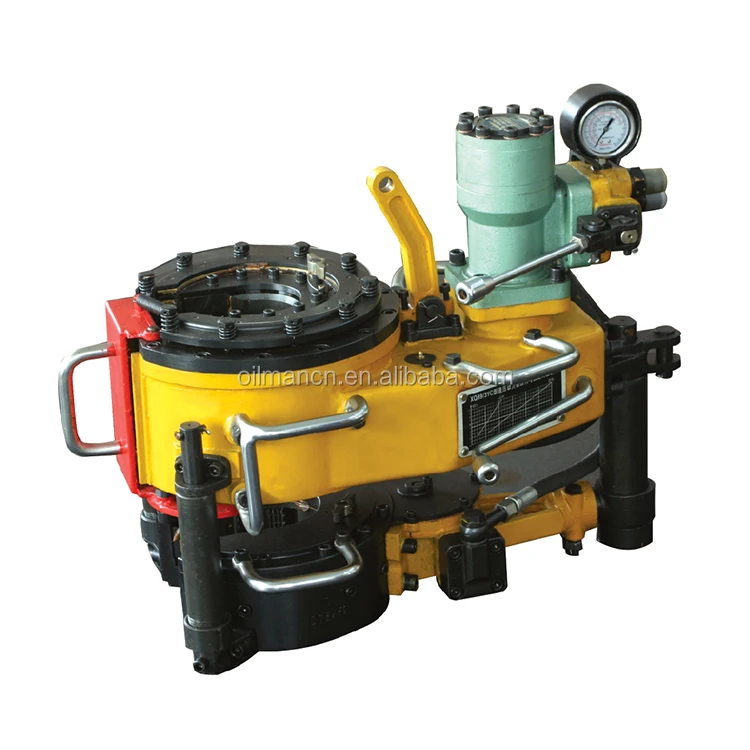
IntroductionKT-9625 9- 5 / 8” TongCongratulations on the purchase of your FARR® KT-9625 9-5/8” tong. This unit will provide you with years of outstandingperformance. Simple maintenance and care will extend its life and ensure years of excellent performance and reliability.The setup, operating, and maintenance instructions in this manual will assist you in giving your equipment thecare it requires. Please carefully read the manual before installing and using your equipment. Replacement parts arereadily available from McCoy Drilling & Completions | FARR in Edmonton, Alberta. Note that many parts are transferablebetween FARR® tongs and backups. Should you need replacement parts, or should you experience any difficultynot covered in this manual, please contact:McCoy Drilling & Completions | FARR14755 121A AvenueEdmonton, AlbertaCanada T5L 2T2Phone: 780.453.3277Fax: 780.455.2432Sales Fax: 780.481.9246Email Engineering: engFarr@mccoyglobal.comEmail Sales: salesFarr@mccoyglobal.comCustomer Care: customerCareFarr@mccoyglobal.comWebsite: http://www.mccoyglobal.com/index.php/drilling-completionsIllustration 1.A.1: KT-9625 Power TongTechnical ManualSection Contents 1.1
SpecificationsKT-9625 9- 5 / 8” TongTorque Table **Pressure High Gear/High Speed Low Gear/Low SpeedPSI / MPa Lbs.-ft. Nm Lbs.-ft. Nm1000 / 6.89 1600 2169 8000 108471300 / 8.96 2200 2983 11000 149141600 / 11.03 2800 3796 13900 188462000 / 13.79 3500 4745 17900 24269MAXIMUM RATED TORQUE: 18000 LBS.-FT. / 24405 NmSpeed TableGear / DisplacementFlow (GPM/LPM) Low/Full Low/Half High/Full High/Half10 / 37.9 2 5 12 2420 / 75.7 5 9 24 4730 / 113.6 7 14 36 7140 / 151.4 9 18 47 95** THESE ARE IDEAL VALUES. ACTUAL ACHIEVED TORQUE IS HIGHLY DEPENDANT UPONTONG EFFICIENCY AND FINAL POSITION OF ROTARY GEAR WHEN FULL TORQUE LOADIS REACHED.Hydraulic Requirements: 40 GPM @ 1000 psi / 151 LPM @ 6.9 MPa20 GPM @ 2000 psi / 75.7 LPM @ 13.8 MPaLength: 40 inches / 101.6 cm.Overall Width: 25-1/2 inches / 64.8 cm.Space Required On Pipe: 8 inches / 20.32 cm.Torque arm length: 32 inches / 81.3 cm.(Line of Pipe Centre Line of Anchor Handle)Weight (Approximate): 1102 lb. / 500 kg.Recommended Spring Hanger: Capacity 600 - 1100 lb (273 - 500 kg)McCoy P/N 85-0106Jaws available (inches): All standard sizes from 2-7/8” to 9-5/8”REPLACEMENT FASTENERS (BOLTS, NUTS, CAP SCREWS, MACHINE SCREWS, ETC.)MUST BE GRADE 8 OR EQUIVALENTTechnical ManualSection Contents 1.3
KT-9625 9- 5 / 8” TongSpecificationsUse an EP synthetic grease that meets or exceeds the following specifications:Thickener Lithium ComplexNLGI consistency grade 2NLGI performance grade GC-LBPenetration - ASTM D 217 (25°C [77°F] 265-295 minimum0.1 mm) worked 60 strokesDropping point, °F[°C] - ASTM D2265 550 [288] minimumHigh temperature life, hours - ASTM D 3527 160 minimumOxidation stability, psi - ASTM D 942 (100 hr/300 hr) 0/3Water washout, percent - ASTM D 1264 1.8 maxRust and corrosion - ASTM D 1743 passOil separation, percent loss - ASTM D 1742 1.1 max(24 hours, 25°C [77°F]Leakage, g lost - ASTM D 4290 1.0 maxFour ball wear test, mm scar - ASTM D 2266 0.40 maxFretting wear, mg - ASTM D 4170 3.4 maxFour ball EP, kgf - ASTM D 2596Weld point 400 minimumLoad wear index 50 minimumTimken OK load test, lbs - ASTM D 2509 50Low temperature torque, N*m - ASTM D 4693 1.3 max(-40°C [-40°F])LT-37 pumpability, g/min 360/7(60°F/0°F [16°C/-18°C])Copper corrosion - ASTM D 4048 1BDisc brake wheel bearing specificationsFord ESA-M1C 198A YesChrysler MS-3701 YesOil viscosity: 40°C [104°F], cSt 151100°C [212°F], cSt 19.2Flash point, °F[°C] - ASTM 92 450[232]Use a premium quality hydraulic fluid that meets or exceeds the following specifications:Typical Density (kg/m 3 ) 878Viscosity - cSt @ 40 °C 68.8- cSt @ 100 °C 8.7Viscosity Index 97Pour Point °F [°C] -22 [-30]Flash Point °F [°C] 432 [222]Colour, ASTM 1.5Neutralization Number 0.40Rust Protection - Distilled Water No Rust- Sea Water No RustHydrolytic Stability - Cu Mass Loss, mg/cm 2 0.04Copper Corrosion Test 1AFilterability: Denison - Wet & Dry PassAfnor - Wet & Dry PassCincinnati Milacron Spec Approved P69Denison HF-0: ApprovedDenison P-46 Piston Pump: PassDenison T6C Vane Pump: PassVickers 35VQ25 Vane Pump Test: Pass104/105C Vane Pump Test: No Data AvailableVane pump test total ring and vane wear, mg.
Setup & OperationKT-9625 9- 5 / 8” TongAdequate setup and proper hydraulic connections are essential in ensuring reliable operation of your tong. For best results and longterm reliability, read and obey the start-up instructions in this section.DO NOT ACCESS ROTATING COMPONENTS UNLESS HYDRAULIC POWER SUPPLY HASBEEN DEACTIVATED OR ISOLATED.A CLEARLY IDENTIFIED REMOTE POWER PACK EMERGENCY STOP MUST BE INSTALLEDIN THE IMMEDIATE VICINITY OF THE TONG OPERATOR.A. SLING / LOAD BEARING DEVICE SAFETYTHE SUPPLIED LOAD-BEARING DEVICE (CHAIN SLING, RIGID SLING, SPREADER BARASSEMBLY, FRAME, OR ANY OTHER DEVICE THAT BEARS THE PARTIAL OR TOTAL WEIGHTOF THE EQUIPMENT DESCRIBED IN THIS MANUAL) HAS BEEN SPECIFIED OR DESIGNED TOSUPPORT THE EQUIPMENT DESCRIBED IN THIS DOCUMENT. FARR WILL NOT GUARANTEETHE ABILITY OF THE LOAD-BEARING DEVICE TO SUPPORT ANY OTHER PART, ASSEMBLYOR COMBINATION OF PARTS AND ASSEMBLIES, OR ANY ADDITIONS TO THE EQUIPMENTDESCRIBED IN THIS MANUAL THAT ADD WEIGHT TO THE EQUIPMENT, UNLESS SUPPLIEDBY FARR CANADA CORP..FARR CANADA CORP. DOES NOT GUARANTEE THE INTEGRITY OF MODIFIED OR DAMAGEDLOAD-BEARING DEVICES, UNLESS THOSE MODIFICATIONS ARE PERFORMED BY FARRCANADA CORP..Farr Canada Corp. recommends following an industry-accepted standard such as OSHA, ASME B30.9-2006, or manufacturer’sguidelines when performing any rigging and overhead lifting. Use by untrained persons is hazardous. Improper use will resultin serious injury or death. Do not exceed rated capacity. Slings will fail if damaged, abused, misused, overused, or improperlymaintained.• Only grade 80 or grade 100 alloy chain should be used for overhead lifting applications.• Working Load Limit (WLL) is the maximum allowable load in pounds which may be applied to the load-bearing device, whenthe device is new or in “as new” condition, and when the load is uniformly and directly applied. The WLL must never beexceeded.• Working Load Limit (WLL) is the maximum working load for a specific minimum sling angle, measured from the horizontalplane. The Working Load Limit is identified on the sling.• The Working Load Limit or Design factor may be affected by wear, misuse, overloading, corrosion, deformation, intentionalalterations, sharp corner cutting action and other use conditions.• Shock loading and extraordinary conditions must be taken into account when selecting alloy chain slings.• See OSHA Regulation for Slings 1910.184, ANSI/ASME B30.9-”SLINGS”, ANSI/ASME B30.10-”HOOKS” and ANSI/AMSEB30.26 “RIGGING HARDWARE” for additional information.THE MINIMUM SLING ANGLE (THE ANGLE OF THE LEG OF THE SLING MEASUREDFROM THE HORIZONTAL) MUST NEVER FALL LOWER THAN THE ANGLE SPECIFIEDFOR THE SLING IN USESling AngleIllustration 2.A.1: Sling AngleTechnical ManualSection Contents 2.1
KT-9625 9- 5 / 8” TongSetup & Operation1. Inspection Of SlingsFarr Canada Corp. strongly recommends the following practices:A complete inspection of new load-bearing devices and attachments shall be performed by a qualified, designated personprior to initial use. Each link and component shall be examined individually, taking care to expose and examine all surfacesincluding the inner link surface. The sling shall be examined for conditions such as those listed in the removal criteria below.In addition, daily inspection of slings, fastenings and attachments shall be performed by a designated person. If damage ordefects are found at either inspection, the damaged or defective component shall be quarantined from service until it canbe properly repaired or replaced.Removal Criteria:A load-bearing device shall be removed from service if conditions such as the following are present:• Missing or illegible sling identification.• Cracks or breaks• Evidence of tampering is seen - sling tag has been modified or obscured, or tamper-proof nuts are missing.• Signs of impact on load-bearing components, including spreader bars, lifting lugs, rigid slings & rigid sling weldments,and legs & leg mounts.• Broken or damaged welds.• Excessive wear, nicks, or gouges. Refer to the chart below to ensure minimum thickness on chain links supplied isnot be below the values listed:Minimum Allowable Chain Link Thickness at Any PointNominal Chain SizeMinimum ThicknessInches MM Inches MM7/32 5.5 0.189 4.809/32 7 0.239 6.075/16 8 0.273 6.933/8 10 0.342 8.691/2 13 0.443 11.265/8 16 0.546 13.873/4 20 0.687 17.457/8 22 0.750 19.051 26 0.887 22.531-1/4 32 1.091 27.71Refer To ASME B30.9• Stretched, bent, twisted, or deformed chain links or components.• Evidence of heat damage.• Excessive pitting or corrosion.• Lack of ability of chain or components to hinge (articulate) freely.• Weld splatter.• For hooks, removal criteria as stated in ASME B30.10• Other conditions, including visible damage, that cause doubt as to the continued use of the sling.Inspect all lugs and fixing points for signs of elongation and/or bending, or for material build-up around the hole. Repair orreplace components that appear distorted. Ensure all hardware is tight and in good condition. Replace missing hardwareif necessary. All hardware must be free of rust and corrosion.Additional inspections shall be performed during sling use where service conditions warrant. Periodic inspection intervalsshall not exceed one year. The frequency of periodic inspections should be based on:• Frequency of use of the load-bearing device.• Severity of service conditions• Nature of lifts being made• Experience gained on the service life of load-bearing devices used in similar circumstances.Guidelines for the interval are:• Normal Service: Yearly• Severe Service: Monthly to quarterly• Special Service: As recommended by a qualified person2.2Section ContentsTechnical Manual
Setup & OperationKT-9625 9- 5 / 8” TongUnits designed and manufactured in accordance with EN 12079 and DNV 2.7-1 should be tested and examined in accordancewith the following schedule of examination and test. The user of the load-bearing device shall place a permanentplacard or plate upon which the type and date of the last test shall be recorded. To avoid confusion, the plate shall not carrythe date of the next test or examination, only the most recent.Test / ExaminationTime / Interval Lifting Tests 1 Lifting PointsNon-DestructiveExamination (NDE) ofInitial Certification ByFarr / SuperiorInterval Not Exceeding12 MonthsInterval Not Exceeding60 MonthsThoroughVisualExaminationSuffix To Be MarkedOn Plate AttachedTo UnitYES YES YES TAt the discretion ofinspection bodyAt the discretion ofinspection bodyAt the discretion ofinspection bodyYES T or VN 3YES YES T or VNFollowing SubstantialYES YES YES TRepair or Alteration 41. Lifting test as per S 7.3 BS EN 12079 or DNV 2.7-1 May 19952. T = Proof Test, non-destructive examination; VN = non destructive examination and visual examination;V = visual examination.3. Dependant upon whether non-destructive examination has been carried out.4. For the purposes of this standard, a substantial repair or modification is defined as any repair and/ormodification that has been carried out which may, in the opinion of the inspection body, affect the loadbearingelements of the container or lifting device, or elements that contribute directly to its structuralintegrity.IF MECHANICAL DAMAGE IS SEEN OR SUSPECTED ON A LOAD-BEARING DEVICE, ORIF THE LOAD-BEARING DEVICE HAS BEEN OVERLOADED, IT MUST BE REMOVED FROMSERVICE AND QUARANTINED UNTIL RECERTIFIEDWritten records of the most recent periodic inspection shall be maintained, and shall include the condition of the sling.2. Proper Use Of Load-Bearing DevicesWhenever any load-bearing device is used, the following practices shall be observed.• Load-bearing devices that are damaged or defective shall not be used.• Slings shall not be shortened with knots or bolts or other makeshift devices.• Sling legs shall not be kinked.• Load-bearing devices shall not be loaded in excess of their rated capacities.• Slings shall be securely attached to their load.• Load-bearing devices shall be protected from snagging, and shall not be further obstructed by any object.• Suspended loads shall be kept clear of all obstruction.• All employees shall be kept clear of loads about to be lifted and of suspended loads.• Hands or fingers shall not be placed between the sling and its load while the sling is being tightened around the load.• Shock loading is prohibited.• Do not stand directly under a load during lifting.3. Storage Of Load-Bearing DevicesProper storage of out-of-service load bearing devices is important to ensure full integrity of the device once it is returnedto service. Farr recommends observing the following practices:• Wipe off all excess grease. Use a solvent-based cleaner on rags to wipe all external surfaces to remove residualgrease or hydraulic fluid. Once the outside surfaces have been de-greased, wipe all external surfaces with clean waterto remove residual solvent.• Farr recommends that an anti-corrosive agent such as Tectyl ® 506 be applied to all external surfaces. Refer to manufacturerdata sheets for proper application and safety information. Allow the anti-corrosive coating ample time to dry- refer to manufacturer data sheets for drying times at room temperature.• Store in a clean, dry location. When returning to service, note that a full inspection of the device must be performed.Technical ManualSection Contents 2.3
KT-9625 9- 5 / 8” TongSetup & OperationB. MAJOR COMPONENT IDENTIFICATION67891234510Illustration 2.B.1: Major Component Identification 012.4ItemDescription1 Tong Leveling Adjustment2 Rigid Sling3 Backing Pin Assembly4 Cage Plate Assembly5 Tong Door Cylinder6 Master Link7 Rigid Sling8 Hydraulic Valve Assembly9 Hydraulic Tubing Mount10 Tong DoorSection Contents Technical Manual
Setup & OperationKT-9625 9- 5 / 8” Tong111213Illustration 2.B.2: Major Component Identification 02Item11 Hydraulic Motor12 Torque Gauge Mount13 Motor MountDescriptionTechnical ManualSection Contents 2.5
KT-9625 9- 5 / 8” TongSetup & Operation1415161718Illustration 2.B.3: Major Component Identification 03ItemDescription14 Safety Door Plunger Switch15 Brake Band (top brake band shown - bottom brake band is identical)16 Brake Band Adjustment (top adjustment shown - bottom adjustment is identical)17 Manual Shift Assembly18 Shifter / Gear Train Inspection Panel2.6Section ContentsTechnical Manual
Setup & OperationKT-9625 9- 5 / 8” TongC. HYDRAULIC SCHEMATIC / COMPONENT IDENTIFICATIONOPTIONAL12141011OPTIONALTO LIFT9813PT1 2 3 4 67OPTIONALIllustration 2.C.1: Hydraulic SchematicItem Description Part Number Page1 Inlet Valve c/w safety door cartridge 101-3927A 2.82 Relief Valve, DVA35-MRV-1 10-0010R 2.83 Pilot-To-Open Valve, Sun LKHC-XDN 08-1625 2.94 Motor Section, DVA35-MA8, 4WAY SAE PORTS 10-9014 2.86 Lift Cylinder Section, DVA35-SA8, 1” ORB PORT (Optional) 10-9015 2.87 Outlet Section, DVA35-TR99, SAE PORT 10-0086 2.88 Flow Control Valve, Parker N800S 08-9062 Not Shown9 Safety Door Switch 08-0337 2.810 Motor Shift Valve, Bailey ED Series 220-906 10-9035 2.811 Check Valve (Optional) 08-9022 Not Shown12 Rineer GA15-13/6.5 Hydraulic Motor 87-0008 2.813 DVA35 Transition Plate 101-3935 2.814 3000 psig Pressure Gauge 02-0246 Not ShownTechnical ManualSection Contents 2.7
KT-9625 9- 5 / 8” TongSetup & Operation107613412Illustration 2.C.2: Hydraulic Component Identification 019122.8Illustration 2.C.3: Hydraulic Component Identification 02Section ContentsTechnical Manual
Setup & OperationKT-9625 9- 5 / 8” Tong3Illustration 2.C.4: Hydraulic Component Identification 03D. HYDRAULIC CONNECTIONSA pair of hydraulic lines - a 1” supply line and a 1-1/4” return line - connect the tong to the power unit (see illustration below).The valve block provides hydraulic power to ancillary devices (hydraulic motors, hydraulic cylinders, etc.).Perform any hydraulic connection when the power unit is not running, or when the hydraulic pump is disengaged. The possibilityof error in inter-changing the high pressure supply hose and the low pressure return hose has been eliminated, because thesupply side coupling is smaller than the return side.1” HydraulicSupply1-1/4” HydraulicReturnIllustration 2.D.1: Hydraulic Connections 01Technical ManualSection Contents 2.9
KT-9625 9- 5 / 8” TongSetup & OperationThese hose couplings are self-sealing, and care should be taken to ensure complete engagement to prevent partial closure ofthe check valve in the coupling. Ensure that the nut (female) side is completely made up onto the male connector - there is aline on the male fitting that indicates complete make-up. Snug the female fitting right up to the line.Make up female fitting toMarked point on male fittingE. TONG / BACKUP JAW AVAILABILITY & INSTALLATIONIllustration 2.D.2: Hydraulic Connections 02The following table lists all jaw die kits that are available as standard sizes for this model of tong. If your desired size is not listed,Farr can engineer custom jaw sizes - contact sales for further information.DescriptionPart Number2-7/8” Jaw Die Kit 1 AK21-JDK-28753-1/2” Jaw Die Kit 2 AK21-JDK-35004” Jaw Die Kit AK21-JDK-40004-1/2” Jaw Die Kit AK21-JDK-45005” Jaw Die Kit AK21-JDK-50005-1/2” Jaw Die Kit AK21-JDK-55005-3/4” Jaw Die Kit AK21-JDK-57506-5/8” Jaw Die Kit AK21-JDK-66257” Jaw Die Kit AK21-JDK-70007-5/8” Jaw Die Kit AK21-JDK-76258-5/8” Jaw Die Kit AK21-JDK-86259-5/8” Jaw Die Kit AK21-JDK-96251Uses jaw die 12-00072Uses jaw die 12-0011All remaining jaw die kits use flat die PN 12-1004If necessary the entire jaw may be removed. Support the jaw from the bottom and remove the jaw pivot bolt. The jaw may thenbe slid out of and away from the cage plate. Reverse this procedure to replace the jaw assemblies (see Illustration 2.E.1)2.10Section ContentsTechnical Manual
Setup & OperationKT-9625 9- 5 / 8” TongIllustration 2.E.1: Jaw ReplacementOnce the jaw has been removed the jaw dies may be replaced by removing the keeper screw above the die, and tap the diefrom jaw using a hammer. Replace the die, tapping it into place if necessary, and replace the keeper screws.F. TONG RIG-UP & LEVELING1. Suspension & RestraintSuspend the tong from a location as near to the centre of the drill rotary as possible, and from a location high enough onthe mast to ensure easy handling. The lower the point from which the tong is suspended, the more effort will be requiredto move the tong to and from the connection point.The suspension line may be extended over a pulley and balanced by a counterweight equal to the weight of the tong, orsimply tied off in the derrick to form a dead line. When using a dead line arrangement it is necessary to use a FARR springhanger assembly (see specification page for recommended spring hanger). This spring hanger compensates for the downwardmovement of the casing as the thread is made-up, and imparts additional force to the suspension cable:• a “single spring” hanger typically applies 420 lbs. (191 kg.) to the suspension line for every inch of thread made up• a “double spring” hanger typically applies 840 lbs. (382 kg.) to the suspension line for every inch of thread made upIf you do not know which specific spring hanger is in use, check the specification page in this manual for information on therecommended spring hanger for this application. McCoy Drilling & Completions will not guarantee or specify spring hangersother than what has been supplied by McCoy.Many applications use a lift cylinder for adjusting the height of the tong. Ensure the weight of the lift cylinder is known if ithas not been included in the total weight of the tong.All forces upon the suspension line must be considered when calculating necessary strength of the suspension line. Theweight of the tong, the weight of the lift cylinder, the weight of the spring hanger, and the force imparted on the suspensionline by the spring hanger must all be added together in order to arrive at the total force supported by the suspension line.Select your suspension line based upon the total force and the margins of safety dictated by the policies of your companyand by established engineering practices. Ultimately, calculating the force on the suspension line and selection of the suspensionline is the complete responsibility of the customer.McCoy Drilling & Completions recommends using dual backup (snub) lines of sufficient strength to withstand the forceimparted by the maximum rated torque of the tong in use. Calculate the force on the snub lines by dividing the maximumtorque of the tong by the tong’s torque arm (expressed in feet). For example, an 18,000 lbs.-ft. tong with a 31 inch (2.583ft.) torque arm will generate 6968.6 lbs. of force against the snub line. Select your snub lines based upon the total forceand the margins of safety dictated by the policies of your company and by established engineering practices. Ultimately,calculating the force on the snub line and selection of the snub line is the complete responsibility of the customer.Technical ManualSection Contents 2.11
KT-9625 9- 5 / 8” TongSetup & OperationSuspension & Restraint (Cont’d)Snub lines must be securely connected to the rear of the tong, and tied off to a suitable anchor. One snub line must besecured to the load cell, which is then secured to the rear of the tong. The side of the tong the load cell connects to isdependant upon whether make-up or break-out activities are underway. To ensure accurate torque measurement, thetorque measurement line must be connected perpendicular to the lengthwise axis of the tong, and perpendicular to thehang line (see illustrations 2.F.1 and 2.F.2). Connect the second snub line on the opposite side of the load cell, perpendicularto the lengthwise axis of the tong and perpendicular to the vertical.FARR CANADA CORP. ACCEPTS NO RESPONSIBILITY FOR DESIGNING AND SELECTINGAN ADEQUATE SUSPENSION AND RESTRAINT SYSTEM FOR YOUR DRILLING EQUIPMENTALL SELECTED FASTENERS, SHACKLES, CLAMPS, ETC. USED FOR CONSTRUCTING THESUSPENSION AND SNUB LINES MUST BE RATED FOR THE CALCULATED FORCES.90 oIllustration 2.F.2: Tong Suspension Relative To Axial Centre (LW 9/58” Shown)90 oIllustration 2.F.1: Tong Suspension Relative To Vertical Centre (LW 9/58” Shown)2.12Section ContentsTechnical Manual
Setup & OperationKT-9625 9- 5 / 8” Tong2. Tong LevelingThe tong must be leveled side-to-side and front-to-rear before placing into service. The following guidelines will assist youwhen leveling your tong.i. Place a level axially (side to side) across the tong, ensuring that it is parallel with the surface of the tong. Use a thinwrench on the flat of the adjusting helix to rotate the helix, forcing the lift link to move towards the outer supports ofthe sling. The 3/4” nylock nut on the pin may have to be slightly loosened to allow the helix to rotate. Adjust the helixuntil the level shows that the tong is level side-to-side.Rotate helixusing flat3/4” Nylock nut mayhave to be loosenedii.Illustration 2.F.3: Tong Leveling (Side-To-Side)Place a level lengthwise (front to back) along the tong, ensuring that it is parallel with the surface of the tong. Loosenthe 1/2” jam nuts on the adjusting bolts on rigid sling brackets. Completely loosen the adjusting bolts. Turn eachadjusting bolt equally until tong hangs level front-to-back. Lock adjusting bolts in place with the jam nuts.Loosen 1/2” hex jam nut beforerotating adjustment boltIllustration 2.F.4: Tong Leveling (Front-To-Rear)Technical ManualSection Contents 2.13
KT-9625 9- 5 / 8” TongSetup & OperationG. TONG OPERATION1. Initial Start-up and Break-in ProcedureYOUR EQUIPMENT HAS BEEN THOROUGHLY TESTED AND INSPECTED AT THEFACTORY. HOWEVER, WE ADVISE INSPECTION AND TESTING OF YOUR NEW TONGAFTER TAKING POSSESSION IN ORDER TO ELIMINATE THE POSSIBILITY OF SHIPPINGDAMAGE.McCoy Completions & Drilling recommends that the following pre-operating tests be performed after receipt from the factoryor after extended storage, prior to releasing the tong to operations:• Perform a complete inspection of all fasteners to ensure none have loosened during transport.• Connect the tong to the power unit, and apply full hydraulic pressure. Inspect and correct any leaks.• Operate the tong at full speed and in high gear for a duration of one-half hour. Hot bearing caps may indicate impendingbearing failure.• Switch to low gear and operate for an additional one-half hour at full speed.• Run the backup through several clamp/un-clamp sequences to ensure functionality.• Inspect all components and hydraulic fittings for possible defects following completion of the tests. All FARR Tongshave been thoroughly tested at the factory prior to shipping, but shipping damage must be identified before running thetong in an operational environment.• Carefully inspect the safety door components, and test to ensure that the safety device on each door is operating correctlybefore releasing the tong to the operating environment.TONG DOOR MUST BE CLOSED AND SECURELY LATCHED BEFORE THE POWER UNIT ISSTARTED IN ORDER TO ASSURE THE SAFETY OF OPERATING PERSONNELEnsure adequate lube oil and hydraulic oil levels before starting engine. Use start up procedures as recommended by thepower unit engine operator’s manual. Open the Bypass Valve on the hydraulic system, and inspect all pressure and returnline hose connections to ensure correct and secure installation.IMPROPERLY SECURED HYDRAULIC CONNECTIONS WILL INTERRUPT HYDRAULIC FLUID FLOW, ANDCOULD RESULT IN THE FOLLOWING FAILURES:• A restriction in the pressure supply hose will result in high pressure within the power unit hydraulic system, whichwill activate the hydraulic governor and increase the engine speed to as high as maximum RPM.• A restriction in the return line will result in high pressure within the power unit and the tong hydraulic system, causingengine speeds as high as maximum RPM, and possible failure of the motor seal.Following inspection of the hoses, start the engine and allow it to idle until warm. Allow hydraulic fluid to circulate forapproximately 10 minutes, then slowly close the Bypass Valve to allow hydraulic fluid to circulate through the hoses andto the tong (circulating pressure should not exceed 200 psi). Place the tong gear shifter in low gear and rotate the tongslowly forward and then reverse with the throttle valve control lever. Once this has been done and the proper size jawshave been installed, the tong is then ready to run pipe.2. Valve Operation4-way proportional valves control operation of hydraulic devices on the tong assembly such as hydraulic motors and cylinders.When any one valve is “centered” or in the detent position, there is no hydraulic output from the valve. When thevalve is pushed forward there is an effect, and when the valve is pulled back, there is an opposite effect. These valvesfeature proportional control, which means that further extension of the valve handle (thereby further opening the valveorifice) results in proportionally higher hydraulic output to the controlled device.The following illustration demonstrates the type and effect of the hydraulic valves with which this tong is may be equipped.2.14Section ContentsTechnical Manual
Setup & OperationKT-9625 9- 5 / 8” TongTONG MOTORThis is a proportional valve. Pushing the valve handle forward will cause the tong motor to rotate in a clockwise direction(as seen from the top of the tong). This is the desired direction of rotation for making up a joint. Pulling the valve handle inthe opposite direction results in counter-clockwise rotation, which is the desired direction of rotation for breaking out a joint.Illustration 2.G.1: Tong Rotation Control ValveLIFT CYLINDERThis is a direct-acting valve. Pushing the valve handle forward will cause the lift cylinder to lift the tong vertically. Pullingthe valve handle in the opposite direction will cause the lift cylinder to lower the tong.Illustration 2.G.2: Tong Lift Cylinder Control ValveTechnical ManualSection Contents 2.15
KT-9625 9- 5 / 8” TongSetup & OperationMOTOR SPEEDThis valve sets the speed of the two-speed motor. Pulling the motor speed control all the way out sets the motor speed toLOW. Maximum torque is only available when the motor speed is set to LOW. Pushing the valve handle towards the centreof the tong sets the motor speed to HIGH, which is useful for rapidly un-threading broken connections.Low SpeedHigh SpeedIllustration 2.G.3: Tong Motor Speed Control Valve3. Shifting GearsThe shifting shaft has three “detent” positions identifying the low speed/high torque position, the “neutral” or free-spinningposition, and the high speed/low torque position. The detent strength may be adjusted by releasing the locknut on thedetent tube and increasing or relaxing pressure on the detent spring. Ensure the locknut is tightened once the desireddetent pressure has been set.To shift to the high-speed gear, move the shifting handle upward from neutral position. To shift to the low-speed gear, movethe shifting handle down through the neutral detent to its lowest position. Note that the high clutch gear or the low clutchgear may not be exactly aligned when shifting, so the operator may need to “bump” the motor control handle slightly toturn the main clutch gear shaft and shifting collar into alignment. This is most effective when applying a small amount ofpressure on the gear shift lever in the direction you want to shift the tong, ensuring the shifting collar will “catch” when themain clutch gear aligns with either the high or low clutch gear (see Illustration 2.G.4 next page).SHIFTING TONG WHILE ROTATING THE MOTOR AND CAGE PLATE MAY RESULT INCATASTROPHIC GEAR TRAIN FAILURE2.16Section ContentsTechnical Manual
Setup & OperationKT-9625 9- 5 / 8” TongLIFT HANDLE TOSHIFT TO HIGH GEARPUSH HANDLE DOWNTO SHIFT TO LOW GEARIllustration 2.G.4: Tong Manual Shift Control4. General Commentsa) Position rotary gear in contact with both idler gears when breaking out joints or collars where high torques arerequired.b) When making-up integral (shouldered) joints, it is essential to make up the last turn of the threads in low gear. Thisreduces the tendency of an instant stop or a sudden increase in torque, which induces extremely high stresses on thegear train.c) DO NOT employ the “snap break” method of breaking-out joints when pulling a string. By definition, the “snap break”method is a procedure used by some operators to break out connections, accomplished by leaving slack in the “jawpipe”engagement, and then quickly pulling the throttle valve control lever allowing the tong to snap into its loaded orhigh torque condition. Although this method is very effective in breaking out joints, the extremely high stress placedon the gear train frequently causes gear breakage.Technical ManualSection Contents 2.17
KT-9625 9- 5 / 8” TongSetup & OperationH. MAKING AND BREAKING CONNECTIONSTHESE OPERATING PROCEDURES ASSUME THE USER HAS PROPERLY SET UP AND PRE-PARED THE EQUIPMENT FOR OPERATION AS PER SECTIONS 2D, 2E, AND 2F OF THISMANUAL.Set up and prepare your equipment for operation as per Section 2 of this manual Refer to the following sections:• 2.D - Hydraulic Connections• 2.E - Tong Jaw Installation• 2.F.1 - Tong Rig-up and Leveling (Suspension)• 2.F.2 - Tong Rig-up and Leveling (Leveling)Your tong and backup assembly should be properly suspended, connected to a hydraulic power source, and ready to make orbreak connections at this point.1. Making A Connectiona) Ensure hydraulic power supply to the tong is energized. The master link on the rigid sling must be used to suspendthe tong. Do not suspend the tong directly from the rigid sling.Illustration 2.H.1: Master Lifting LinkTHE MASTER LINK MUST BE USED TO SUSPEND THE TONG ASSEMBLYb) Ensure the backing pin is in the “makeup” position. From the front of the tong, the backing pin correctly configured formakeup will be in the 10 o’clock position (see Illustration 2.H.2 next page). If it is not, simply lift up and place in thecorrect position (see Illustration 2 next page). The cage plate opening must be aligned with the door opening whensetting the backing pin position.2.18Section ContentsTechnical Manual
Setup & OperationKT-9625 9- 5 / 8” TongMaking A Connection (Continued)Illustration 2.H.2: Setting Backing Pin To “Make-up” Positionc) Ensure the load cell and snub line(s) are properly configured for making up connections. The “snub line” is a lengthof wire rope that connects the rear of the tong body to a sturdy anchor on the drill floor (see Section 2.F.1). The snubline prevents the tong body from spinning in the opposite direction of the cage plate when torque begins to build in thejoint. The snub line must be rated for the applied torque plus whatever safety margins stated by your own operatingpolicies. The snub line connection point on the drill floor must be sturdy enough to absorb all applied forces whenmaking up the joints. When making up joints the snub line is attached to the driller’s side of the tong, which is the leftside of the tong as seen from the rear. For accurate torque measurement the snub line must be perpendicular to thevertical, and perpendicular to the centre-line of the tong.d) Actuate the lift cylinder control valve to lift the assembly from the drill floor. Pushing the valve toward the center of thetong will retract the lift cylinder to lift the assembly (see Illustration 2.H.3 below). Note that rig personnel are requiredto stabilize the tong and backup as it is being lifted so it does not swing and collide with other rig equipment.RIG PERSONNEL MUST STABILIZE THE TONG AS IT IS LIFTED FROM THE DRILL FLOORIllustration 2.H.3: Lift Cylinder Control - RaiseTechnical ManualSection Contents 2.19
KT-9625 9- 5 / 8” TongSetup & OperationMaking A Connection (Continued)e) Grasp the tong door handle and pull the door to open (See Illustration 2.H.4 next page). Since your equipment isequipped with a safety door, opening the door will inhibit rotation of the cage plate.Door HandleLatch PostIllustration 2.H.4: Opening Tong Doorf) Manually engage the threads of the tubing connection being made up. Ensure threads are not cross-threaded.g) Move the tong on to the tubing joint. Use the lift cylinder to ensure the tong jaws are at the correct location above theconnection joint.h) Firmly close the tong door against the latch post.i) Ensure tubing is roughly centered within the tong jaws - rig personnel are required to stabilize the tong above theconnection until the jaws have made full contact with the pipe or casing.j) Begin rotation with the tong in high gear and the tong motor set to high speed (high speed/low torque). See Section2.G.2 to set the tong motor to high speed, and Section 2.G.3 to properly set the tong to high gear. Do not shift gearswhile the tong is rotating.SHIFTING TONG WHILE ROTATING THE MOTOR AND CAGE PLATE MAY RESULT INCATASTROPHIC GEAR TRAIN FAILUREk) Push the motor control valve toward the tong to rotate the cage plate in the make-up direction.2.20Section ContentsIllustration 2.H.5: Motor Control - Make-upTechnical Manual
Setup & OperationKT-9625 9- 5 / 8” TongMaking A Connection (Continued)l) When the tong jaws cam on to the tubing push the rotation control handle all the way in to thread the connectiontogether at high speed. As the joint becomes fully made up the increasing torque demand will stall the motor, anddisplayed torque will increase.m) Stop rotation, and set motor to low speed and shift to low gear (low speed/high torque - See Section 2.G.2 for instructionsfor setting motor to low speed, and Section 2.G.3 for shifting to low gear). This will enable the tong to produceadequate torque for making up the joint to specification.n) Push the rotation control handle all the way in to complete the connection at low speed/high torque. Observe thetorque gauge - when the specified make-up torque is reached stop rotation. Reverse the rotation control valve torelease the tong jaws from the tubing (see Illustration 2.H.6).Illustration 2.H.6: Motor Control - Releasing JawsMaking A Connection (Continued)o) When tong jaws are free, align the opening in the rotary gear with the mouth of the tong, and open the tong door tofree the tong from the drill string. Note that rig personnel may be required to stabilize the tong as it completely releasesfrom the drill string. Guide the tong away from the string and use the lift cylinder control to lower it to the drill floor ifdesired.Illustration 2.H.7: Lift Cylinder Control - LowerTechnical ManualSection Contents 2.21
KT-9625 9- 5 / 8” TongSetup & OperationMaking A Connection (Continued)p) Repeat steps “f” through “o” until the desired number of connections are made up.2. Breaking A ConnectionYOUR TONG SHOULD BE PROPERLY SUSPENDED, CONNECTED TO A HYDRAULIC POWERSOURCE, AND READY TO BREAK CONNECTIONS.a) Ensure hydraulic power supply to the tong and backup is energized. The master link on the rigid sling must be usedto suspend the tong. Do not suspend the tong directly from the rigid sling. See Illustration 2.H.1.b) Set the backing pin for “breakout” operation. Lift up on the backing pin and rotate it to the “breakout” position, which is2 o’clock as seen from the front of the tong. The opening in the rotary gear must be aligned with the tong door openingin order to properly set the backing pin (see Illustration 2.H.8).Illustration 2.H.8: Setting Backing Pin To “Break-Out” Positionc) Ensure the load cell and snub line is configured for break-out operation. The snub line and load cell must be transferredto the off-driller’s side (the right hand side as seen from the rear of the tong) to perform break-out operations.d) Open the tong door (see Illustration 2.H.4).e) Actuate the lift cylinder control valve to lift the assembly from the drill floor if necessary. Pushing the valve toward thecenter of the tong will retract the lift cylinder to lift the assembly (see illustration 2.H.3). Note that rig personnel arerequired to stabilize the tong and backup as it is being lifted so it does not swing and collide with other rig equipment.RIG PERSONNEL MUST STABILIZE THE TONG AS IT IS LIFTED FROM THE DRILL FLOORf) Move the tong on to the tubing joint. Use the lift cylinder to ensure the tong jaws are at the correct location above theconnection joint.g) Firmly close the tong door against the latch post.h) Ensure tubing is roughly centered within the tong jaws - rig personnel are required to stabilize the tong above theconnection until the jaws have made full contact with the pipe or casing.i) Breakout torque is only available when tong motor speed is set to low speed and tong is in low gear. See Section2.G.2 to set tong to low speed and Section 2.G.3 to shift to low gear. Do not shift gears while the tong is rotating.2.22Section ContentsTechnical Manual
Setup & OperationKT-9625 9- 5 / 8” TongBreaking A Connection (Continued)SHIFTING TONG WHILE ROTATING THE MOTOR AND CAGE PLATE MAY RESULT INCATASTROPHIC GEAR TRAIN FAILUREj) Pull the motor control valve toward the operator to rotate the cage plate in the break-out direction.Illustration 2.H.9: Rotation Control - Break-Outl) When the tong jaws cam on to the tubing pull the rotation control handle all the way out to break the connection.m) When the connection breaks stop rotation, set tong motor to high speed and shift to high gear (see Section 2.G.2 toset motor speed and 2.G.3 to shift to high gear). This will enable the tong to completely un-thread the connection athigh speed.n) Pull the rotation control handle all the way out to completely un-thread the connection. Reverse the rotation controlhandle (push toward tong) to release the tong jaws from the tubing (see Illustration 2.H.10 next page).Illustration 2.H.10: Releasing Tong Jaws Following Break-out & Un-threadingTechnical ManualSection Contents 2.23
KT-9625 9- 5 / 8” TongSetup & OperationBreaking A Connection (Continued)o) When the tong jaws disengage align the opening in the rotary gear with the mouth of the tong, and open the tong doorto free the tong from the drill string. Unlatch and open the tong door to free the assembly from the tubing. Note that rigpersonnel may be required to stabilize the equipment as it completely releases from the tubing. Guide the assemblyaway from the string and use the lift cylinder control to lower it to the drill floor if desired.Illustration 2.H.11: Lowering Tong Using Lift Cylinder Controlp) Use your rig’s standard pipe handling procedures to remove and rack the freed tubing stand.q) Repeat steps “e” through “p” as many times as necessary to break out and un-thread the desired number of connections.H. EXTREME COLD WEATHER OPERATION PROCEDURES1) Consult the power unit engine operator’s manual for all cold weather operating procedures and precautions.2) Select gear and bearing lubricants that are compatible with expected climatic conditions.3) Select hydraulic fluid that is compatible with expected climatic conditions.4) Allow hydraulic fluid to circulate for approximately 20 minutes after starting the power unit, prior to activating thebypass valve to allow fluid to circulate to tong. If the power unit is equipped with an oil temperature gauge, ensurethat the fluid has reached operating temperature as specified by hydraulic fluid data sheet.5) Allow for adequate drying of moisture (prior to lubricating) when cleaning tong parts in cold weather.2.24Section ContentsTechnical Manual
MaintenanceKT-9625 9- 5 / 8” TongMcCoy Completions & Drilling recognizes that minor on-site repairs and modifications are required to maintain peak operating conditionof your equipment, or to match your equipment with the operating environment. Examples of minor repairs are• replacement of damaged hydraulic hoses and fittings.• replacement of malfunctioning pressure gauges and valves.• replacement of door cylinders• replacement of fastenersAny replaced component must be an identical component supplied by McCoy Completions & Drilling. Replaced fasteners must beGrade 8 or equivalent, or whatever fastener is specified by McCoy.A. GENERAL MAINTENANCE SAFETY PRACTICESThe practices identified here are intended as a guideline. All personnel are responsible for performing their tasks in a mannerthat ensures worker, equipment, and environmental safety, and may require taking additional steps that are not identified inthis section.Equipment maintenance shall be performed only by designated qualified maintenance personnel. Wear approved eye wearand foot wear, and follow all of your company’s safety guidelines Do not begin a maintenance task without the proper tools ormaterials on hand, or the proper drawings and documentation necessary.Schedule planned maintenance with operators to avoid conflicts, unnecessary downtime, and the danger of accidental equipmentactivation. Notify operations when maintenance procedures are complete and equipment functionality is restored.Isolate the location of the maintenance under way to prevent unaware personnel from inadvertently exposing themselves to ahazard. Use tape, rope, or signs to clearly indicate “off-limits” area.Replacement of large, heavy individual parts and/or heavy structural components must be performed using an approved liftingdevice of sufficient lifting capacity. Use care when attaching the lifting device, and safeguard area to avoid endangering personnelor equipment.All spare parts must meet or exceed OEM specifications in order to maintain equipment integrity, especially protective equipmentMcCoy recommends that disconnection of hydraulic connectors be performed with the power unit off and the hydraulic circuitdepressurized.Your equipment uses materials that may be harmful to the environment if improperly disposed of (hydraulic fluid, grease, etc.).Dispose of all materials according to your company’s proscribed environmental protection regulations.B. CLEANINGClean tong thoroughly cleaned with a good petroleum-based cleaning agent after each job, prior to storage. Farr recommendsthat the motor and valve assembly be periodically removed, along with the top tong plate, so that guides, rollers and gears canbe properly cleaned. Ensure that cleaning solvents and chemicals are captured to prevent environmental contamination, anddispose of all materials according to your company’s proscribed environmental protection regulations.C. PREVENTIVE MAINTENANCERegular maintenance programs are necessary, and must be established to assure safe, dependable operation of your HydraulicTubular Connection System and to avoid costly breakdown maintenance. The following maintenance procedures providesinformation required to properly maintain your equipment. Your equipment may require more, or less maintenance dependingupon the frequency of use and the field conditions under which your equipment operates. These maintenance procedures aredesigned for equipment operating at 10°C to 35°C ambient temperature for 10 hours per day. McCoy recommends that theinspection and maintenance procedures in this section be performed as recommended in the maintenance checklists (seeAppendices), or in conjunction with your maintenance foreman’s experience and best estimate of when your equipment is duefor this maintenance.Purchased components included with your hydraulic tubular connection equipment (for example: motors, valves, etc.) mayspecify maintenance tasks and intervals over and above what McCoy recommends as part of their recommended procedures.Users of this equipment may choose to perform or ignore these additional tasks at their discretion.Premature fouling of particulate filters within your prime mover or ancillary hydraulic power unit requires immediate hydraulicfluid laboratory analysis to prevent premature wear of hydraulic system due to high levels of wear metals in the fluid.McCoy Completions & Drilling recommends tracking all maintenance activity including the lubrication schedule. This may be asimple as keeping a paper log, or using a software-based maintenance tracking utility. A maintenance log is a valuable tool thatcan be used for easily retrieving maintenance history or identifying trends that require correction.Technical ManualSection Contents 3.1
KT-9625 9- 5 / 8” TongMaintenanceD. LUBRICATIONUse a quality multipurpose bearing lubricant that will remain within its viscosity range at expected operating temperatures. Inaddition, Farr recommends the following lubrication procedure at


 8613371530291