
power tong companies in alberta free sample

Universe Machine Corporation"s driving mission is to manufacture, modify or repair steel products for the oilfield, petrochemical and forestry industries. The company has been providing these services since 1965 and owes its success to a highly skilled workforce and a commitm…
At Ed"s Valve Servicing (Red Deer) Ltd., we"re known for quality workmanship. After 25 years of service in the Red Deer area, we understand that there"s no substitute for hard work and accuracy.
Pathmaker is an expanding Tubular Running Service company developed Industry professionals with remarkable TRS experience and expertise. We are family owned and operated and have been proudly serving Alberta and British Columbia Industry for over 40 years.
Dash Energy Services Ltd. provides complete tubular services, integral and conventional power tongs, CRT"s, computer torque monitoring, thread washing, 12 GPS equipped units and more, all provided with professional, competent service.;Dash Energy Services Ltd. has been in busine…
Ace Power Tongs & Energy Services serves Western Canada with computer torque monitoring, thread washing, CRT"s, integral and power tongs, GPS equipped units and more. Click our name to learn more about us.;Your choice for a complete tong, casing and tubing program is Ace Power …
When you need to put down or remove pipes for an oil drilling rig, trust Bitz Power Tongs Ltd. to handle the work. We have a variety of power tong trucks in Edson, Alberta, to meet the needs of your project. Our Canadian-owned and locally operated power tong and laydown unit com…
TriMark Tubular Ltd. delivers high-quality oil country tubular goods (OCTG) used for drilling and completions, plus gathering and transmission lines. We hold one of the largest inventories of OCTG and linepipe in Western Canada. TriMark provides complementary engineering experti…
Hill"s Power Tongs has provided Alberta with "First Class Tools All The Way - Any Time Night or Day", since 1975. Offering: Integral tongs and Computer torque monitoring We are certified: ISnetworld, ComplyWorks and COR. Offering 24 hour service. Please call or email.
Pro Torque Connection Technologies Ltd. offers a full line of casing running services: conventional and integral power tong equipment, Volant casing running tools, computer torque monitoring, casing crews, and thread supervision and inspection. We also offer top drive and iron r…
An oilfield service company, Hybrid Energy Services relies on the latest technology to create accountability and reduce liability for its clients. They offer a wide range of services, including the following: computer-analyzed torque monitoring, wireless torque sub, electroni…
Drifters Casing Service is a local leader for drilling and completions work in Grande Prairie, Whitecourt, and other areas in Alberta. You can count on us to provide services 24 hours per day as required.

In your work you rely on having suppliers who use the best equipment to complete your jobs. Among the most important pieces of equipment required for oil drilling and completions are power tongs. Drifters Casing Service is a local provider of power tongs services in Grande Prairie and Whitecourt areas with a reputation for expertise and reliability.
Eckel.Eckel is the one of the world’s leading power tong manufacturers. Each Eckel tong must pass a comprehensive compliance checklist so it’s ready to meet requirements in the field.
Universe. Since 1965, Universe Machine Corporation has supplied trustworthy steel products for the oilfield industry. Their quality standard system ensures that each power tong meets your application requirements.
We have many sizes of power tongs to fit the size of your pipe, from 2-3/8″ to 13- 3/8″. And our power tongs equipment offers a wide torque range to suit the job.
In addition to power tongs in Grande Prairie, we provide all other casing and tubing services you may need, including integral tubing tongs. You can also monitor your equipment with WinCatt Computer Torque Monitoring that we can provide and monitor on your behalf. All equipment can be used in drilling and completions work.
We’re your provider of oil field drilling and completions services that require power tongs and related oilfield equipment. Since 2000, our locally-owned and operated company has helped companies like yours get the work done right. Contact us for more information.

Our experienced and skilled power tong technicians play a major role in the safety and efficiency of a casing run. This makes the selection of your power tong service company a key component of overall performance.
ProTorque attracts and employs some of the industry’s most talented and experienced casing running technicians. Every detail of a casing run must be considered when looking for cost savings and efficiency; particularly on long production strings where every second counts while maintaining a safe operation. When making-up hundreds of connections, filling on the fly and selecting the correct handling equipment (air or hydraulic powered slips); we save time and effort on long challenging casing runs. ProTorque can meet handling requirements of up to 500 tons of hoist capability.

This website is using a security service to protect itself from online attacks. The action you just performed triggered the security solution. There are several actions that could trigger this block including submitting a certain word or phrase, a SQL command or malformed data.
Edcon Power Tongs and Oilfield Services Ltd. is an Alberta owned company comprised of local, experience and committed individuals who work as a team to provide services to the oil and gas industry.
Our purpose shall be to consistently provide value added reliable services by performing the following for our customers; casing and tubular running with integral power tongs and Casing Running Tools, computer torque monitoring, thread washing and inspection services.
The foundation of our services’ capabilities is based on a total committed safety program. We will not compromise the safety of our employees or others for the sake of corporate and personal gain.
The owners and employees of Edcon Power Tongs and Oilfield Services Ltd will always operate with the highest of integrity and honesty. High values, personal service and ethics are the cornerstone of our company as we provide for our families and our community.

Overtime must be paid for hours worked in excess of 44 hours a week, in either the first or last month of employment if fewer than 191 hours is worked in those months.
The standard overtime rule of hours worked in excess of 8 hours a day or 44 hours a week, whichever is greater, doesn’t apply to oilwell servicing employees.
The employer and employee must comply with safe work practices in accordance with the Occupational Health and Safety Act and Occupational Health and Safety Code.
Under Occupational Health and Safety (OHS) legislation, an employer must ensure the health and safety of its workers. This includes monitoring hours of work if extended hours of work can affect the health and safety of a worker or their co-workers.
For information about fatigue and safety, please see the Workplace Health and Safety Bulletin, Fatigue and Safety at the Workplace. A copy of this publication can also be obtained from any OHS office in Alberta. To find an office near you, please phone the OHS Contact Centre toll-free at 1-866-415-8690.
Some oilwell servicing employees, such as water, steam, and vacuum truck operators, may be subject to either the federal or provincial Drivers" Hours of Service Regulations, which govern the maximum driving times and minimum off-duty times of commercial vehicle drivers.
Travel time hours may be paid out at a different rate of pay, as long as the employee is informed ahead of time and the rate is at least minimum wage.
In general, home-to-work and work-to-home travel isn’t considered time spent working. If the employer chooses to pay the employee for this travel time, the payment would not generally be considered wages.
Being on call is generally not considered to be work and wages aren’t payable for on call time, although the employer and employee can agree to some form of pay.
An employee is considered to be working and owed wages when an employer places additional responsibilities on the employee during on call periods, such as wearing of uniforms or continuously monitoring radio calls which aren’t solely for that employee.
If an employer pays an employee both salary and bonus, a calculation determines if they got the minimum entitlement for overtime and time worked on a general holiday.
In addition to the special provisions outlined above, all other minimum standards for employment apply to oilwell servicing employees. Additional information on these rules can be found at:
Disclaimer: In the event of any discrepancy between this information and Alberta Employment Standards legislation, the legislation is considered correct.

This application claims the priority benefit under 35 U.S.C. §120 as a continuation of U.S. patent application Ser. No. 13/132,490, filed 2 Jun. 2011, and having the same title and inventive entity, which application in turn is a National Stage filing under 35 U.S.C. §371 of International PCT Application Serial No. PCT/CA2009/001759, having an international filing date of 4 Dec. 2009, and claims the priority of Canadian Patent Application Serial No. 2,646,231, filed 5 Dec. 2008. The complete disclosures of each of the aforementioned and/or priority applications are hereby incorporated by reference for all purposes.
A tubing string for use in a wellbore is often constructed from a number of lengths (i.e., joints) of well tubing which are connected together end to end. A typical length of well tubing consists essentially of a pipe or conduit having a connector at each end to facilitate connection with other lengths of well tubing.
Lengths of well tubing may therefore be connected together by using the connectors at their ends to make connections between them. The connectors at the ends of lengths of well tubing may be comprised of threaded connectors, and the connections between lengths of well tubing may be comprised of threaded connections.
In some cases, two lengths of well tubing may include complementary threaded pin and box connectors at their ends which permit the lengths of well tubing to be connected together directly in order to provide the connection. In other cases, two lengths of well tubing may include similar threaded pin or box connectors at their ends and the connection between the lengths of well tubing may be completed by a threaded coupler which is interposed between the lengths of well tubing. A threaded connection between lengths of well tubing may therefore typically comprise the threaded connectors at the ends of the lengths of well tubing and a threaded coupler which may be needed in order to complete the connection.
Where a connection between lengths of well tubing includes a coupler, the coupler may include a torque shoulder or a torque ring against which the ends of the lengths of well tubing abut and which provides a small separation between the ends of the connected lengths of well tubing.
One common type of well tubing is an external upset end (EUE) well tubing. A typical length of EUE well tubing has a substantially constant internal diameter along the length, but has external upsets at the ends which provide an increased thickness of material from which to form the connectors. A typical EUE well tubing connector is an EUE pin connector. A connection between lengths of EUE well tubing is typically comprised of the EUE pin connectors at the ends of adjacent lengths of well tubing and a threaded coupler which completes the connection.
In order to ensure reliable connections between lengths of well tubing, a specified amount of torque is preferably applied to the threaded connections as the tubing string is assembled.
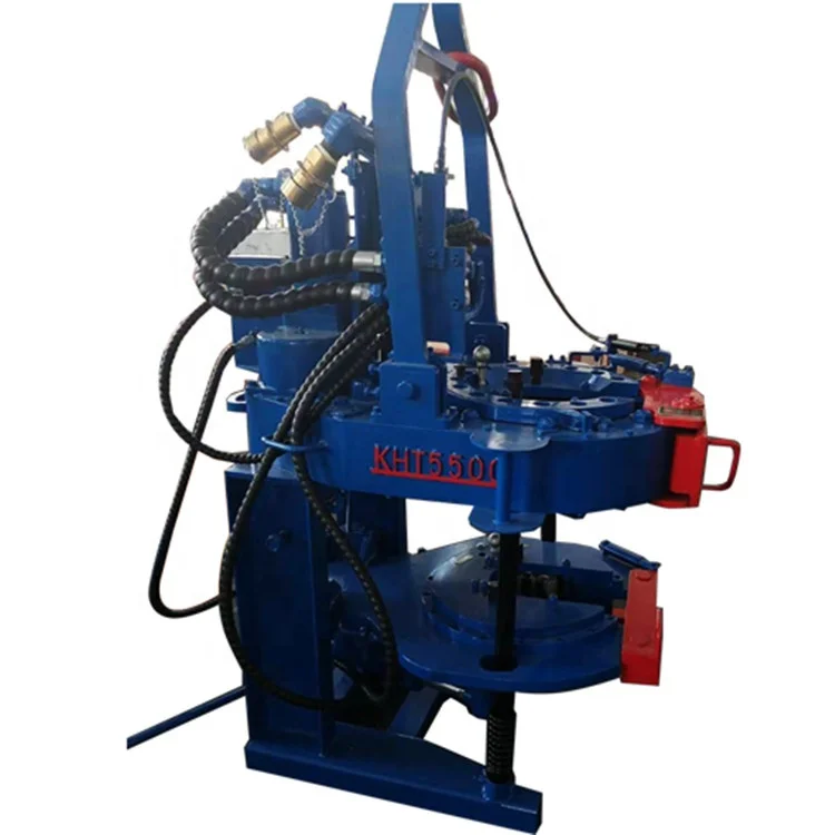
In order to facilitate the connection and disconnection of lengths of well tubing and in order to apply the desired torque to the connections between lengths of well tubing, a power tong device is often used. The use of the power tong device permits the connections between the well tubing to be made up in compliance with the industry standard or tubing torque specifications, such as the American Petroleum Institute (“API”) specifications.
The power tong device typically operates by gripping two adjacent lengths of well tubing and applying torque as may be required either to make up or break the connection between them. More particularly, the power tong device typically operates by gripping above and below the connection between the adjacent lengths of well tubing and applying opposing rotational forces to the lengths of well tubing in order to connect or disconnect the lengths of well tubing.
In this regard, the power tong device may typically include a powered tong, a back-up tong and a support structure or support system for supporting and positioning the tongs relative to each other during use. The powered tong is typically positioned above the back-up tong and grips and rotates the length of well tubing above the connection while the back-up tong grips the length of well tubing below the connection in order to resist the rotation of the lower length of well tubing relative to the upper length of well tubing.
Both the powered tong and the back-up tong typically include one or more clamps or jaws for gripping the lengths of well tubing. The powered tong and the back-up tong are typically configured or shaped to be compatible with well tubing and couplers so that the well tubing and the couplers are not crushed or damaged when gripped.
In particular, threaded connectors and couplers are particularly susceptible to crushing or damage during use of the power tong device. Therefore, the powered tong and the back-up tong must be placed with care on the lengths of well tubing, preferably out of contact with the connectors and preferably out of contact with any coupler which may be present. In the case of EUE well tubing, the powered tong and the back-up tong are also preferably placed out of contact with the upset ends of the well tubing so that the tongs can engage a relatively uniform cross-section of the well tubing.
The support structure of the power tong device is typically configured to maintain the powered tong and the back-up tong at a predetermined longitudinal distance or “gripping span” relative to each other. The gripping span is the clear distance between the tongs, which is typically the distance between the lower end of the powered tong and the upper end of the back-up tong. The gripping span of the power tong device is typically sufficiently large to enable the powered tong and the back-up tong to grip adjacent lengths of well tubing at locations which are spaced from the threaded connectors and any associated coupler, thereby maintaining the connection between the lengths of well tubing within the gripping span and avoiding damage to the connection by the power tong device. In the case of EUE well tubing, the gripping span of the power tong device is also typically sufficiently large to enable the tongs to grip adjacent lengths of well tubing at locations which are spaced from the upset ends of the lengths of well tubing, thereby maintaining the “upset length” of the connection within the gripping span.
A typical length of a threaded connector on the end of a length of a 3.5 inch size well tubing may be between about 2.5 inches (about 6.35 cm) and about 3 inches (about 7.62 cm).
The length of a threaded connection between lengths of well tubing may be defined by the combined lengths of the threaded connectors and/or by the length of a coupler which is used to complete the connection. A typical length of a threaded connection between lengths of 3.5 inch size well tubing may be between about 5 inches (about 12.7 cm) and about 6 inches (about 15.24 cm).
In the case of EUE well tubing, a typical length of an upset end of a length of 3.5 inch size EUE well tubing may be between about 3.5 inches (about 8.89 cm) and about 4.5 inches (about 11.43 cm) so that the total upset length of a threaded connection between two lengths of 3 5 inch size EUE well tubing may be between about 7 inches (about 17 78 cm) and about 9 inches (about 22.86 cm).
In some typical power tong devices, the gripping span between the powered tong and the back-up tong may be about 11 inches (about 27 94 cm) As a result, a power tong device is typically capable of connecting and disconnecting lengths of 3.5 inch size and smaller well tubing without damaging the threaded connections between them In the case of EUE well tubing, a power tong device is also typically capable of gripping the lengths of 3.5 inch size and smaller well tubing at locations which are spaced from the upset ends.
The tongs of the power tong device typically provide a maximum clearance diameter for objects passing through the tongs The maximum clearance diameter of the tongs is the maximum radial or transverse dimension to which the tongs can be expanded The maximum clearance diameter of the tongs is typically sufficiently large to enable connected lengths of well tubing, including associated couplers, to pass longitudinally through the tongs to facilitate assembly or disassembly of a tubing string.
A typical outside diameter of a length of 3.5 inch size well tubing may be about 3 5 inches (about 8 89 cm) and a typical outside diameter of a coupler which may be used to complete a threaded connection between two lengths of 3 5 inch size well tubing may be about 4.5 inches (about 11.43 cm) In some typical power tong devices, the maximum clearance diameter of the tongs may be about 5 inches (about 12.7 cm) or about 6 inches (about 15.24 cm) As a result, connected lengths of 3 5 inch size and smaller well tubing are typically capable of being passed longitudinally through the tongs of a power tong device
The tongs of the power tong device have a tong length The tong length of a tong is the longitudinal length of the surface of the tong which grips the lengths of well tubing A typical tong length for the tongs of a power tong device is about 4 inches (about 10 16 cm) The substantially uniform external surface of a typical length of well tubing (other than the upset ends of an EUE well tubing) constitutes a suitable gripping surface to be gripped by the tongs of a power tong device
Examples of various power tong devices are provided by U.S. Pat. No. 7,121,166 issued Oct. 17, 2006 to Drzewiecki, U.S. Pat. No. 7,000,503 issued Feb. 21, 2006 to Dagenais, et al., U.S. Pat. No. 6,082,224 issued Jul. 4, 2000 to McDaniels, et al., U.S. Pat. No. 4,631,987 issued Dec. 30, 1986 to Buck and U.S. Pat. No. 4,084,453 issued Apr. 18, 1978 to Eckel.
In addition to lengths of well tubing, a tubing string may include one or more well tools. Well tools may typically be connected at the ends of the tubing string or may be interposed in the tubing string between lengths of well tubing and/or other well tools. It may therefore be necessary to connect such well tools into the tubing string or to disconnect such well tools from the tubing string.
For instance, there may be a need to connect or disconnect a hanger, often referred to as a “tubing hanger”, to an upper end of the tubing string in order to support the tubing string in a wellbore. Further, there may be a need to connect or disconnect a drain, often referred to as a “tubing drain”, within a tubing string between lengths of well tubing to permit the draining of fluid from within the tubing string when required.
In order to facilitate connection into the tubing string, a well tool may be comprised of one or more connectors which are compatible with the connectors on the lengths of well tubing. For example, a typical well tool may be comprised of one or more threaded connectors such as a threaded pin connector and/or a threaded box connector. As with the threaded connections between lengths of well tubing, it is often desirable for a specified amount of torque to be applied to a threaded connection between a well tool and a length of well tubing.
A typical well tool of the type which may typically be connected into a tubing string may be configured in a manner which renders difficult or impossible the safe and effective use of a power tong device to make up or break the connection between the well tool and a length of well tubing.
More particularly, the well tool may be comprised of components and/or structures which do not enable a power tong device to safely and effectively grip both the well tool and the length of well tubing in a manner which does not risk damage to either the well tool or the length of well tubing.
As a first example, such components and/or structures may not accommodate the gripping span of the power tong device because the presence of such components and/or structures lengthens the distance between an appropriate gripping surface on the well tool and the end of the well tool which is to be connected with the length of well tubing. As a result, the gripping span of the power tong device may be insufficient to enable the connection between the well tool and the length of well tubing to be located within the gripping span. In the case of EUE well tubing and well tools having EUE connectors, the gripping span of the power tong device may be insufficient to enable the upset length of the connection between the well tool and the length of well tubing to be located within the gripping span.
As a second example, such components and/or structures may not accommodate the maximum clearance diameter of the tongs of the power tong device because the presence of such components and/or structures results in the radial or transverse dimension of the well tool being greater than the maximum clearance diameter.
In cases where the configuration of a well tool renders the use of a power tong device to be impractical in order to connect the well tool into or disconnect the well tool from a tubing string, it is common to make up or break a connection between the well tool and a length of well tubing manually. It may, however, be difficult to provide a suitable amount of torque without the use of a power tong device. This frequently results in the use of loctite or other adhesives to complete connections, which connections may then be very difficult to break when necessary. Safety at the wellsite may also be compromised if a power tong device cannot be used.
There is therefore a need in the industry for a well tool which is adapted to be connected with and disconnected from a well tubing using a power tong device. There is a particular need in the industry for a tubing hanger for supporting a tubing string within a wellbore which is adapted to be connected with and disconnected from a well tubing using a power tong device. There is also a particular need in the industry for a tubing drain which permits fluid to be drained from a tubing string and which is adapted to be connected with and disconnected from a well tubing using a power tong device.
Examples of tubing hangers which are known in the art are provided by Canadian Patent Application No. 2,215,755 published on Aug. 7, 1998 by McPhie et. al., U.S. Pat. No. 1,931,024 issued Oct. 17, 1933 to Howard, U.S. Pat. No. 2,148,327 issued Feb. 21, 1939 to Smith et. al., U.S. Pat. No. 2,274,477 issued Aug. 24, 1939 to Howard et. al., U.S. Pat. No. 3,001,803 issued May 7, 1956 to Watts et. al., U.S. Pat. No. 4,690,221 issued Sep. 1, 1987 to Ritter, Jr. and U.S. Pat. No. 6,019,175 issued Feb. 1, 2000 to Haynes.
Examples of tubing drains which are known in the art are provided by U.S. Pat. No. 3,552,412 issued Jan. 5, 1971 to Hagar et. al., U.S. Pat. No. 3,981,360 issued Sep. 21, 1976 to Marathe, U.S. Pat. No. 4,286,662 issued Sep. 1, 1981 to Page, Jr., U.S. Pat. No. 6,591,915 issued Jul. 15, 2003 to Burris et. al., U.S. Pat. No. 6,752,212 issued Jun. 22, 2004 to Burris et. al. and U.S. Publication 2004/0216867 A1 published on Nov. 4, 2004 by Burris et. al.
None of these examples are specifically directed at providing a well tool which is configured to be connected with or disconnected from a well tubing using a power tong device.
References in this document to orientations, to operating parameters, to ranges, to lower limits of ranges, and to upper limits of ranges are not intended to provide strict boundaries for the scope of the invention, but should be construed to mean “approximately” or “about” or “substantially”, within the scope of the teachings of this document, unless expressly stated otherwise.
The ability to use the power tong device to facilitate the connection between the well tool and the well tubing may permit the connection to be made up in compliance with API tubing torque specifications. In addition, the ability to use the power tong device may avoid the need to use pipe wrenches, snipes, winch lines or other manual tools or mechanism for providing the connection and disconnection between the well tool and the well tubing. Thus, the configuration of the well tool and the ability to utilize the power tong device may enhance the safety of personnel making and breaking the connections.
The well tool may be comprised of or may consist essentially of any structure, device or apparatus of the type which may be connected with a well tubing. In some embodiments, the well tool may be connected with one or more lengths of well tubing so that the well tool is a component of a tubing string. The tubing string may have a proximal end which is adapted to be positioned at or near a ground surface, and the tubing string may have a distal end which is adapted to be positioned within a wellbore. The well tool may be connected at an end of a tubing string or the well tool may be interposed between lengths of well tubing and/or other well tools.
By way of non-limiting examples, the well tool may be comprised of or may consist essentially of a pump, a packer, a measuring instrument, a valve, a testing tool, a tubing hanger, a strainer, or a tubing drain.
In some exemplary embodiments described herein, the well tool may be comprised of or may consist essentially of a tubing hanger. In some exemplary embodiments described herein, the well tool may be comprised of or may consist essentially of a tubing drain.
The well tool is adapted to be connected with and disconnected from a well tubing using a power tong device as a result of the configuration of the well tool. The configuration of the well tool provides an amount of compatibility between the well tool and the power tong device.
The power tong device upon which the configuration of the well tool of the invention is based is of a type which has a pair of tongs, a gripping span between the pair of tongs, and a maximum clearance diameter for an object passing through the tongs.
In an exemplary aspect, the invention is a well tool adapted to be connected with and disconnected from a well tubing using a power tong device of the type having a pair of tongs, a gripping span between the pair of tongs, and a maximum clearance diameter for an object passing through the tongs, the well tool comprising:
a tubular mandrel having a first mandrel end, a second mandrel end, an external mandrel surface, a maximum mandrel diameter, and defining a mandrel bore, wherein the maximum mandrel diameter is no greater than the maximum clearance diameter, wherein the tubular mandrel is comprised of a first mandrel connector located at the first mandrel end which is adapted for connecting the tubular mandrel with a first well tubing in order to provide a first connection between the tubular mandrel and the first well tubing, wherein the external mandrel surface defines a tong gripping surface which is located between the first mandrel end and the second mandrel end, and wherein the tubular mandrel is configured so that when the tong gripping surface and the first well tubing are gripped by the power tong device in order to connect the tubular mandrel with the first well tubing the first connection is located within the gripping span.
In some embodiments, the first connection may be comprised of or may consist essentially of a first threaded connection so that the first mandrel connector is comprised of a threaded connector. In some embodiments, the first mandrel connector may be comprised of an external upset end (EUE) connector. In some embodiments, the first mandrel connector may be comprised of a pin connector. In some embodiments, the first mandrel connector may be comprised of a box connector. In some embodiments, the first mandrel connector may be comprised of an external upset end (EUE) pin connector.
In some embodiments, each of the tongs in the pair of tongs of the power tong device may have a tong length, the tong gripping surface may have a gripping surface length, and the gripping surface length may be greater than the tong length.
In some embodiments, the maximum clearance diameter of the power tong device with which the well tool is intended to be used is about 6 inches (about 15.24 cm) so that the maximum mandrel diameter is no greater than about 6 inches (about 15.24 cm).
In some embodiments, the maximum clearance diameter of the power tong device with which the well tool is intended to be used is about 5 inches (about 12.7 cm) so that the maximum mandrel diameter is no greater than about 5 inches (about 12.7 cm).
A length of well tubing and/or a well tool may be comprised of a connector at each end. In some cases, the connectors on the ends of a length of well tubing or well tool may have a length which is between about 2.5 inches (about 6.35 cm) and about 3 inches (about 7.62 cm).
The tong gripping surface may have a first gripping surface end and a second gripping surface end, wherein the first gripping surface end is between the first mandrel end and the second gripping surface end, and wherein the second gripping surface end is between the second mandrel end and the first gripping surface end. The tubular mandrel may have a first span length which is between the first gripping surface end and the first mandrel end, and the tubular mandrel may have a second span length which is between the second gripping surface end and the second mandrel end.
In configuring the well tool of the invention, the first span length and/or the second span length is limited by the gripping span of the power tong device. In configuring the well tool of the invention, the first span length and/or the second span length may also be limited by the length of the connectors on the well tubing and/or other well tools with which the well tool of the invention will be connected, by the length of a coupler which may be used to connect the well tool of the invention with well tubing and/or other well tools, and/or by the length of the upset ends on the well tubing and/or other well tools with which the well tool of the invention will be connected.
In some embodiments, the well tool of the invention may be configured so that the first span length is no greater than the difference between the gripping span of the power tong device and the length of the connector on the well tubing or other well tool with which the well tool of the invention will be connected. In some embodiments, the well tool of the invention may be configured so that the second span length is no greater than the difference between the gripping span of the power tong device and the length of the connector on the well tubing or other well tool with which the well tool of the invention will be connected.
In some embodiments, the well tool of the invention may be configured so that the first span length is no greater than the difference between the gripping span of the power tong device and one half of the length of a coupler which will be used to complete the connection between the well tool of the invention and a length of well tubing or other well tool. In some embodiments, the well tool of the invention may be configured so that the second span length is no greater than the difference between the gripping span of the power tong device and one half of the length of a coupler which will be used to complete the connection between the well tool of the invention and a length of well tubing or other well tool.
In some embodiments, the well tool of the invention may be configured so that the first span length is no greater than the difference between the gripping span of the power tong device and the length of the upset end on the well tubing or other well tool with which the well tool of the invention will be connected. In some embodiments, the well tool of the invention may be configured so that the second span length is no greater than the difference between the gripping span of the power tong device and the length of the upset end on the well tubing or other well tool with which the well tool of the invention will be connected.
In some embodiments, the gripping span of the power tong device with which the well tool of the invention may be used may be about 11 inches (about 27.94 cm).
In some embodiments in which the gripping span of the power tong device may be about 11 inches (about 27.94 cm) and the well tool of the invention is configured to be used with 3.5 inch size or smaller well tubing, the well tool of the invention may be configured so that the first span length is no greater than about 8 inches (about 20.32 cm) and/or so that the second span length is no greater than about 8 inches (about 20.32 cm), so that the connection between the well tool of the invention and a length of well tubing may be located within the gripping span.
In some embodiments in which the gripping span of the power tong device may be about 11 inches (about 27.94 cm) and the well tool of the invention is configured to be used with 3.5 inch size or smaller well tubing, the well tool of the invention may be configured so that the first span length is no greater than about 7 inches (about 17.78 cm) and/or so that the second span length is no greater than about 7 inches (about 17.78 cm), so that both the connection between the well tool of the invention and a length of well tubing and the upset end of the length of well tubing may be located within the gripping span.
In some embodiments in which the gripping span of the power tong device may be about 11 inches and the well tool of the invention is configured to be used with 3.5 inch size or smaller well tubing, the well tool of the invention may be configured so that the first span length is no greater than about 6.5 inches (about 16.51 cm) and/or so that the second span length is no greater than about 6.5 inches (about 16.51 cm), so that both the connection between the well tool of the invention and a length of well tubing and the upset end of the length of well tubing may be located within the gripping span.
As indicated, in some embodiments, the well tool of the invention is configured to be used with 3.5 inch size or smaller well tubing, such as 2⅜ inch size well tubing or 2⅞ inch size well tubing. In some embodiments, this configuration may also be used with 4.5 inch size well tubing. However, if required, some of the dimensions of the well tool may be adjusted in accordance with the principles discussed herein.
In some embodiments, the well tool may be comprised of or may consist essentially of a tubing hanger which may be directly or indirectly connected with one or more lengths of well tubing. The tubing hanger may be adapted to be connected as a component of a tubing string in order to provide an interface between the tubing string and a well for supporting the tubing string in the well. In some embodiments, the tubing hanger may be connected into a tubing string at or near a proximal end of the tubing string.
The tubing hanger may be adapted to engage a structure which is located at or near a ground surface in order to enable the tubing string to be supported in the well. In some embodiments, the structure may be comprised of a tubing head so that the tubing hanger may be adapted to engage the tubing head in order to enable the tubing string to be supported in the well.
In some embodiments in which the well tool may be comprised of or may consist essentially of a tubing hanger, the tubular mandrel may be further comprised of a second mandrel connector, and the well tool may further comprise:
a tubular shell having a first shell end, a second shell end, and defining a shell bore for receiving the tubular mandrel therein, wherein the tubular shell has an external shell surface, wherein the external shell surface defines a tubing head engagement surface which is adapted to engage a tubing head, wherein the tubular shell is comprised of a shell connector for connecting with the second mandrel connector in order to provide a second connection between the tubular mandrel and the tubular shell, and wherein the first mandrel end and the tong gripping surface extend from the first shell end when the tubular mandrel is received in the shell bore and the tubular mandrel is connected with the tubular shell.
In some embodiments in which the well tool may be comprised of or may consist essentially of a tubing hanger, the well tool may be further comprised of a locking mechanism for maintaining the tubular mandrel and the tubular shell in a desired relative position when the tubular mandrel and the tubular shell are connected with each other. The locking mechanism may be comprised of any structure, device or apparatus which is suitable for maintaining the tubular mandrel and the tubular shell in the desired relative position.
In some embodiments, the locking mechanism may be comprised of a recess associated with one of the tubular mandrel and the tubular shell and a lug associated with the other of the tubular mandrel and the tubular shell. The lug may be movable into engagement with the recess when the tubular mandrel and the tubular shell are connected with each other at a desired relative position in order to maintain the tubular mandrel and the tubular shell at the desired relative position.
In some embodiments, the lug may be comprised of a set screw threadably associated with the tubular shell, the recess may be associated with the tubular mandrel, and the set screw may be movable into engagement with the recess in order to maintain the tubular mandrel and the tubular shell at the desired relative position.
In some embodiments in which the well tool may be comprised of or may consist essentially of a tubing hanger, the second connection may be comprised of or may consist essentially of a second threaded connection so that the second mandrel connector and the shell connector are comprised of threaded connectors. In some embodiments, the second mandrel connector may be comprised of a pin connector which is defined by the external mandrel surface. In some embodiments, the shell connector may be comprised of a box connector which is defined by the shell bore.
In some embodiments in which the well tool may be comprised of or may consist essentially of a tubing hanger, the first threaded connection and the second threaded connection may be threaded in opposite directions. In some embodiments, the second threaded connection may be threaded in a left handed direction.
In some embodiments in which the well tool may be comprised of or may consist essentially of a tubing hanger, the well tool may be further comprised of a shell seal device associated with the external shell surface, for providing a seal between the tubular shell and the tubing head. The shell seal device may be comprised of any structure, device or apparatus which is suitable for providing the seal between the tubular shell and the tubing head.
In some embodiments, the shell seal device may be comprised of at least one O-ring type seal and the external shell surface may define at least one corresponding O-ring groove for containing the O-ring type seal or seals.
In some embodiments in which the well tool may be comprised of or may consist essentially of a tubing hanger, the well tool may be further comprised of a mandrel seal device associated with at least one of the external mandrel surface and the shell bore, for providing a seal between the tubular mandrel and the tubular shell. The mandrel seal device may be comprised of any structure, device or apparatus which is suitable for providing the seal between the tubular mandrel and the tubular shell.
In some embodiments, the mandrel seal device may be comprised of at least one O-ring type seal and the external mandrel surface and/or the shell bore may define at least one corresponding O-ring groove for containing the O-ring type seal or seals. In some embodiments, the external mandrel surface may define the at least one corresponding O-ring groove.
In some embodiments in which the well tool may be comprised of or may consist essentially of a tubing hanger, the tubular mandrel may be further comprised of a third mandrel connector which is adapted for connecting the tubular mandrel with a lifting member in order to provide a third connection between the tubular mandrel and the lifting member. In some embodiments, the third mandrel connector may be located at or adjacent to the second mandrel end.
In some embodiments, the third connection may be comprised of a third threaded connection so that the third mandrel connector is comprised of a threaded connector. In some embodiments, the third mandrel connector may be defined by the mandrel bore. In some embodiments, the third mandrel connector may be comprised of a box connector. In some embodiments, the third mandrel connector may be comprised of an external upset end (EUE) box connector.
In some embodiments, the well tool may be comprised of or may consist essentially of a tubing drain which may be directly or indirectly connected with one or more lengths of well tubing. The tubing drain may be adapted to be connected as a component of a tubing string in order to provide a capability to drain the tubing string. In some embodiments, the tubing drain may be adapted to be connected into a tubing string at or near a distal end of the tubing string.
The tubing drain may be comprised of a drain and a drain closing device. The drain closing device may be arranged to close the drain. The drain closing device may be actuatable to open the drain.
In some embodiments in which the well tool may be comprised of or may consist essentially of a tubing drain, the tubular mandrel may be further comprised of a second mandrel connector located at the second mandrel end which is adapted for connecting the tubular mandrel with a second well tubing in order to provide a second connection between the tubular mandrel and the second well tubing, the tubular mandrel may be configured so that when the tong gripping surface and the second well tubing are gripped by the power tong device in order to connect the tubular mandrel with the second well tubing the second connection is located within the gripping span, the tubular mandrel may define a drain extending between the external mandrel surface and the mandrel bore, and the well tool may further comprise:
(b) an actuatable drain closing device, wherein the drain closing device is arranged to close the drain, and wherein the drain closing device is actuatable to open the drain.
The drain closing device may be comprised of any structure, device or apparatus which is suitable for closing the drain. The drain closing device may be actuated to open the drain in any suitable manner. In some embodiments in which the well tool may be comprised of or may consist essentially of a tubing drain, the drain closing device may be actuatable to open the drain by providing an actuating pressure in the mandrel bore.
In some embodiments, the drain closing device may be comprised of a burst plug and the burst plug may be configured to rupture to open the drain when the actuating pressure is provided in the mandrel bore.
In some embodiments, the drain closing device may be comprised of a slidable sleeve. The slidable sleeve may surround the tubular mandrel. The slidable sleeve may cover the drain in order to close the drain. The slidable sleeve may be slidable relative to the tubular mandrel in order to uncover the drain. The slidable sleeve may be slidable to uncover the drain when the actuating pressure is provided in the mandrel bore. The actuating pressure may exert an actuating force on the slidable sleeve which causes the slidable sleeve to slide to uncover the drain. One or more shear members may connect the slidable sleeve with the tubular mandrel, and the actuating force may cause the shear members to shear in order to permit the slidable sleeve to slide to uncover the drain. The tubing hanger may be further comprised of a sleeve seal device for providing a seal between the external mandrel surface and the slidable sleeve.
In some embodiments, the drain may be comprised of a single drain port. In some embodiments, the drain may be comprised of a plurality of drain ports. In some embodiments, the drain may be comprised of a plurality of drain ports which are circumferentially spaced around the tubular mandrel.
A drain port or a plurality of drain ports may have a major dimension and a minor dimension. The major dimension may be larger than the minor dimension. The drain port or the plurality of drain ports may be arranged so that the minor dimension extends in a direction which is substantially parallel with a longitudinal axis of the tubing drain which extends between the first mandrel end and the second mandrel end.
In some embodiments in which the well tool may be comprised of or may consist essentially of a tubing drain, the second connection may be comprised of or may consist essentially of a second threaded connection so that the second mandrel connector is comprised of a threaded connector. In some embodiments, the second mandrel connector may be comprised of an external upset end (EUE) connector. In some embodiments, the second mandrel connector may be comprised of a pin connector. In some embodiments, the second mandrel connector may be comprised of a box connector. In some embodiments, the second mandrel connector may be comprised of an external upset end (EUE) pin connector.
FIG. 2 is a longitudinal sectional view of an embodiment of a well tool adapted to be connected and disconnected from a well tubing using a power tong device of the type shown in FIG. 1, wherein the well tool is a tubing hanger and wherein the well tool is comprised of a tubular mandrel and a tubular shell;
FIG. 5 is side view of the tubing hanger shown in FIG. 2 connected with a first well tubing and showing a lifting member for use with the tubing hanger;
FIG. 6 is a longitudinal sectional view of an embodiment of a well tool adapted to be connected and disconnected from a well tubing using a power tong device of the type shown in FIG. 1, wherein the well tool is a tubing drain, wherein the well tool is comprised of a tubular mandrel and an actuatable drain closing device and wherein the drain closing device is comprised of a slidable sleeve;
FIG. 10 is a side view of an embodiment of a well tool adapted to be connected and disconnected from a well tubing using a power tong device of the type shown in FIG. 1, wherein the well tool is a tubing drain, wherein the well tool is comprised of a tubular mandrel and an actuatable drain closing device and wherein the drain closing device is comprised of a burst plug.
Referring to FIGS. 2-10, a well tool (20) is provided which is adapted to be connected and disconnected from a well tubing using a power tong device (22) of the type shown in FIG. 1.
Referring to FIG. 1, the power tong device (22) is shown being utilized for the connection and disconnection of adjacent lengths or sections of well tubing (24), particularly 3.5 inch size EUE well tubing, wherein the well tubing provides a connector (26) at each end thereof. Referring to FIG. 5, a first well tubing (28), having a connector (26) at an end thereof, is shown connected with an exemplary embodiment of the well tool (20). Referring to FIG. 9, the first well tubing (28) and a second well tubing (30), also having a connector (26) at and end thereof, are shown connected with a further exemplary embodiment of the well tool (20). In these embodiments, the first and second well tubing (28, 30) may each be a length of 3.5 inch size well tubing.
In this exemplary embodiment, the well tool (20) is configured for connection with 3.5 inch size well tubing (28, 30). However, the well tool (20) may also be configured for connection with smaller size well tubing (28, 30), such as 2⅜ inch size well tubing or 2⅞ inch size well tubing, or larger size well tubing (28, 30), such as 4.5 inch size well tubing. If required, some of the dimensions of the well tool (20) may be adjusted in accordance with the general principles and guidelines discussed herein.
Compatible connectors (26) are provided at each end of the first and second well tubing (28, 30) to permit their connection to adjacent ends of other lengths of well tubing (24), as well as to permit their connection to the adjacent ends of the well tool (20) as described further below. In some embodiments, the connectors (26) are comprised of threaded connectors. In this instance, the connections between the first and second well tubing (28, 30) and the well tool (20) are comprised of threaded connections.
In some instances, the well tool (20) may be directly connected with and disconnected from the adjacent first well tubing (28) and/or second well tubing (30) by complementary threaded pin and box connectors at their ends. However, in some other instances, similar threaded pin or box connectors may be provided between adjacent ends of the well tubing (28, 30) and the well tool (20), and the connection may be completed by a collar or by some other coupler interposed therebetween. For instance, as shown in the exemplary embodiments of FIGS. 5 and 9, similar threaded pin connectors at adjacent ends of the well tubing (28, 30) and the well tool (20) are connected or fastened together by a compatible threaded box coupler (32).
The well tool (20) of the within invention is adapted so that a power tong device (22) of the type shown in FIG. 1 may be used to facilitate the connection and disconnection of adjacent threaded ends of the first well tubing (28) and/or the second well tubing (30) with the well tool (20) and to apply a desired amount of torque to the threaded connection therebetween. Further, the ability to use the power tong device (22) to facilitate the connections between the well tool (20) and the well tubing (28, 30) permits the connections to be made up in compliance with the industry standard for tubing torque specifications, particularly API tubing specifications. Otherwise, without the ability to use the power tong device (22), the connections may only be capable of being provided manually to pipe wrench or similar specifications.
In addition to permitting a desired amount of torque to be applied to the threaded connections, the safety of personnel making and breaking the connections may also be enhanced by the ability to utilize the power tong device (22) with the well tool (20). Specifically, the connections and disconnections between the well tool (20) and well tubing (28, 30) may be made without the use of pipe wrenches, snipes, winch lines or other similar tools or mechanisms.
As shown in FIG. 1, the power tong device (22) includes a pair of tongs for gripping or engaging the well tool (20) and well tubing (24). Typically, the pair of tongs is comprised of a powered tong (34) positioned above a back-up tong (36). Further, the power tong device (22) includes a support structure (38) for supporting and positioning the tongs (34, 36) relative to each other during use. Typically, the powered tong (34) is provided to grip and rotate the structure or component above the connection, while the back-up tong (36) is provided to grip the structure or component below the connection.
For example, referring to the exemplary embodiments shown in FIGS. 5 and 9, with respect to the connection between the well tool (20) and the first well tubing (28), the powered tong (34) may be used to grip and rotate the well tool (20) above the connection, while the back-up tong (36) may be used to grip and resist the rotation of the first well tubing (28) below the connection Referring to FIG. 9, with respect to the connection between the second well tubing (30) and the well tool (20), the powered tong (34) may be used to grip and rotate the second well tubing (30) above the connection, while the back-up tong (36) may be used to grip and resist the rotation of the well tool (20) below the connection
Further, the powered tong (34) and the back-up tong (36) of the power tong device (22) define a gripping span (40) and a maximum clearance diameter (42) for an object passing through the tongs (34, 36) In addition, each of the tongs (34, 36) has a tong length (44) measured longitudinally between an upper end or uppermost edge (46) and a lower end or lowermost edge (48) of the tong (34, 36) In some typical power tong devices (22), the tong length (44) for each of the powered and back-up tongs (34, 36) is about 4 inches (about 10.16 cm).
The gripping span (40) between the powered and back-up tongs (34, 36) is the longitudinal distance between the tongs (34, 36) Specifically, the gripping span (40) is the distance from the lowermost edge (48) of the powered tong (34) and the uppermost edge (46) of the back-up tong (36) The support structure (38) of the power tong device (22) maintains the powered tong (34) and the back-up tong (36) at the predetermined longitudinal distance or gripping span (40) relative to each other
In some typical power tong devices (22) for use with 3.5 inch size well tubing (24), the gripping span (40) may be about 11 inches (about 27.94 cm) The well tool (20) of the within invention is adapted such that the well tool (20) may be connected and disconnected from the first well tubing (28) and/or second well tubing (30) using the power tong device (22) Thus, when the tongs (34, 36) grip the well tubing (28, 30) and the well tool (20) in the manner described above, the threaded connection is positioned within the gripping span (40) defined between the tongs (34, 36) Furthermore, the well tool (20) is adapted such that the tongs (34, 36) grip each of the well tubing (28, 30) and the well tool (20) at a location apart or away from the threaded connector ends/upset ends and coupler (32) in order to avoid causing any damage thereto during use of the power tong device (20).
The maximum clearance diameter (42) of the tongs (34, 36) is the maximum radial or transverse dimension to which the tongs (34, 36) can be expanded to permit an object to pass through the tongs (34, 36) In some typical power tong devices (22) for use with 3 5 inch size well tubing, the maximum clearance diameter of the tongs (34, 36) may be about 5 inches (about 12.7 cm) or about 6 inches (about 15.24 cm). As indicated, the well tool (20) of the within invention is adapted such that the well tool (20) may be connected and disconnected from the first or second well tubing (28, 30) using the power tong device (22). Thus, the well tool (20) is shaped or configured to permit the well tool (20) to pass through the maximum clearance diameter (42) of the tongs (34, 36).
Thus, referring to FIGS. 2, 4-6 and 8-10, in some embodiments of the invention, the well tool (20) is comprised of a tubular mandrel (50). The tubular mandrel (50) has a first mandrel end (52), an opposed second mandrel end (54) and a longitudinal axis (55) which extends between the first and second mandrel ends (52, 54). Further, the tubular mandrel (50) has an external mandrel surface (56) and defines a mandrel bore (58) extending between the first and second mandrel ends (52, 54). In some embodiments, the length of the tubular mandrel (50) longitudinally between the first and second mandrel ends (52, 54) is no greater than about 15 inches (38.1 cm).
In addition, the tubular mandrel (50) has a maximum mandrel diameter (60), being the maximum radial or transverse dimension of the tubular mandrel (50). In this regard, the maximum mandrel diameter (60) is no greater than the maximum clearance diameter (42) of the power tong device (22). Accordingly, in some embodiments, the maximum mandrel diameter (60) is no greater than about 6 inches (about 15.24 cm). In some other embodiments, the maximum mandrel diameter (60) is no greater than about 5 inches (about 12.7 cm).
Further, the tubular mandrel (50) is comprised of a first mandrel connector (62) located at the first mandrel end (52) which is adapted for connecting the tubular mandrel (50) with the first well tubing (28), as shown in FIGS. 5 and 9, in order to provide a first connection (64) between the tubular mandrel (50) and the first well tubing (28). In some embodiments, the first mandrel connector (62) is comprised of a pin connector defined by the external mandrel surface (56) at the first mandrel end (52). Further, in some embodiments, the first connection (64) is a first threaded connection. Thus, the first mandrel connector (62) may be a threaded connector, specifically a threaded pin connector. In particular, the first mandrel connector (62) may be an external upset end (“EUE”) pin connector.
The first well tubing (28) has a connector (26) compatible with the first mandrel connector (62) to provide the first connection (64). Thus, for instance, the connector (26) of the first well tubing (28) may be a compatible box connector, and in particular, a threaded box connector. However, in some exemplary embodiments, as shown in FIGS. 5 and 9, the connector (26) of the first well tubing (28) is comprised of a threaded pin connector. Thus, in order to provide the required connection between the threaded pin connector (26) of the first well tubing (28) and the threaded pin connector comprising the first mandrel connector (62), the first connection (64) may further include a compatible or complementary threaded box end coupler (32). Accordingly, in such embodiments, the first mandrel connector (62), the connector (26) of the first well tubing (28) and the coupler (32) may together provide the first connection (64).
Typically, based upon 3.5 inch size well tubing, the length of the connector (26) on the first well tubing (28) may be between about 2.5 inches (about 6.35 cm) and about 3 inches (about 7.62 cm). Similarly, in some embodiments, the length of the first mandrel connector (62) may be between about 2.5 inches (about 6.35 cm) and about 3 inches (about 7.62 cm). Thus, once connected by the coupler (32), the first connection (64) may be between about 5 inches (about 12.7 cm) and about 6 inches (about 15.24 cm) in length. If desired or required to enhance the first connection (64), a torque ring (not shown) or other mechanism for facilitating the connection may be positioned between the first mandrel connector (62) and the connector (26) on the first well tubing (28).
As well, the external mandrel surface (56) defines a tong gripping surface (66) located between the first mandrel end (52) and the second mandrel end (54). The tong gripping surface (66) has a first gripping surface end (68), an opposed second gripping surface end (70) and a gripping surface length (72) defined longitudinally between the first and second gripping surface ends (68, 70). The gripping surface length (72) is greater than the tong length (44) in order to permit one of the powered tong (34) and the back-up tong (34, 36) to engage the tong gripping surface (66) without causing damage to the tubular mandrel (50) when using the power tong device (22). Thus, the gripping surface length (72) may be greater than about 4 inches (about 10.16 cm). In some embodiments, the gripping surface length (82) is about 6 inches (15.24 cm).
As stated, the tong gripping surface (66) is provided for contact with one of the powered tong (34) and the back-up tong (36) when connecting or disconnecting the well tool (20) using the power tong device (22). Further, the tubular mandrel (50) is configured so that when the tong gripping surface (66) and the first well tubing (28) are gripped by the power tong device (22) in order to connect the tubular mandrel (50) of the well tool (20) with the first well tubing (28), the first connection (64) is located within the gripping span (40).
Specifically, in this embodiment, the powered tong (34) grips the tong gripping surface (66) on the tubular mandrel (50), while the back-up tong (36) grips the first well tubing (28) along the length thereof. The first connection (64) provided by the engagement of the first mandrel connector (62), the connector (26) of the first well tubing (28) and the coupler (32) is located within the gripping span (40).
Further, as indicated above, the tong gripping surface (66) has a first gripping surface end (68) and a second gripping surface end (70). As shown in FIGS. 2 and 6, the first gripping surface end (68) is positioned or located between the first mandrel end (52) and the second gripping surface end (70), while the second gripping surface end (70) is positioned or located between the second mandrel end (54) and the first gripping surface end (68).
Additionally, in some exemplary embodiments, the tubular mandrel (50) has a first span length (74) defined by the longitudinal distance, i.e. in the direction of the longitudinal axis (55) of the tubular mandrel (50), between the first gripping surface end (68) of the tong gripping surface (66) and the first mandrel end (52). In order to adapt the well tool (20) to permit its connection and disconnection from the first well tubing (28), as shown in FIGS. 5 and 9, the first span length (74) may be no greater than about 8 inches (20.32 cm). However, in some embodiments of the well tool (20), the first span length (74) may be no greater than about 7 inches (about 17.78 cm) or no greater than about 6.5 inches (about 16.51 cm).
Similarly, in some exemplary embodiments, the tubular mandrel (50) has a second span length (76) defined by the longitudinal distance between the second gripping surface end (70) of the tong gripping surface (66) and the second mandrel end (54). In order to adapt the well tool (20) to permit its connection and disconnection from the second well tubing (30), as shown in FIG. 9, the second span length (76) may be no greater than about 8 inches (20.32 cm). However, in some embodiments of the well tool (20), the second span length (76) may be no greater than about 7 inches (about 17.78 cm) or may be no greater than about 6.5 inches (about 16.51 cm).
In some exemplary embodiments of the well tool (20), the well tool (20) is a tubing hanger (78), as shown in FIGS. 2-5. The tubing hanger (78) is typically provided for supporting a tubing string comprised of one or more len


 8613371530291