
power tong dies quotation
When buying a power tong dies, you can also minimize your production costs in the future by standardizing some elements of the mold. This means that if you have multiple molded products, you can ask for standard lift bars, connection sizes and clamp slots across all your molds to make them easy to use.
Our huge network of mold shops on Alibaba.com are ready to help you find the right wholesale power tong dies for your products. Use the information available on the platform to decide on the perfect power pu dies that meet your requirements of quality and price. When starting a molded products manufacturing project, it starts with a dfm or design for manufacturing which is created by the mold making shop after analyzing your product design and is there to tell you how the mold is going to be made. After your approval, the mold will be made according to the mold shape.
If you are looking for distinct categories of power tong dies, Alibaba.com is the best place where you can find loads of them. These sturdy and optimum quality power tong dies are ideal for making a vast array of items ranging from normal household products and appliances to automotive and other commercial products too. These power tong dies are fully customizable and professional OEM products that are the best fit for any type of manufacturing plant. Buy these from the leading suppliers and wholesalers on the site. The plastic injection power tong dies available on the site are of export quality and they are made from sturdy materials such as plastic, metal, ABS, PE, PMMA, PC, POM, PBT, PP, PA66, PPO, PVC, PET, etc that are well known for their robust structures. The best part of using these power tong dies is the precision it offers while sh.

KET inserts and dies are manufactured from quality materials and precision-machined to exacting tolerances. They are heat-treated to industry standards to provide the best wear and resistance for the harshest of environments. The inner ductile core minimizes the shock of impact and torque.

Tong dies have come a long way since tongs became commonplace in the oilfields. Eckel has been at the forefront of this developing technology with the development of larger wrap-around type dies for many of its tong models. We offer coarse tooth design and fine tooth design depending on the application.
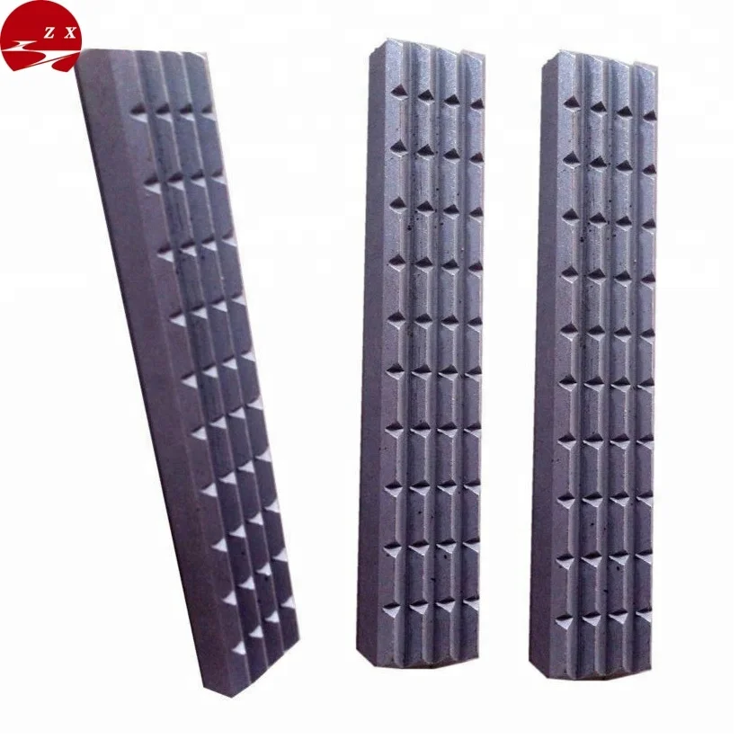
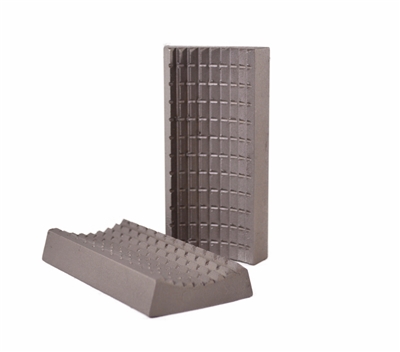
Rig Dies (Typically 1" and 1-1/4" wide) are available in coarse tooth die are typically used for casing and drill pipe where tool joint O.D. sizes vary from joint to joint. Also, Drill Pipe is also a harder steel and rig dies provide a more aggressive and better grip. Rig dies are available with the following surface areas:
Coated Contour True Grit® Dies: Used on chrome and fiberglass tubulars where reduced die penetration and die marking is greatly desired. For more information refer to the

Tong dies have come a long way since tongs became commonplace in the oilfields. Eckel has been at the forefront of this developing technology with the development of larger wrap-around type dies for many of its tong models. We offer coarse tooth design and fine tooth design depending on the application.
Wrap-Around Dies are considered the best choice for thinner wall tubulars where point loading is a concern. Wrap-Around Dies are symmetrically spaced from each other at all times insuring an equally distributed load on the tubular. Having a larger gripping surface area allows more teeth to come in contact with the tubular. Wrap-Around Dies come in any size to match tubing and casing tubulars and API coupling diameters. Wrap-Around dies are available with the following surface areas:
Coated True Grit® Dies: Used on chrome and fiberglass tubulars where reduced die penetration and die marking is greatly. For more information see the True Grit® Dies section.
Eckel offers contour type dies for tubing sizes on many of our tongs which use pivot heads. In addition to our contour dies, we provide A and S series wrap-around dies for our 13-3/8 and 20 Standard casing tongs, providing a larger gripping area and reducing pipe damage. Rig type dies are used extensively for 4-inches and above. Sliding heads with rig dies is the best choice when running drill pipe connections.
The KT13625 casing tong can handle tubulars as small as 3-1/2″ and as large as 13-5/8″ in diameter. Wraparound jaw and die technology for the two tong jaws is available. Tong can be mounted on either a CLINCHER® or a FARR hydraulic backup. Available with McCoy’s patented WinCatt® data acquisition and torque control system for the make-up of tubular connections.

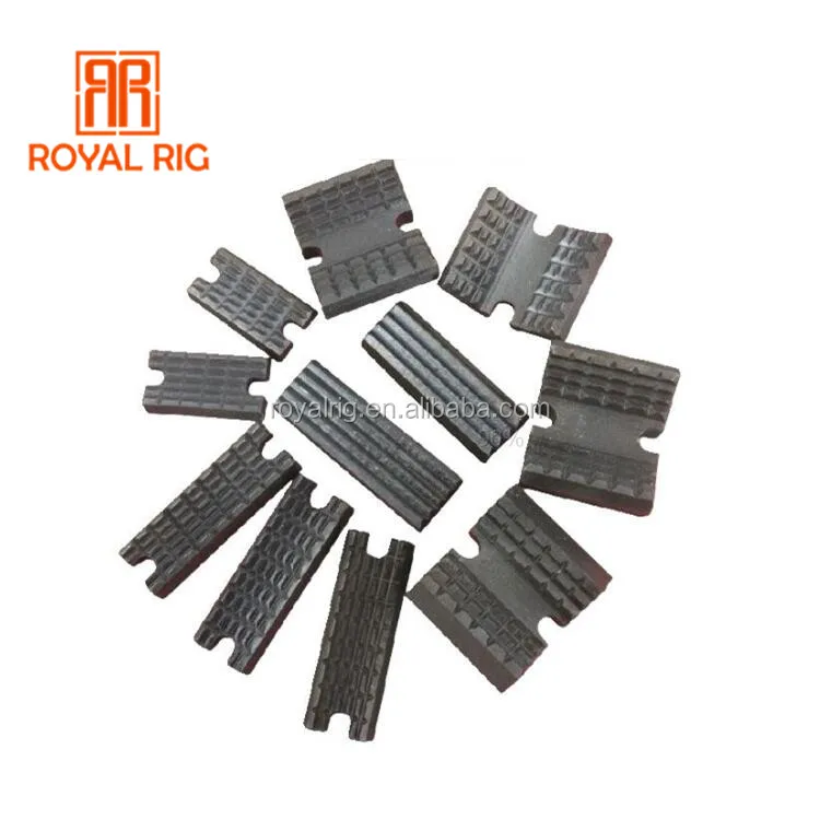
Keystone offers a full line of inserts and dies which include:elevator insertsfor all Slip Type Elevators;slip insertsfor drill collar, rotary, and casing slips; tubing and drill pipe tong dies; and coil tubing inserts for elevators, slips, and spiders. We also manufacturetong diesfor the ST-80 Iron Roughneck.
We manufacture our dies and inserts from quality materials and precision machine them to exacting tolerances. They are heat-treated to industry standards to provide the best wear and resistance for the harshest of environments.

Pan Industries manufactures all sizes and types of Tong Dies. Custom applications are always welcome at Pan Industries. Share any Reference part number, Dimensions, Photo, Drawing and get a instant quote. Pan Industries tong dies are made out of best quality of alloy steel. Teeth edges of Tong Dies are slightly rounded off to eliminate the teeth bite on drill…
While running in or pulling out tubular at oil rigs the joints (tool joints) are tightened or loosened with the help of manual tongs or power tongs. Dies are the principal element in the manual tongs and power tongs which carry out the job of gripping the tool joints, before torque application. (Rollers or chain are also used for gripping of tubulars while using pipe spinners)
Janki Oil Tools Jodhpur manufactures tong dies out of the best quality alloy steel. The dies are case hardened to the desired depth while leaving the inner portion (core) ductile. The hardened surface is highly resistant to wear and exhibits quality gripping of tool joints. The inner ductile core absorbs the shock of sudden impact and heavy torque. Teeth edges are slightly rounded off to eliminate the teeth bite on the drill pipe. The combined effect is an efficient operation in the long run. Janki made these dies meet OEM specifications.

Model XQ28/2.6 hydraulic power tong is an improved type of XYQ1.8 which is used to make up and break out sucker rod thread in Well Service. This product has the following features:
A. The structure is compact, concise and light. Master tong is driven by a low-speed large torque hydraulic motor that matches with a manual control valve. The backup tong is just like a spanner. The total weight is approximately equal to XYQ1.8.
B. The operating is briefness and convenience with high efficiency. Put the respondence size jaw set into master tong and the respondence size glutting into backup tong, turning the reset knob incorrect direction then can make up and break out sucker rod by operating manual control valve. Two speed, snapping at low speed, spinning at high speed.

The present invention relates to pipe tongs or power tongs used in the oil and gas industry to make-up and break-out sections of drill pipe and other tubular members having threaded connections. More particularly, the present invention relates to tong jaws comprising one or more dies which are rotatable. I. BACKGROUND OF THE INVENTION
Power tongs are often employed in the oil and gas industry to break-out or make-up threaded connections on tubular members (such as drill pipe, tubing, and casing). It is generally required that one tong grip and rotate one section of a tubular string and a second tong grip and hold stationary the other section of the tubular string. The tong which rotates the section of the tubular member is typically referred to as the power tong, while the tong which holds the other section of the tubular member stationary is typically referred to as the back-up tong. Examples of conventional power tongs can be seen in references such as U.S. Pat. Nos. 5,671,961, 5,702,139, and 5,819,604 to Buck, each of which is incorporated herein by reference in its entirety.
Power tongs typically have two or more jaws which are actuated to grip and release the tubular member. There are generally two types of jaws—pivoting jaws and sliding jaws. Both pivoting jaw and sliding jaw power tongs are well known in the art. An example of a pivoting jaw power tong can be seen in U.S. Pat. No. 4,350,062 to Farr et al., which is incorporated by reference herein. FIG. 1 illustrates the basic components of a typical pivoting jaw power tong 1. A tong body 2 encloses a ring gear 3 which has a cam surface 4. Positioned within ring gear 3 are the pivoting jaws 5. Pivoting jaws 5 are pivotally attached between an upper and lower tong cage plate (not shown) by pivot pin 7. A roller 6 on pivoting jaws 5 engages cam surface 4 on ring gear 3. As is well known in the art, the rotation of ring gear 3 causes different sections of cam surface 4 to either push roller 6 toward tubular member 100 (causing the jaws to grip the tubular member) or allow roller 6 to move away from tubular member 100 (causing the jaws to release the tubular member).
An example of a sliding jaw power tong may be seen in U.S. Pat. No. 5,435,213 to Buck, which is incorporated by reference herein in its entirety. A sliding jaw power tong has a tong body and ring gear structure similar to a pivoting jaw power tong, but the jaw is not pinned to the cage plates. The sliding jaw is moved radially toward the tubular by way of the ring gear"s cam surfaces acting on the sliding jaws" rollers. Sliding jaws could also include radially moving jaw arrangements such as seen in U.S. patent application Ser. No. 10/421,041, filed on Apr. 23, 2003 to Bangert, entitled Improved Tong Piston and Cylinder Assembly, which is incorporated herein in its entirety.
Actual contact with the tubular member is typically accomplished through the use of die inserts which are removably positioned in the power tong jaws. Typical die inserts have gripping surfaces which contain a number of ridges or teeth, or have alternative gripping surfaces such as those disclosed in U.S. Pat. No. 6,378,399 to Bangert, which is incorporated by reference herein in its entirety. When the jaws close upon the tubular member, the teeth firmly “bite” into the tubular member and prevent slippage when torque is applied. In most conventional tong jaw systems, the jaws are designed to grip a tubular member of a particular nominal diameter (or a limited range of nominal diameters) and the dies are in a fixed orientation relative to the jaw body. The dies are positioned on the jaw at an angle to maximize the contact between the face of the die and the surface of the tubular member. Because the diameters of tubular members are allowed to vary within certain tolerances, the exact diameter of the tubular member being gripped can vary, especially when dealing with large diameter tubular members. Particularly in the case of prior art pivoting jaw systems, differing diameters may prevent all of the dies from squarely engaging the surface of the tubular member and in extreme cases may completely prevent one or more of the dies from contacting the surface of the tubular member. II. BRIEF DESCRIPTION OF THE DRAWINGS
FIG. 3 cis a perspective view of a multiple piece sliding tong jaw comprising a rotatable die assembly comprising a die with an integrally formed rocker bar.
The following description of embodiments of the present invention refers to the accompanying figures. The term “power tong” as used herein refers to both power tongs for rotating tubular members and back-up power tongs for holding tubular members stationary against rotation.
In one embodiment, the invention comprises the pivoting power tong jaw 101 shown in FIG. 2. The jaw 101 comprises an upper plate 102, a lower plate 103, and three column members 104. Upper plate 102 and lower plate 103 are arranged horizontally, the former above the latter. Upper plate 102 and lower plate 103 each contain two column member slots 105 and one column member opening 106. In one aspect, upper 102 and lower 103 plates will be formed by a high speed, precision cutting process. Examples of high speed precision cutting processes would include laser cutting or water jet cutting, shear or punch press types of heavy metal fabrication techniques, and may include plasma torch cutting. Plasma torch cutting and flame torch cutting would generally not be considered precision cutting processes, and conventional milling would not be considered high speed, although these methods could be used in less preferred embodiments for producing the plates, as could casting processes. As illustrated in FIG. 2, each column member 104 is positioned vertically. Two column members 104 ahave die retaining grooves 107 formed in them for receiving and retaining dies 108. (An enlarged view of a column member 104 ais depicted in FIG. 6 c, which clearly shows die retaining groove 107.) Column members 104 ahaving die retaining grooves 107 are positioned between upper plate 102 and lower plate 103 such that each end of each of column members 104 afits into a corresponding column member slot 105. Column members 104 are welded into place, or secured by another common method (e.g., using bolts or screws). The third column member 104 bis also positioned between upper plate 102 and the lower plate 103. This column member 104 bdoes not have a die retaining groove 107 and has points 109 at each end which extend through column member openings 106 in upper plate 102 and lower plate 103, thereby stabilizing column member 104 b. This embodiment further comprises a roller 110 which, as noted above, engages the cam surface of the power tong"s ring gear as suggested by FIG. 1. Roller 110 is held in place with roller pin 111.
In another embodiment, shown in FIG. 5, the invention comprises a die assembly 124 comprising two dies 126 aand 126 b. This embodiment is used in large jaw systems where a single die does not provide a sufficiently long gripping surface. Die assembly 124 is prevented from sliding up and out of die retaining groove 107 by die face pins 127 which fit into face holes 125 in the top portion of die retaining groove 107 above die assembly 124. It will be understood that die face pins 127 could be substituted for die top pin 120 in the embodiment shown in FIG. 2 to prevent die 108 from sliding up and out of die retaining groove 107.
In other embodiments, the invention may be adapted for sliding power tong jaws such as those shown in FIG. 3. FIG. 3 ashows a solid sliding tong jaw 300, and FIGS. 3 band 3 cshow sliding tong jaws 301 and 315 formed from multiple pieces. Examples of jaws formed from multiple pieces can be seen in the U.S. patent application entitled “Tong Jaw and Method for Constructing the Tong Jaw,” Ser. No. 10/638,783 which is incorporated herein by reference in its entirety. Similar to the pivoting jaws described above, jaws 301 and 315 each comprise an upper plate 304, a lower plate 305, and two column members 302. Upper plate 304 and lower plate 305 are arranged horizontally, the former above the latter. The upper plate 304 and lower plate 305 contain column member slots 306 which allow column members 302 to connect upper plate 304 and lower plate 305. As illustrated in FIG. 3 b, column members 302 are positioned such that die inserts 307 face inwardly in an arcuate orientation corresponding approximately to the diameter of the tubular member to be gripped, thereby allowing both of the die inserts 307 to come into contact with the surface of the tubular member when the power tong jaw member 301 is in use. In the embodiment shown in FIG. 3 b, jaw 301 comprises a rocking bar 310 and rocking bar recess 311, which function as described above to allow die 307 to rock or rotate about the vertical axis defined by rocking bar 310. The embodiment shown in FIG. 3 ccomprises a die 307 which comprises an integral rocking bar 312 as described above.
16. The power tong of claim 15, wherein said die is positioned such that an end of said back of said die is capable of engaging said back of said die retaining groove, while the opposite end of said back of said die engages said front of said die retaining groove.


 8613371530291