
power tong equipment free sample

This invention is directed to apparatus and methods for aligning wellbore tubulars; and to power tongs used in making and breaking joints of tubular members such as wellbore casing and tubing; to parts thereof; including, but not limited to gripping elements, and methods of their use.
During the drilling of oil and gas wells and the production of materials therefrom, various operations require the connection and disconnection of successive lengths of threaded tubulars such as pipe, casing, or tubing. Tools known as tongs are used to "make" and "break" such connections. Certain known power tongs have a body, a rotary rotatably mounted in said body and at least one active jaw which, on rotation of the rotary is cammed against a pipe in the rotary and grips it for rotation with the rotary. In known arrangements the camming action is generated by a cam member which is bolted to the rotary and is shaped so that the active jaw is cammed against the pipe on rotation of the rotary relative to the active jaw in one sense and will be released on rotation of the rotary relative to the active jaw in the opposite sense.
With known tongs high torques are applied to tubulars due to combinations of factors such as thread sealing requirements, the presence of corrosion, the existence of distortion, and pipe size and weight. Both in the "make" direction of rotation when a shoulder is suddenly encountered, and in the "break" direction at initial engagement of the tong and disengagement of the threads high shock forces may arise; e.g., with a power-driven tong, in excess of 50,000 foot-pounds of torque may be exerted, while relatively small die elements on jaws of the tong engage the pipe with extremely high force loadings. Slippage occurs and pipe surfaces become marred, marked, indented, or otherwise damaged.
Dies for gripping jaws have been provided with multiple serrations, or penetration features, to provide the interference contact at the joint surface. Grip element penetration into the joint surface is limited and controlled. The distribution and balance of grip element energizing forces are critical factors in the design, development and evaluation of such tong mechanisms. Linkages, levers, wedges, and cams are used to balance force components. Grip elements, or dies, are accurately disposed within carrier bodies, or jaws, which span a circumferential segment of the joint surface.
Uneven die loading can cause excessive indentation, marring or damage to a tubular surface. Drag or braking devices are used in certain tongs to effect proper biting of the dies relative to the pipe. The head or other member supporting the dies is frictionally restrained to insure that the dies do not simply rotate with the rotary as the rotary is driven.
Other tongs use an endless belt, chain or flexible material loop for gripping a tubular. Such tongs are disclosed in U.S. Pat. Nos. 3,799,010; 3,906,820; 3,892,140; 4,079,640; 4,099,479; and 4,212,212. There are a variety of problems associated with certain of these tongs:
Jaw/die tongs and the belt/chain tongs are used with relatively hard and rigid metal tubulars such as casing and tubing. If these tongs are used with thick tubulars or tubulars made from relatively "softer" metals or from premium metals such as high alloy steels or low carbon steels or tubulars made from non-metal materials such as fiber glass, they often literally chew up the tubular. The use of strap wrenches is inadequate since the torque applied with such wrenches cannot be precisely controlled.
Certain tubulars are treated with a rust or corrosion resistant material or coating. If the coating is indented, gouged, or broken, its protective purpose is defeated. Producing enough force in a tong to join such tubulars while not injuring a protective coating presents a dilemma.
The present invention, in certain embodiments, discloses a power tong for joining tubulars so that marking of, indentation of, and surface injury to tubulars are reduced or eliminated. In one aspect a power tong is provided and a method of its use for handling tubulars coated with a corrosion-resistant material which should not be broken or penetrated. In one embodiment such a tong has one or more gripping jaws with gripping elements made of aluminum alloys, zinc, zinc alloys, aluminum, brass, bronze, cermet, plastic, fiberglass, metal alloys, or a combination thereof which present a smooth face (straight or curved) to a tubular without any teeth, pointed projections, or toothed dies. In one aspect the gripping elements are releasably connected directly to jaws. In another aspect the gripping elements are releasably connected to a jacket or holder which itself is releasably connected to a jaw.
In one aspect the cylinder(s) are powered by a small air-driven hydraulic pump with an hydraulic fluid reservoir mounted on a plate on the movable or fixed jaw. Air is supplied to activate a motor of the pump and the pump then provides hydraulic fluid to move a piston of the hydraulic cylinder(s). The motion of the cylinder moves the movable jaw on its roller to travel to a pre-load position on the cam. The cylinder applies pressure until the hydraulic pressure is released. A hydraulic fluid accumulator and a valve may be used to maintain hydraulic pressure at all times so that the cylinder(s) continuously maintain the desired load on the jaw until the air supply to the pump is removed.
In another aspect the cylinders are connected to a rotary of the tong or to any other member that rotates with the rotary rather than to a fixed jaw. Such a pre-load system may, according to this invention, be used with any tong including a tong that does use toothed dies.
In one embodiment the present invention discloses a gripping arrangement for a tong with a sheet of grit which is preferably bonded to a carrier plate. In another embodiment the gripping arrangement comprises a layer of flexible material having a smooth flat surface or a surface with ridges and valleys, for example in the fashion of the surface of a file. The flexible material, in one aspect, is metal, for example sheet aluminum, zinc, brass, bronze, zinc alloy, aluminum alloy, stainless steel, or steel having a thickness of about 1.5 mm. The layer of flexible material may be used in conjunction with a carrier plate or on its own. In a further embodiment the gripping arrangement may comprise a layer of perforate material one of both surfaces of which are preferably coated with grit to facilitate adhesion. The layer will typically be formed from metal having a thickness of about 1.5 mm. The layer may be used in conjunction with a carrier plate or used on its own. In yet another embodiment the gripping arrangement may comprise a layer of expanded mesh, e.g. metal mesh, which has been flattened. One or both surfaces of the expanded mesh may be coated with grit and the layer may be used in conjunction with a carrier plate or used on its own. The grit may comprise, for example, diamond dust, particles of silicon, zircon, tungsten carbide and mixtures thereof. The gripping arrangement may comprise end plates which are attached to the carrier plate. Preferably, the carrier plate is provided with side flanges for insertion into a jaw holder. The present invention also provides a jaw assembly fitted with a gripping arrangement in accordance with the present invention. Preferably, the jaw assembly includes a jaw holder having an arcuate recess which accommodates an arcuate pad of resilient elastomeric material which supports said gripping arrangement. Advantageously, at least one shim is provided which is disposed between said arcuate pad of resilient elastomeric material and said gripping arrangement. The shim will be flexible and generally from 0.5 mm to 1.0 mm thick and made from sheet metal. The present invention also provides a tong fitted with at least two such jaw.
In one embodiment the present invention discloses an apparatus for aligning tubulars and includes a guide on one of a power tong and a backup tong. In one embodiment the apparatus has a socket centralizer mounted on said one of said power tong and said backup tong. In one aspect, said one of said power tong and said backup tong is said power tong. In another embodiment, the apparatus includes a power tong and a backup tong, and the guide is mounted on the power tong and apparatus is provided to maintain the power tong and the backup tong in a certain juxtaposition during a stabbing operation. Preferably, said apparatus includes locating rods on one of the power tong and the backup tong and blocks shaped to receive at least the ends of the locating rods on the other of the power tong and the backup tong. Advantageously, the backup tong is provided with at least two prismatic jaw assemblies to locate the backup tong in fixed juxtaposition with respect to a tubular being gripped.
The present invention, in one aspect, provides a jaw unit for use in a tong, which jaw unit comprises a jaw holder and a jaw movable with respect to said jaw holder, characterized in that said jaw is slidably mounted on said jaw holder. Preferably, said jaw is slidable with respect to said jaw holder about an arcuate path. Advantageously, said jaw has a gripping surface which is substantially arcuate for gripping the surface of a tubular and the center of curvature of such arcuate path lies between the center of curvature of said grip ping surface and said arcuate path. The gripping surface may be a continuous surface or defined by several spaced apart gripping elements. Preferably, the center of curvature of said arcuate path lies between the center of curvature of said grip ping surface and said gripping surface. Advantageously, the center of curvature of said arcuate path is substantially midway between the center of curvature of said gripping surface and said gripping surface. Preferably, one of said jaw and said jaw holder is provided with an arcuate track which defines said arcuate path, and the other of said jaw and said jaw holder is slidably mounted in said arcuate track.
The present invention also provides a jaw assembly comprising two jaw units in accordance with the present invention. Preferably, said jaw units are mounted for pivotal movement about a common pivot shaft. Advantageously, said jaw assembly includes means which bias said jaw units apart. The present invention also provides a rotary fitted with a jaw unit in accordance with the present invention, a rotary fitted with a jaw assembly in accordance with the present invention, and a tong fitted with a rotary in accordance with the present invention.
One of the features of existing tongs is that their rotaries are difficult to furnish. Thus, routine maintenance usually involves dismantling the whole rotary, checking the parts and reassembling the whole. While this is a straightforward procedure in the clean conditions of a workshop it can be problematic when carried out in a muddy field, in sand or in snow. The present invention aims to help solve this problem and provides a rotary which comprises a top section, a bottom section, and a peripheral wall therebetween, characterized in that at least one of said top section and said bottom section is provided with an elongate slot which, when said rotary is in use, accommodates a pivot shaft on which a jaw assembly can be pivotally mounted.
Jaw holders and jaws for tongs are traditionally machined from a solid piece. This is a comparatively expensive procedure. The present invention proposes to make such parts from a stack of individually cut laminations.
Such methods and devices including a power tong with at least one jaw with at least one tubular gripping element having a smooth gripping surface (flat or curved) and, in one aspect, such an element which is flexible;
FIG. 2A is a perspective view of a tubular connection system according to the present invention. FIGS. 2B and 2C are perspective views of a casing tong of the system of FIG. 2A.
FIG. 5A shows schematically an initial position of elements of a tong system according to the present invention. FIG. 5B shows pre-loading on a pipe of the jaws of the system of FIG. 5A. FIG. 5C shows a tubular gripped with the system of FIG. 5A.
FIGS. 1A-1C show a typical prior art power tong that uses fixed jaws and a movable jaw to grip pipe for tubular disconnecting and connecting operations. An outer case houses a powered rotary to which the jaws are mounted. A cam surface of the rotary moves a movable (ACTIVE or MASTER) jaw into (and away from) gripping contact with a tubular, e.g. pipe. Each jaw has toothed gripping inserts to facilitate engagement with the surface of the tubular (see FIG. 1B). FIG. 1C shows the tong in an "OPEN" position in which the tubular is not gripped.
The tong shown in FIG. 1A is a Weatherford Model 14.5-50 High Torque Tong. The brochure "New ! Weatherford Model 14.5-50 High Torque Tong," (1991) and the manual entitled "Model 14.5-50 Hydraulic Power Tong Installation, Operation and Maintenance" (1993) are submitted herewith and incorporated herein fully by reference for all purposes. It is to be understood that the teachings of the present invention are applicable to any tong and any tong system that has one or more gripping elements or jaws and that the Model 14.5-50 tong is shown here for illustrative purposes and not by way of limitation of the scope of the present invention.
As shown in FIG. 2A a system 10 according to the present invention includes a power tong 100 according to the present invention which is like the tong of FIG. 1A but which also includes a unique jaw system 110 with inserts 150 on fixed jaws 120 and insert 152 on movable jaw 122 and at least one jaw pre-load assembly like that shown in FIG. 5A. The system 10 includes a free floating backup tong 12.
As shown in FIGS. 2B and 2C, rods 112 are connected to the movable jaw 122. The inserts 150 are on fixed jaws 120 and the insert 152 is on a movable jaw 122 (corresponding to the fixed jaws and active jaw, respectively, of the tong of FIG. 1A).
FIGS. 4A-4G illustrate an alternative jaw mounting system in which holders are interposed between jaw bodies and inserts. The holders protect the jaws from damage if the inserts wear down and a variety of different types and/or sizes of inserts may be used with and interchanged on a single holder. In one aspect it is within the scope of this invention to use these holders to mount conventional toothed dies to a tong jaw and to use them for easy substitution of new and/or different dies.
FIG. 4A shows a jaw system 400 for a tong (like the tong of FIG. 2A) which has two fixed jaws 402 and a movable (movable toward and away from a tubular to be gripped 403) jaw 404. Each jaw 402 has a jaw body 405 with a holder 406 secured thereto. In one aspect dovetail keys 407 secured to the holder or releasably mounted thereto fit in corresponding slots 408 of the jaw bodies 405 to releasably mount the holder 406 to the body. In one aspect dovetail keys 409 releasably mount the holders 406 to jaw bodies 405. The dovetail keys 409 are releasably held in corresponding recesses 411 in the holders 406. One or more dovetail keys 409 may be used (two shown for each holder 406).
FIG. 5A shows a tong system 500 with a tong having a movable rotary 502, fixed jaws 504, 505, and a movable jaw 506 (remainder of tong, not shown, like the tong of FIG. 2A; like the tong of FIG. 1A, but with the added features discussed here). Pins 520 pin the fixed jaws to the rotary. Inserts 522 on the fixed jaws 504, 505 are like the inserts described herein for other fixed jaws. Insert 524 on the movable jaw 506 is like other inserts described herein for movable jaws. A pre-load cylinder 508 to assist in make-up is pivotably connected at one end to the fixed jaw 505 and at the other end to the movable jaw 506. A pre-load cylinder 510 to assist in break-out is pivotably connected at one end to the fixed jaw 504 and at the other end to the movable jaw 506. It is within the scope of this invention for the ends of cylinders connected to the fixed jaws to instead be secured to the rotary or to a support ring or other member that rotates with the rotary. It is within the scope of this invention to employ one cylinder interchangeable between the positions of the cylinders 508 and 510 (FIG. 5A) or one cylinder connectible to the fixed jaw 506 at one end for break-out and at the other end of the fixed jaw 506 for make-up with the other cylinder end secured to the rotary. Rollers 530 rotatably mounted on the movable jaw 506 co-act with cam surfaces 532 on the rotary 502 to move the jaw 506 to operative and inoperative positions.
Air in a line 640 selectively applied with a control system 650 (e.g. mounted on the rig floor, on the tong or remote controlled) selectively actuates the pump 630 to pump fluid through the valve 602 to the pre-load cylinders. The directional control valve 602 is either manually operated or operated by remote control. Correct fluid pressure is monitored with a gauge 651.
As shown in FIG. 5C the tubular 650 has been gripped due to the action of the pre-load cylinder 510 with a suitable pre-load force (e.g., but not limited to, about 500, 1000, 5000, 10000 or 50000 pounds of force). This force is sufficient that when the rotary 502 of the tong is rotated the jaws do not slip on the tubular 650; but the pre-load force is sufficiently low that the jaws do not mark or damage the tubular 650.
FIG. 8 shows schematically a top view of a power tong according to the present invention. A power tong T has an hydraulic motor M with control/monitor apparatus C on a tong case S. A movable jaw J is moved and rotated by a rotary R which is moved by interconnection, via appropriate gearing, by the motor M. Fixed jaws F and G are secured to the rotary R. A first pre-load cylinder D connects the movable jaw J to the fixed jaw G for applying a pre-load to the movable jaw for make-up operations. A second pre-load cylinder L connects the movable jaw J to the fixed jaw F for applying a pre-load to the movable jaw for break-out operations. An insert I (any insert disclosed herein) is secured to the movable jaw J and inserts K (any insert disclosed herein) are secured to the fixed jaws F and G.
FIG. 9 shows a tong jaw 450 according to the present invention with an insert 454 (any insert disclosed herein) and rods 452 secured thereto, e.g. by welding. The rods 452 provide a member to which either a cylinder body or a piston of a pre-load piston cylinder apparatus is connectible. Instead of the rods 452 as shown which extend from above the jaw 450 to a point below it, only rod sections may be used secured to one or both sides of the jaw to provide a securement member for an end of a pre-load apparatus.
According to the present invention a variety of apparatuses and devices may be employed to pre-load a tong jaw having one or more smooth faced gripping insert elements thereon. In one aspect a manually activated pre-load cylinder is used which has fluid or material manually introduced therein to apply a pre-load or manually removed therefrom to release a pre-load. In another aspect a pre-load cylinder is pivotably secured at one end to a rotary or part thereof and the other end is releasably connectible to either end of a movable jaw so that a pre-load may be applied, selectively, to either end of the movable jaw for make-up or break-out operations as desired. In one aspect such a pre-load cylinder has a rod with an end member receivable in and movable in a slot in the movable jaw or there are recesses at either end of the jaw for holding the end member of the rod so that a pre-load can be applied. A secondary small cylinder may be used to selectively move the pre-load cylinder in the jaw slot or it can be moved manually. In another embodiment the tong"s movable jaw has one or more upwardly projecting lugs engageable by a forked piston rod end of a pre-load piston/cylinder that is attached to the rotary. The rotary is rotated so that the jaw is cammed into the pipe to be rotated in a pre-load position and then the forked rod is removed for further tong operations.
In use, two or more jaw assemblies are placed in a tong and are disposed around a length of casing. The jaw assemblies 1001, 1001" are then advanced radially inwardly in the direction of arrows "A" (FIG. 12) until they engage and firmly grip the casing. Because of the flexible construction of the gripping arrangement 1007, the shims 1006 and the arcuate pad 1004, the friction layer 1009 substantially conforms to the circumference of the casing and grips the casing with a substantially uniform gripping action. Once the casing has been firmly gripped the jaws are rotated by the tong in the usual manner. It will be noted that circumferential forces applied to the friction layer are transmitted through the carrier plate 1008 so that any local loads caused, for example by an irregularity in the surface of the casing are redistributed by the carrier plate 1008 and transmitted to the jaw holder 1002 via the side flange 1011 and the arcuate pad 1004 (see FIG. 18).
Referring to FIGS. 19A and 19B of the drawings there is shown a conventional tong assembly which is generally identified by the reference numeral 2001.
The power tong 2002 comprises a pair of gates 2004, 2005 which are held together in the position shown by latch 2006. When the latch 2006 is released the gates 2004, 2005 can be swung open by admitting hydraulic fluid to piston and cylinder assemblies 2007 and 2008. The power tong 2002 also contains a rotary 2009 which is provided with four jaw assemblies 2010. The rotary 2009 can be rotated by a hydraulic motor 2011.
The backup tong 2003 is provided with two gates 2012, 2013 which are held together by latch 2014 but which, when latch 2014 is released can be swung to an open position.
Once the pin is correctly located the stabbing guide is removed. The gates 2004, 2005 of the power tong 2002 and the gates 2012, 2013 of the backup tong 3 are then opened and the tong assembly 2001 moved towards the casing until the lower length of casing lies within the backup tong 2003 and the upper length of casing lies within the power tong 2002. The gates 2004, 2005, 2012, 2013 are then closed and latched. Jaw assemblies in the backup tong are then advanced to engage the lower length of casing while jaw assemblies in the power tong 2002 are advanced to grip the upper length of casing. The hydraulic motor 2011 is then actuated to turn the rotary 2009 and rotate the upper length of casing relative to the lower length of casing. The tong assembly 2001 is supported by a pneumatic lifting cylinder 2015 which enables the power tong 2002 to move towards the backup tong 2003 as the pin enters the socket. Reaction forces are transmitted by columns 2016 disposed to either side of the tong assembly 2001 and by a series of levers in a known manner. It should be noted that the power tong 2002 is free to move in a plane parallel to the backup tong 2003 within certain limits.
The apparatus 2100 comprises a tong assembly 2101 which is generally similar to the tong assembly 2001 shown in FIGS. 19A and 19B and parts of the tong assembly 2101 similar to the tong assembly 2001 have been identified by similar reference numerals in the "2100" series.
Turning first to the guide 2117 it will be seen from FIG. 21B that this comprises four identical components 2118 which are bolted to the top of the power tong 2102. As best shown in FIG. 21C each component is tapered so as to guide the pin of an upper casing to the center of the opening of the power tong 2102.
Referring now to FIG. 22, the backup tong 2103 is provided with three prismatic jaw assemblies 2119a, 2119b, and 2119c which, when actuated, hold a lower length of casing 2120 in a fixed position relative to the backup tong 2103.
As shown in FIG. 23 the backup tong 2103 is provided with three upwardly extending locating rods 2121 which are each provided with a conical tip 2122. Similar, the underside of the power tong 2102 is provided with three blocks 2123 each of which is provided with a recess 2124 shaped to receive the conical tip 2122 of a respective locating rod 2121.
In use, the lower length of casing 2120 is first secured by slips on the rig floor in the usual manner. The gates 2112 and 2113 of the backup tong 2103 are then opened and the tong assembly 2101 moved into position with the backup tong 2103 circumjacent the lower length of casing 2120 and immediately below the socket 2125 thereof.
The gates 2112 and 2113 are then closed by hydraulic piston and cylinder assemblies 2126 and 2127 and the latch 2114 closed. The prismatic jaw assembly 2119a is fixed while prismatic jaw assemblies 2119b and 2119c are automatically advanced by a predetermined distance when the latch 2114 is closed. This grips the lower length of casing firmly and also ensures that the backup tong 2003 is in a fixed position relative to the lower length of casing 2120. The position thus far attained is shown in FIG. 23.
At this time pneumatic lifting cylinder 2115 is extended which lowers the backup tong 2003. The conical tips 2122 of the locating rods 2121 enter the recesses 2124 of the blocks 2123 and thus locate the power tong 2002 with respect to the backup tong 2003. This in turn locates the guide 2117 with respect to the lower length of casing 2120 so that the center of the guide 2117 is coaxial with the axis of the lower length of casing 2120. This position is shown in FIG. 24.
The power tong 2102 is then raised so that the blocks 2123 are well clear of the locating rods 2121. At this point the jaw assemblies in the power tong 2102 are applied to the upper length of casing 2128 and the hydraulic motor 2111 actuated to rotate the rotary and screw the pin 2129 into the socket 2125. During the procedure the power tong 2102 moves towards the backup tong 2103. However, even when the joint is tightened to the required torque the blocks 2123 still lie a short distance above the conical tips 2122 of the locating rods 2121.
At this stage the jaw assemblies of both the power tong 2102 and the backup tong 2103 are relaxed, the gates 2104, 2105, 2112 and 2113 opened and the tong assembly 2101 retracted in preparation for the casing being lowered. It will be noted that one component 2118 of the guide 2117 is mounted on each of the gates 2104, 2105 and accordingly the guide 2117 opens and closes with the gates 2104, 2105.
For certain applications a backup tong is not required, for example where the power tong can conveniently be restrained by a chain attached to the drilling tower.
The apparatus 2200 comprises a power tong 2202 which is generally similar to the power tong 2002. The basic construction of the power tong 2202 is similar to the power tong 2002 and parts having similar functions have been identified by the same reference numeral in the "2200" series.
The main differences are that the apparatus 2200 does not include a backup tong and that it is provided with a guide 2217 and a socket centralizer 2230.
In use, the lower length of casing 2220 is first secured by slips (not shown) with the socket 2225 facing upwardly close to the slips. The power tong 2202 is then lowered onto the socket 2225 so that the socket 2225 enters the socket centralizer 2230 and aligns the socket centralizer 2230, the socket 2225 and the guide 2217. The upper length of casing 2228 is then lowered so that its pin 2229 enters the guide 2217, is center there by and enters the socket 2225. At this point power tong 2202 is raised. Its jaw assemblies are then advanced to grip the upper length of casing 2228 which is then rotated to screw the pin 2229 into the socket 2225. Once the joint is tightened to the required torque the gates 2204, 2205 are opened and the power tong 2202 withdrawn.
The embodiment shown in FIG. 29 is generally similar to that shown in FIG. 28 except that the apparatus 2300 also includes a backup tong 2303. Since the upper length of casing 2328 and the lower length of casing 2320 are being aligned by the guide 2317 and the socket centralizer 2330 no special arrangements need be made for aligning the power tong 2302 and the backup tong 2303.
The procedure for connecting the upper length of casing 2328 to the lower length of casing 2320 is as follows. First, the lower length of casing 2320 is secured in slip (not shown). The gates 2312, 2313 of the backup tong are then opened and the apparatus 2300 maneuvered so that the lower length of casing 2320 is disposed within the backup tong 2303. The power tong 2302 is then lowered until the socket 2325 on the lower length of casing 2320 is received within the socket centralizer 2330. The upper length of casing 2328 is then lowered until the pin 2329 passes through guide 2317 and enters the socket 2328. Only at this stage are gates 2312, 2313 closed and the jaw assemblies of the backup tong 2303 activated to grip the lower length of casing 2320. The power tong 2302 is then raised and its jaw assemblies activated to grip the upper length of casing 2328 which is then rotated to cause the pin 2329 to enter the socket 2325 and the joint to be tightened to the desired torque. The jaw assemblies are then relaxed and the gates 2304, 2305, 2312, 2313 of the power tong 2302 and the backup tong 2303 opened prior to retracting the apparatus 2300.
Various modifications to the embodiments described are envisaged, for example, if desired, the guide and the socket centralizer could be mounted on the backup tong 2303 rather than the power tong 2302. Alternatively, the guide could be mounted on the backup tong without a socket centralizer. Such an arrangement is shown in FIG. 30.
The embodiment shown in FIG. 30 is generally similar to that shown in FIG. 19a and 19b and parts of the tong assembly 2401 similar to the tong assembly 2001 have been identified by similar reference numerals in the "2400" series. One difference is that the top of the backup tong 2403 is provided with a guide 2417.
In use, the lower length of casing 2420 is first secured by stops 2431 on the rig floor in the usual manner. The gates 2412 and 2413 of the backup tong 2403 are then opened. Since two of the four components 2418 of the guide 2417 are mounted on the gates 2412 and 2413 the guide 2417 opens with the gates 2412 and 2413 so that the lower length of casing 2420 can enter the backup tong 2403 when the carriage 2432 which supports the apparatus 2400 is advanced towards the casing 2420 on rails 2433. When the lower length of casing 2420 is fully within the backup tong 2403 the gates 2412 and 2413 are closed. The components 2418 of the guide 2417 have a stepped interior (not visible in FIG. 30) so that the lower part of each component 2418 touches the socket on the top of the lower length of casing 2420 whilst the upper part of the interior of each component 2418 tapers inwardly to form a funnel. Once the lower length of casing 2420 has been gripped the upper length of casing 2428 is lowered through the power tong 2402 towards the lower length of casing 2420. The guide 2417 guides the pin on the bottom of the upper length of casing 2428 into the socket. The power tong 2402 is disposed a small distance above the guide 2417. Once the pin of the upper length of casing 2428 has entered the socket on the lower length of casing the jaws of the power tong 2402 are applied to the upper length of casing 2428 which is rotated until the joint reaches the desired torque.
Referring now to FIG. 38, the rotary 3100 is shown fitted in a tong 3116. As shown in FIG. 39 and 40, the rotary 3100 is formed as a one piece casting which comprises a top section 3117, a bottom section 3118, and a peripheral wall 3119 on which is formed a toothed track 3120. Both the top section 3117 and the bottom section 3118 are provided with an elongate slot 3121, 3122 respectively. Each elongate slot 3121, 3122 has its center of curvature on the center of rotation of the rotary 3100.
As can be seen in FIG. 38 and FIGS. 31 to 37, the sides of the rotary 3100 are provided with cams 3128, 3129, 3130 and 3131 which are screwed to the rotary 3100. The rotary 3100 is located in the tong 3116 by nine guide rolls 3132, five of which are visible in FIG. 38. The guide rolls 3132 each have an upper and a lower roller which bears against the peripheral wall 3119 of the rotary 3100 above and below the toothed track 3120 respectively.
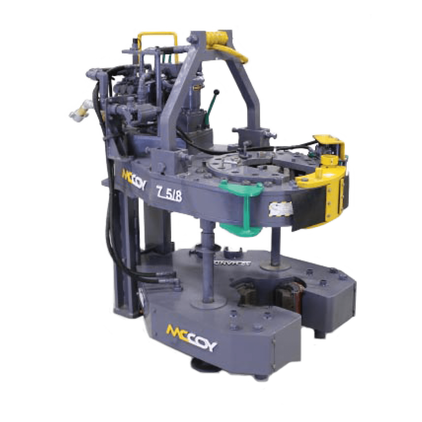
Casing tong handling tools (CTHTs) improve safety and efficiency by reducing the time to complete casing running operations. The CTHT automatically moves the casing tongs to and from well center, which decreases the personnel required to make up casing on the rig floor. Additionally, the CTHT increases the speed of running the casing tong to and from well center. Operations are faster and more consistent, from shift to shift, crew to crew.
The CTHT is an upgrade to an existing offshore drilling rig. This tool lifts and handles casing tongs, ranging in size from 7 5/8 in to 30 in, to and from the well center during casing running operations. And it can be used on any Cameron SmartRacker vertical pipe handling system or any other brand of column racker.
Oil Level Lube FittingsOPERATIONAL MAINTENANCENote 1. Note 2. Note 3. Note 4. Lube fittings should be greased weekly. Transmission should be checked after every trip, and if water or dirt is found in transmission, change oil. Under normal conditions oil should be changed every 100 work hours. Clean and grease Tong Head and Backup Tool after every trip, use kerosene or solvent and a wire brush for cleaning. After cleaning, apply cup grease to jaws, pins, ring gear and top seal. Hazards of steam cleaning Tong Head are: Water will be forced by top seal into transmission. also removing all lubricants from top seal and causing it to harden. If steam cleaning is used, Guide Bell should be bolted on place and after cleaning, the transmission should be checked for the presence of water.
SAFETY POINTS AND WARNINGSNote 5. Note 6. Note 7. Note 8. CAUTION, keep hands clear of Tong Head while Tongs are in operation. Caution should be taken while operating this equipment, as parts inside the Tong Head rotate. Do not crawl or stand under Tongs as hydraulic line could be cut or broken and Tongs will fall. Do not operate Power Tongs until the Anchor Arm is attached to the Tong and Anchor Post. Power should be off before any size equipment change, maintenance, or any other work is done to this equipment.DATESubsidiary of Galveston-Houston Company
A two-speed Hydra-Shift® motor coupled with a two-speed gear train provides (4) torque levels and (4) RPM speeds. Easily shift the hydraulic motor in low speed to high speed without stopping the tong or tublar rotation, saving rig time.
A patented door locking system (US Patent 6,279,426) for Eckel tongs that allows for latchless locking of the tong door. The tong door swings easily open and closed and locks when torque
is applied to the tong. When safety is important this locking mechanism combined with our safety door interlock provides unparalleled safety while speeding up the turn around time between connections. The Radial Door Lock is patented protected in the following countries: Canada, Germany, Norway, United Kingdom, and the United States.
The field proven Tri-Grip® Backup features a three head design that encompasses the tubular that applies an evenly distributed gripping force. The Tri-Grip®Backup provides exceptional gripping capabilities with either Eckel True Grit® dies or Pyramid Fine Tooth dies. The hydraulic backup is suspended at an adjustable level below the power tong by means of three hanger legs and allowing the backup to remain stationary while the power tong moves vertically to compensate for thread travel of the connection.

The present invention relates generally to making up and breaking out wellbore tubulars and, more particularly, to apparatus and methods for a simplified self-contained power tong for use in a rig floor environment.
Power tong systems maybe used to spin, makeup, or connect and breakout or disconnect wellbore tubulars that may have a wide range of diameters. Comparison studies between use of traditional separate tongs and spinners as compared with a self-contained power tong system makeup and breakout tool working under similar conditions have shown cost savings that range from one-quarter of a million to more than a million dollars per well, depending on the well conditions.
Separate, manually operated tongs, spinners, and/or chains are significantly slower and less accurate and consistent in making up and breaking out wellbore tubulars than a single tool or unit that does all such functions. Besides increased speeds of making up and breaking out tubular connections, other time saving advantages of a self-contained power tong unit also include factors such as eliminating the need to redress tongs when changing from drill pipe to drill collars and the integration of spinning with makeup and breakout functions. Due to the high daily cost of drilling rigs, comparison studies show that the time/cost savings can be substantial.
The self-contained power tong system also operates more reliably than separate tongs and spinners and may provide a central torque regulator that connects to and controls all components to assure consistent makeup. This feature prevents thread damage caused by over-tightening and automatically prevents errors that could result in under-torqued connections. Obviously, a single error, when making up hundreds of threaded connections in a drill string, can result in huge costs of time and material, and even loss of a well.
The self-contained power tong system also eliminates accident conditions commonly associated with separately moveable independent tongs which apply high torque and which are located by personnel on the floor. As well, independent tongs have attendant separate cables used to pull on each separate tong, and may also use snatch blocks. Thus, the personnel must work between high tension cables that pull on the tongs and accidents can easily occur under such conditions, e.g., if a tong loses its grip and moves rapidly across the rig floor accelerated by the high tension on the cable. Of course, accidents can slow work progress and significantly increase the costs of drilling.
Safety is also improved because the invention provides a single tool to perform all such functions, rather than separate elements, permits the use of central safety features such as, for instance, a lockout to prevent spinner operation if the tongs are not engaged, a safe location for the operator to stand and work, a design whereby the operator"s hands and feet are safely away from moving parts, elimination of spinning chains, and a lockout to prevent operation of the lift cylinder when any tong is engaged.
Because of the great utility of prior art self-contained power tong units to makeup and breakout pipes, and the increasingly expanding market for such devices, it has been found highly desirable to make further improvements. It would be highly desirable to simplify the operation of such devices thereby reducing the number of components necessary for operation of the power tong unit. Consequently, there remains a need for an improved self-contained makeup and breakout unit that reduces the complexity and therefore the costs such as manufacturing costs and maintenance thereof. Those skilled in the art have long sought and will appreciate the present invention which addresses these and other problems.
The present invention was designed to provide more efficient operation to thereby reduce drilling costs, to improve reliability of making and breaking pipe joints, to permit increased automation to reduce required manpower, to improve safety, and to free other rig equipment for other uses.
Accordingly, the invention comprises, in one embodiment thereof, a power tong system operable for making and breaking joints between wellbore tubulars. The power tong system may comprise one or more elements such as, for instance, a frame, a spinner secured to the frame that is operable for spinning the wellbore tubulars for the making and breaking of the joints, and/or a first member pivotally connected with respect to the frame such that the first member is rotatable with respect to the frame. The first member preferably defines a bore and/or a slot therein for receiving the wellbore tubulars. Other elements may, for instance, comprise a first plurality of gripping members mounted to the first member which are movable inwardly and outwardly for gripping and releasing the wellbore tubulars, and/or a piston/cylinder assembly comprising a piston slidable within a cylinder. The piston/cylinder assembly may be pivotally mounted with respect to the frame and with respect to the first member such that the first member is rotatable with respect to the frame in response to movement of the piston with respect to the cylinder. Additional elements may comprise a second member mounted to the frame also defining a slot therein for receiving the wellbore tubulars and a second plurality of gripping members mounted to the second member. The second plurality of gripping members may also be movable inwardly and outwardly for gripping and releasing the wellbore tubulars.
The power tong system may further comprise a control arm mounted to the first member, the control arm may be moveable between a first position and a second position, the first member may be rotatable for tightening the wellbore joints in the first position, the first member may be rotatable for loosening the wellbore joints in the second position. Other elements may comprise a fastener for selectively securing the control arm in the first position or the second position. In one embodiment, the fastener further comprises a pin, latch, or other fastening means.
The power tong system may further comprise a pivotal connection between the control arm and the first member and/or a pivotal connection between the control arm and the piston/cylinder assembly.
A method for a power tong system for making and breaking joints between wellbore tubulars are provided that may comprise one or more steps such as, for instance, mounting a plurality of gripping members to a rotatable member, providing that the gripping members are moveable inwardly toward the tubulars for gripping the wellbore tubulars and moveable outwardly away from the tubulars for releasing the wellbore tubulars, pivotally mounting a control to the rotatable member, connecting a piston/cylinder assembly which may comprise a piston and a cylinder, to the control arm such that the rotatable member rotates in response to movement of the piston with respect to the cylinder, providing that the control arm is moveable between a first position and a second position, providing that when the control arm is in the first position, then the member is operable for applying torque to the wellbore tubulars for making the joints, and/or providing that when the control arm is in the second position, then the member is operable for applying torque to the wellbore tubulars for breaking the joints.
In yet another embodiment, the power tong system may comprise, a frame, a first member pivotally connected with respect to the frame such that the first member is rotatable with respect to the frame, a first gripping assembly mounted to the first member for gripping and releasing the wellbore tubulars, a second member mounted to the frame, a second gripping assembly mounted to the second member for gripping and releasing the wellbore tubulars, lift members attached to the frame for moving the first member and the second member upwardly and downwardly to align the first member and the second member with respect to the joints, a joint connection detector operable for detecting joint connector components for producing a joint signal to indicate the joint connection components wherein the joint connection detector may be in a clearance position with respect to the joint connection components, and an automatic control for receiving the joint connector. The automatic control may be operable for operating the lift members to automatically align the first gripping assembly and the second gripping assembly with respect to the joints.
FIG. 1 is an elevational view, partially in phantom lines, showing a tong in a first position and selectively rotatable in a first direction in accord with one embodiment of the invention;
FIG. 2 is an elevational view, partially in phantom lines, showing the tong of FIG. 1 in a second position after rotation in the first direction in accord with one embodiment of the invention;
FIG. 3 is an elevational view, partially in phantom lines, showing the tong of FIG. 1 in a first position and selectively rotatable in a second direction in accord with one embodiment of the invention;
FIG. 4 is an elevational view, partially in phantom lines, showing the tong of FIG. 3 in a second position after rotation is the second direction in accord with one embodiment of the invention;
Referring now to the drawings and more particularly to FIG. 1, there is shown a preferred embodiment of rotatable tong 12 for applying torque to tubular connections. In FIG. 5 there is shown one possible embodiment of self-contained power tong system 10 in accord with the present invention utilizing one or more rotatable tongs 12 for applying torque to tubular connections.
Rotatable tong 12 may be utilized as an upper tong or a lower tong and may also be used for both an upper tong and a lower tong which operate in conjunction with each other by rotating in opposite directions. In the embodiment shown in FIG. 5, upper rotatable tong 12 operates in conjunction with a lower fixed position lower tong 14. Thus, upper tong 12 rotates and applies torque to upper pipe 16 while lower tong 14 acts as a back-up tong for holding lower pipe 18 in a fixed position. While in a preferred embodiment, lower tong 14 does not rotate, lower tong 14 could also be designed to rotate in an opposite direction with respect to upper tong 12, thereby doubling the degree of potential rotation available per operation for application of torque to joint 20. Upper tong 12 and lower tong 14 effectively provide sturdy upper and lower members which also support gripping members, as discussed below, in a suitable manner for applying high forces to the joint connections.
In a preferred embodiment, spinner 22 is utilized to quickly spin or rotate upper pipe 16 with respect to lower pipe 18 which is held in position by lower tong 14 until the joint is almost made up. Spinners are well known in the prior art and spinner 22 may utilize a known spinner design, if desired. While spinner 22 is capable of spinning pipe quickly until the threaded connection is almost made up thereby reducing the time required per joint, spinner 22 typically does not have sufficient power to apply the necessary torque required to complete the make-up for most tubular joints. Therefore, it is desirable to utilize spinner 22 in conjunction with a tong set capable of applying the necessary torque, as might be required per pipe manufacturer"s recommendations.
While upper tong 12 rotates only a relatively few degrees, as suggested in the different positions of upper tong 12 between FIG. 1 and FIG. 2, the upper tong 12 rotates with ample high-torque to complete the joint make-up according to the drill pipe manufacturers" specifications or any other standards.
FIG. 1, FIG. 2, FIG. 3, and FIG. 4 show, in some detail, the salient characteristics an embodiment of rotatable tong 12 of the present invention during various stages of operation, including rotation effectively in two different directions to thereby permit the same tong set to be utilized for both making-up and breaking-out pipe joint connections. Depending on the location of pin 24 in hole 26 or in hole 28, rotatable tong 12 may be made to effectively rotate in opposite directions for selectively tightening (making-up) or loosening (breaking-out) tubular joints, as discussed in more detail hereinafter.
In FIG. 1, rotatable tong 12 may comprise a circular member 30 with a circular outer perimeter 32. However, rotatable tong 12 may also be shaped differently around its perimeter. In any case, member 30 is built to have sufficient structural integrity to apply the necessary torque. Rotatable member 30 may comprise layers, support beams, housings to cover the elements shown in the drawings, and the like as desired, to provide the necessary structural integrity to apply the necessary torque.
Member 30 of rotatable tong 12 maybe mounted for rotation around rotation center point 34. Member 30 may be supported by suitable bearings as indicated at 37 in FIG. 5 between preferably telescoping and/or preferably moveable structural support members 38. Alternatively or in addition, suitable bearings may be provided for mounting to tong frame 36 (not shown). The bearings for mounting member 30, such as bearings 37 and/or other bearings, must be sufficiently strong to support the various forces acting thereof while torque is applied while constraining member 30 to rotate about center point 34.
In a preferred embodiment, rotatable tong 12 rotates in response to force produced by piston/cylinder assembly 40. Piston/cylinder assembly 40 actuates reciprocal movement of piston rod 42 with respect to cylinder housing 44. Piston/cylinder assembly 40 may be hydraulically or pneumatically actuated, as desired.
FIG. 1 shows rotatable tong 12 in the starting position prior to rotation with piston rod 42 extended with respect to cylinder housing 44. In the starting position slot or throat 62 is oriented to permit the pipe to move into or out of power tong system 10 prior to or subsequent to performing an operation involving applying torque to the pipe joint. FIG. 2 shows rotatable tong 12 in an ending position just after the joint has been operated upon with piston rod 42 retracted with respect to cylinder housing 44. The ending position may typically be in the range of thirty to one hundred degrees of rotation from the starting position. Movement arrows 46 and 48 in FIG. 1 show that rotational movement in the direction indicated by arrow 48 is associated with extension movement of piston rod 42 with respect to cylinder housing 44 as indicated by directional movement arrow 46. In this top view, extension of piston rod 42 results in counterclockwise rotational direction of member 30.
FIG. 3 and FIG. 4, as compared to FIG. 1 and FIG. 2, show the effect of removing pin 24 from hole 26 of member 30, pivoting control arm 58 until mating hole 60 in control arm 58 is aligned to hole 28, and inserting pin 24 therein. Pin 24 may be held in place by clips, latches, cotter pins, and so forth. With pin 24 mounted through hole 28 of member 30 and hole 60 of control arm 58, rotatable tong 12 may be made to effectively turn in the opposite direction from the starting position as shown in FIG. 1 and FIG. 2. In this case, as shown in FIG. 3, piston rod 42 is in a retracted position with respect to piston/cylinder assembly 40 when slot 62 is in the starting position. Piston rod 42 moves in the direction indicated by arrow 43, then member 30 rotates as indicated at 45, and piston/cylinder assembly rotates as indicated at 47.
Then as shown in FIG. 4, member 30 rotates counterclockwise from the starting position as indicated by arrow 64 as piston rod 42 extends in the direction of arrow 66 with respect to piston/cylinder assembly 40. Piston/cylinder housing rotates counterclockwise as indicated by arrow 68 and as discussed hereinbefore. To return to the opening position, piston rod 42 is contracted or moved as indicated by arrow 43 in FIG. 3 toward piston/cylinder housing 40. Corresponding to movement of piston rod 42 in the direction of arrow 43, member 30 of rotatable tong 12 rotates clockwise as indicated by arrow 45 and piston/cylinder housing 40 also rotates clockwise as indicated by arrow 47.
In a preferred embodiment, as best shown by numbers noted in FIG. 3, three gripping assemblies 80, 82, and 84 are utilized to grip the pipe within upper rotatable tong 12 and/or lower fixed position tong 14. The gripping assemblies of both upper tong 12 and lower tong 14 may be substantially similar, if desired. Gripping assemblies 80-84 may be substantially similar, and may operate similarly, if desired. Alternatively, one or more of the gripping assemblies may be substantially different and operate differently, if desired. Gripping assemblies 80-84 may be manually operated, hydraulically operated, or pneumatically operated, or some combination thereof. In a preferred embodiment, gripping assembly 82 is utilized as a guide member and may preferably be affixable in a desired selectable position that is determined by the size of pipe to be operated upon by tong system 10. Once fixed in the desired position, bite die 86 of gripping assembly 82 does not move but is affixed in position to thereby act as a guide to position the pipe in the correct position when the pipe is inserted into opening 62. On the other hand, gripping assemblies 80 and 84 move respective bite dies 88 and 90 radially inwardly and outwardly to thereby grip the pipe and/or release the pipe, as required. Rod 100, which may or may not be piston activated, or threadably activated, may be moveable for moving bite die 86 to the desired position. Adjustment member 102 may be utilized to select and affix piston rod 100 in the desired position either manually or automatically. Adjustment member 102 may have latches, thread connections, or the like to thereby affix and securely hold bite die 86 in the desired selected position.
Referring to FIG. 5, various means maybe provided to move system 10 into position for operation such as a moveable member, boom, cables, wheels, rails and the like for which base 116 may be adapted. System 10 may be moved into position for each joint, or may simply remain in a single position while building in or removing the pipe string. Mounts 118 may be used to lift system 10 upwardly or downwardly as required to position upper tong 12 and lower tong 14 in the desired vertical position with respect to the pipe. The mounts maybe hydraulically or pneumatically moveable, such as with pistons, as desired. Mounts 38, which may also be hydraulically or pneumatically moveable, may also be expandable/contractible to control the spacing between upper tong 12 and lower tong 14.
Slips 117 may be utilized to grip pipe 18 to support the pipe string, as desired. Slips 117 may be automatic slips, if desired. In one embodiment, slips 117 may comprise sender/receiver sensor/actuator 119 for sending receiving commands and status information about the slips, e.g., slips open or slips closed. Thus item 119 may comprise one or more or all components operable to provide an electronic sender, or electronic receiver, or electronic sensor, or an actuator. Sender/receiver/sensor/actuator 119 may be wireless or cable connected. Various types of sensors maybe utilized. For instance, pipe inspection device 120 and/or 122 maybe utilized to magnetically and/or electromagnetically inspect the pipe for defects when running the pipe into the wellbore or removing it therefrom. If desired, the pipe inspection results may also be utilized to detect the position of joint 20 and/or the tops or bottom of pipe 16 and 18. Once the position is known, then the system may automatically adjust its position to the pipe. Thus, pipe inspection device may comprise an electric coil, acoustic signal sender, magnetic flux detector, or other means for detecting discontinuities. The same components may also be used for detecting joint components such as the pin or box end of the joint as well as joints that are made up. The pipe inspection device and/or collar locator are mounted in a clearance position with respect to the pipe and do not require contact with the pipe to operate. If desired, the collar locator, if used, may be a separate component and spaced apart from the pipe inspection device. Moreover, more than one pipe inspection device or collar locator could be used for more complete inspection and/or faster location of collars to thereby more quickly move upper tong 12 and lower tong 14 into position.
In another embodiment, suitably located cameras, such as cameras 124, 126, and/or 128, maybe utilized, along with suitable lighting, to provide the driller or system 10 operator, a clear view of the position of the pipe joint. Thus, in FIG. 6, the position of the pipe and/or the position of system 10 and/or upper tong 12 and/or lower tong 14 may be seen in monitor 132 and compared with reference lines 130 for exact positioning. The optical system may be manually operated by the drill utilizing monitor 132 and/or other displays and controlling the equipment, such as system 10 height controls and/or the pipe handling equipment such as the blocks, slips, and the like.
Alternatively, the shapes of pipe connections are easily recognizable with an optical recognition system, for example in FIG. 6, that may be controlled by controller or computer 134. Optical recognition may be faster and, for example in FIG. 6, more reliable for locating the relative position of upper tong 12 and lower tong 14 with respect to a particular part of the joint which can be quickly recognized, e.g., the top outline of the socket or bottom outline of the pin, or when the pipes are connected then the profile of the connected joint. Thus, the optical system may comprise an optical collar locator that may be used to adjust the relative heights of upper tong 12 and lower tong 14. Moreover, the system may be used for inspecting the wellbore tubulars when the wellbore tubulars are clean and dry, as maybe provided when the tubulars are run into the hole by washing the pipe and allowing the pipe to dry.
If desired, automatic positioning means such as magnetic or coil produced collar signals, which may also be produced by the casing inspection coils, may be used in conjunction, such as for rough location, and automatic or manual visual means, such as monitor 132, may be used in conjunction for positioning upper tong 12 and lower tong 14 correctly.
Antenna 136 maybe used to receive signals wirelessly from the various sensors discussed above and/or the cameras. Moreover, antenna 136 and control 134 may be electronically interconnected to tong system 10 to operate tongs 12 and 14, raise and lower tongs 12 and 14, move system 10 as necessary, and for other desired automatic controls. Moreover, automatic control 134 may be utilized for operating slips 117 and may be utilized to send/receive status information and commands wirelessly or through cables to sender/receiver 119.
Thus, in any one of the manners discussed herein or in any combination thereof, enhanced tong operation is achieved. It may be seen from the preceding description that a new and improved powered tong system 10 has been provided. Although very specific combination examples have been described and disclosed, the invention of the instant application is considered to comprise and is intended to comprise any equivalent structure.
The foregoing disclosure and description of the invention is therefore illustrative and explanatory of one or more presently preferred embodiments of the invention and variations thereof, and it will be appreciated by those skilled in the art that various changes in the design, organization, order of operation, means of operation, equipment structures and location, methodology, and use of mechanical equivalents, as well as in the details of the illustrated construction or combinations of features of the various elements, may be made without departing from the spirit of the invention. As well, the drawings are intended to describe the concepts of the invention so that the presently preferred embodiments of the invention will be plainly disclosed to one of skill in the art but are not intended to be manufacturing level drawings or renditions of final products and may include simplified conceptual views as desired for easier and quicker understanding or explanation of the invention. As well, the relative size and arrangement of the components may be greatly different from that shown and still operate well within the spirit of the invention as described hereinbefore and in the appended claims. It will be seen that various changes and alternatives maybe used that are contained within the spirit of the invention. Moreover, it will be understood that various directions such as “upper,” “lower,” “bottom,” “top,” “left,” “right,” “inwardly,” “outwardly,” and so forth are made only with respect to easier explanation in conjunction with the drawings and that the components may be oriented differently, for instance, during transportation and manufacturing as well as operation. Because many varying and different embodiments may be made within the scope of the inventive concept(s) herein taught, and because many modifications may be made in the embodiment herein detailed in accordance with the descriptive requirements of the law, it is to be understood that the details herein are to be interpreted as illustrative and not in a limiting sense.

Don"t make a too shallow decision based solely on the cost of investment. The following key factors should be taken into considertion when deciding whether to rent or own the casing tongs / power tongs.
Modern power tongs are very sophisticated high-end equipment. The remotely operated tongs can be specially designed for your rig. The tongs are easy to rig up, as long as you know what you are doing. The casing crews operating the tongs should be experts with long experience operating the tongs.
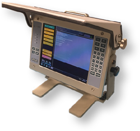
The power tongs comes with a computer based reading system. This is a delicate system capable of assisting the casing personnel in interpreting and approving the make-up. This reading requires trained and experienced personnel.
The power tongs are subject to heavy use and the maintenance demands a specialized workshop. Your supplier should be able to help you whenever the need, wherever you are. Spare parts or new tongs must be available within hours, and you need predictable routines for regular service on the tongs. This might be a costly, time-consuming effort if the rig owns the tongs.
Given today’s high level of specialization required to operate much of the equipment, it is hard to keep up with the rapid development on the technical side of oil and gas production. The benefits of renting the tools means less need for expensive training of crews, less logistical challenges in keeping gear functioning and available and a limited liability that makes you able to focus on the primary target: Getting to TD on time.
Find parts you need to repair or maintain your machines. At Alibaba.com, you can shop for hydraulic tubing power tong at affordable rates to tackle new obstacles and challenges. In the ever-changing industry, you can find what you need and speak to the supplier directly. Thanks to Alibaba’s collection of wholesale hydraulic tubing power tong you also get to buy these parts at lower prices, which means you can explore new levels every day more comfortably. From bulldozers to dragline excavators, wheel tractor scrapers to shotcrete machines, any part you need for a heavy-duty mining machinery; you can fi


 8613371530291