
power tong frame manufacturer
Our experienced and skilled power tong technicians play a major role in the safety and efficiency of a casing run. This makes the selection of your power tong service company a key component of overall performance.
ProTorque attracts and employs some of the industry’s most talented and experienced casing running technicians. Every detail of a casing run must be considered when looking for cost savings and efficiency; particularly on long production strings where every second counts while maintaining a safe operation. When making-up hundreds of connections, filling on the fly and selecting the correct handling equipment (air or hydraulic powered slips); we save time and effort on long challenging casing runs. ProTorque can meet handling requirements of up to 500 tons of hoist capability.

Eckel offers a broad range of accessories to compliment our power tongs. From torque control systems and gauges to case handles and tong straps, Eckel has the right accessory option for your specific application.
Eckel offers torque control systems to monitor the torque turn values when making up tubular connections with the system automatically stopping tong operation once reaching a specific torque. Any flaws in the make-up process will be readily shown in a graph.
The Door Interlock is offered as an optional safety feature for use with the power tong to prevent accidental operation of the power tong when the door is open. The door interlock prevents tong operation whenever the tong door is open by impeding hydraulic fluid to the tong motor.
A hydraulic Tri-Grip® or Cam Backup tool is optionally supplied with Eckel tongs. In operation this tool provides a backup when in break-out or make-up situations. This hydraulically operated backup tool, uses hydraulic cylinders and a head arrangement to insure slip-free operation.
A standard feature on many of our tongs. Dies have evolved since tongs became commonplace in the oilfields. Eckel has been at the forefront of this developing technology with the development of larger wrap-around type dies for many of its tong models. We offer coarse tooth design for normal carbon steel pipe and collars and fine tooth for special alloys such as 9, 13, 23, 25 chrome and fiberglass to greatly minimize markings on the tubulars.
Designed for improved safety when handling the tong. Up to four Case Handles can be optionally mounted on most tong models. Large top and bottom caps help protect the operator when maneuvering the tong on and off the tubulars.
Eckel continues to set industry safety standards with the optional Finger Guard Option. This shield covers the gap between the tong door and tong body, without limiting door operation. Door will open and close freely.
Industrial strength straps feature a rubber gripping surface to allow for easily pulling the tong on and off the tubular. These optional straps are mounted on the tong door and on both sides of the solid hanger area of the tong using a Lark"s Head Knot.
The adjustable motor port relief valve is used to control or limit the hydraulic pressure to the tong motor thus controlling the maximum torque output of the power tong. The valve controls only the hydraulic pressure to the tong motor leaving full system pressure available for other functions such as lift cylinder and hydraulic backup.
RPM Control: The RPM Control is a flow divider that decreases the amount of hydraulic fluid that reaches the tong, the remaining fluid is returned to the reservoir. By decreasing the amount of fluid reaching the tong the operator is able to control the maximum RPM"s the tong will deliver.
Tongs equipped with the optional Swivel Joints have improved hose life by absorbing system shock when pressured up and preventing twisting, kinking of the hydraulic hoses. In addition tongs are maneuvered more freely on the rig floor on and off the tubular.
The optional torque gauge assembly is used to measure the torque exerted in make-up or break-out operations. Consisting of a hydraulic cylinder and torque gauge connected together by a pressure hose, the torque gauge assembly senses and indicates the torque developed during an operation. For operation, the hydraulic cylinder is connected by a shackle to the rear of the tong; and a snub line is connected to the cylinder. The snub line is tied off to a solid part of the rig structure to form an angle of 90� in order for the gauge to indicate accurate torque readings.
This cylinder provides a means for raising and lowering the tong during operations and is recommended with tongs that have a hydraulic backup due to the extra weight of the tong. The lift cylinder maximum of travel varies depending on tong size.
The optional spring hanger is designed to permit the tong to move up or down to allow for thread length in make-up and break-out operations. When used, the spring hanger should be attached directly to the tong bridle ring and used as a hanger for the tong.
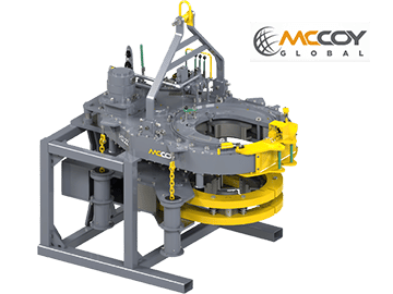
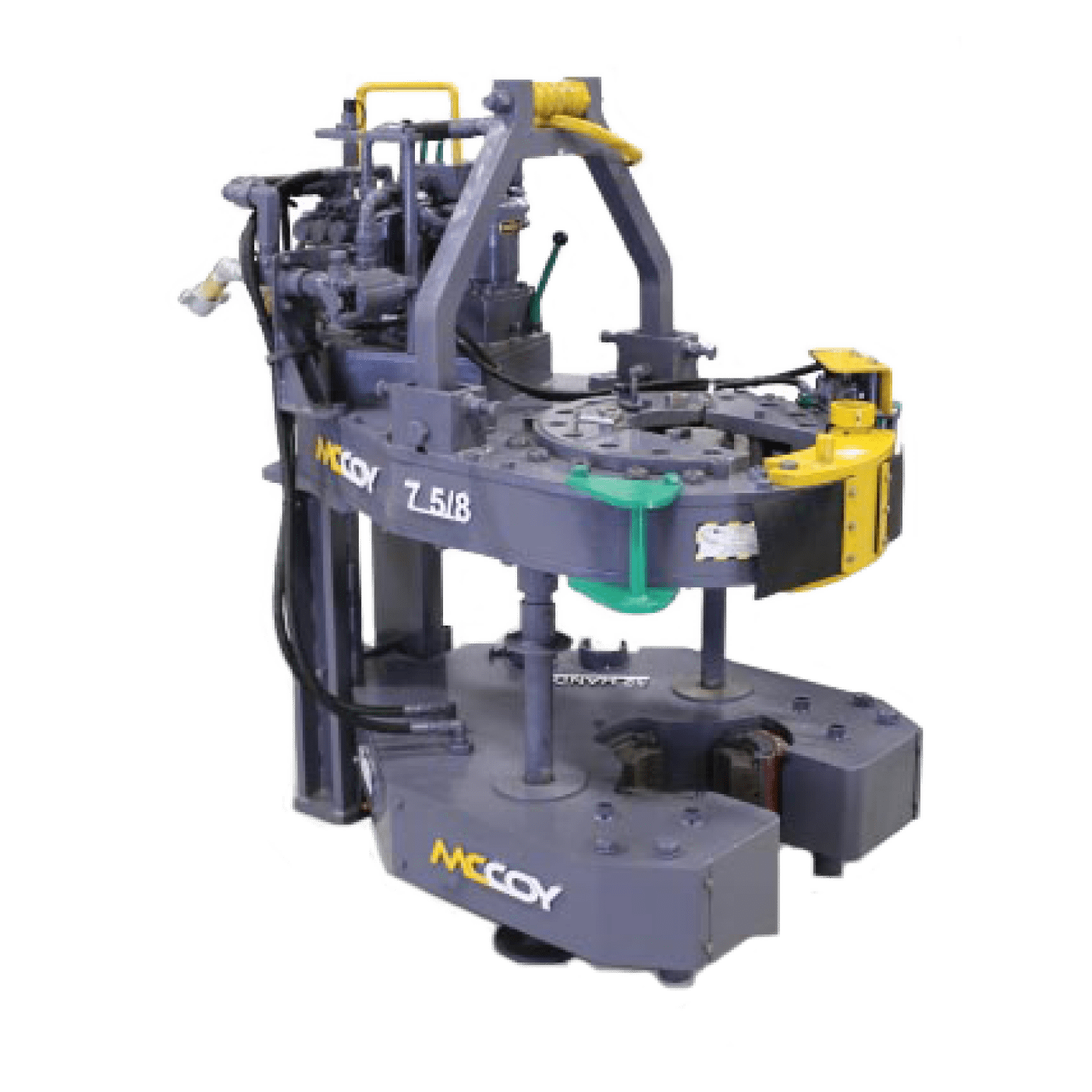
The HD26000 casing tong can handle tubulars as small as 10-3/4″ and as large as 26″ in diameter. Other sizes can be special-ordered. Tong can be mounted on either a CLINCHER® or a FARR® hydraulic backup. Available with McCoy’s patented WinCatt® data acquisition and torque control system for the make-up of tubular connections.
The present invention relates to open-head power tongs used in drilling operations, and more particularly, is directed to an improved means of actuating and deactuating the operation of the power tong drive means in response to the opened and closed positions of an access door.
As well known in the drilling industry, power tongs are employed in making-up and breaking-out operations of casings, tubings, rods, pipes and the like. More particularly, power tongs are used to grip and rotate lengths of drill pipe or the like to connect or join several lengths of pipe together to thereby form a drill string in a make-up operation, and in the alternative, to grip and rotate a length of drill pipe to disconnect it from the drill string in a break-out operation.
One type of power tong commonly used today is the open-head tong, such as the one shown and described in U.S. Pat. No. 4,060,014. The open-head tong has a bifrucated frame defining a central opening and a side opening communicating with the central opening for the passing therethrough of a drill pipe or the like. Due to the extreme costs of drilling, open-head tongs have become very popular, in that, they can easily and readily be moved into and out of an operative position when they are needed in the making up and breaking out of drill strings.
In operation, the open-head power tong exerts large rotational torques on the drill pipes, usually the larger the tong, the larger the torque output. Due to these large torque outputs and the resulting forces generated therefrom, the open-head tongs have been provided with an access door that bridges the gap between the bifrucated ends of the tong. The primary purpose of such an access door is to strengthen the tong structure so as to prevent, during the operation of the tong, the bifrucated ends from separating or springing apart, which not only results in damage to the tong, but could also inflict injury to the operating personnel. The access door, in addition to providing structural rigidity to the tong, also provides the operator with safety in bodily protecting him from the rotating pipe gripping and engaging jaws.
Such access doors perform very satisfactorily in providing structural rigidity to the tong and do provide protection to the operators from the rotating components of the tong when the door is properly latched in position during the make-up and break-out operations; however, in an effort to save time, operators have been known to operate the tong with the access door open, and in some instances, the operators have even removed the access door from the tong. Such operator"s carelessness not only causes costly structural damage to the tong, but also results in personal injury to the operator.
In U.S. Pat. No. 2,705,614 there is shown an open-head power tong having an automatic hydraulically powered access door, operably interconnected to the hydraulic cylinders that actuate the jaw gripping mechanism, which must be closed before the jaws can be actuated so as to rotate a drill pipe. Such door interlock mechanism has been specifically designed for the type of tong disclosed and is not readily adaptable to other types of power tongs, such as the one shown in the above-mentioned U.S. Pat. No. 4,060,014. Further, the hydraulic circuitry that is involved with such a powered access door is not only complicated, having expensive components, but is also, costly to maintain and repair. Still further, such door interlock mechanism does not provide adequate safety to an operator, in that, although the operator is protected from the pipe gripping and engaging mechanism when the door is closed, he is also subjected to the risk of having the power operated door being automatically swung into him as it is being closed, thus, creating a potentially dangerous and unsafe condition under which the operator must work.
The present invention obviates the problems experienced with access doors and disadvantages associated with the prior art door-interlock mechanisms by providing, as one of its principle objects, an improved door-interlock mechanism for an open-head power tong that ensures the access door is in a closed position before the tong can be operated, thereby preventing possible structural damage to the tong from operating the tong with the door open, as well as, preventing personal injury to the operators by protecting them from the various rotating components of the tong.
Another object of the present invention is to provide a door-interlock mechanism for an open-head power tong that is simple in structure and adaptable to all types of open-head power tongs.
Accordingly, the present invention, sets forth in an open-head power tong having an access door mounted on the tong and moveable between opened and closed positions, an improved door-interlock mechanism that includes means for controlling the operation of the tong in response to the opened and closed position of the door. More particularly, the control means preferably includes a pneumatic contact valve interconnected with a pneumatically piloted diverter valve operably associated with the power means of the tong such that the power means is placed in either an operative or inoperative condition in response to respective closed and opened positions of the door. Specifically, the pneumatic contact valve is so positioned in the vicinity of the side opening that the door, in its closed position, engages the contact valve thereby actuating the diverter valve to permit operation of the power means, and when, the door is moved from its closed position out of engagement with the contact valve, the contact valve causes the diverter valve to deactuate the power means, thus stopping the operation thereof.
FIG. 1 is a top plan view of an open-head power tong incorporating the improved door-interlock mechanism of the present invention with the access door being in its closed position in engagement with the contact valve which actuates the diverter valve.
FIG. 2 is a diagrammatic fragmentary view of the power tong showing the side edge portion of the access door with the door latch removed and with the contact valve being in disengagement with the door which is partly open.
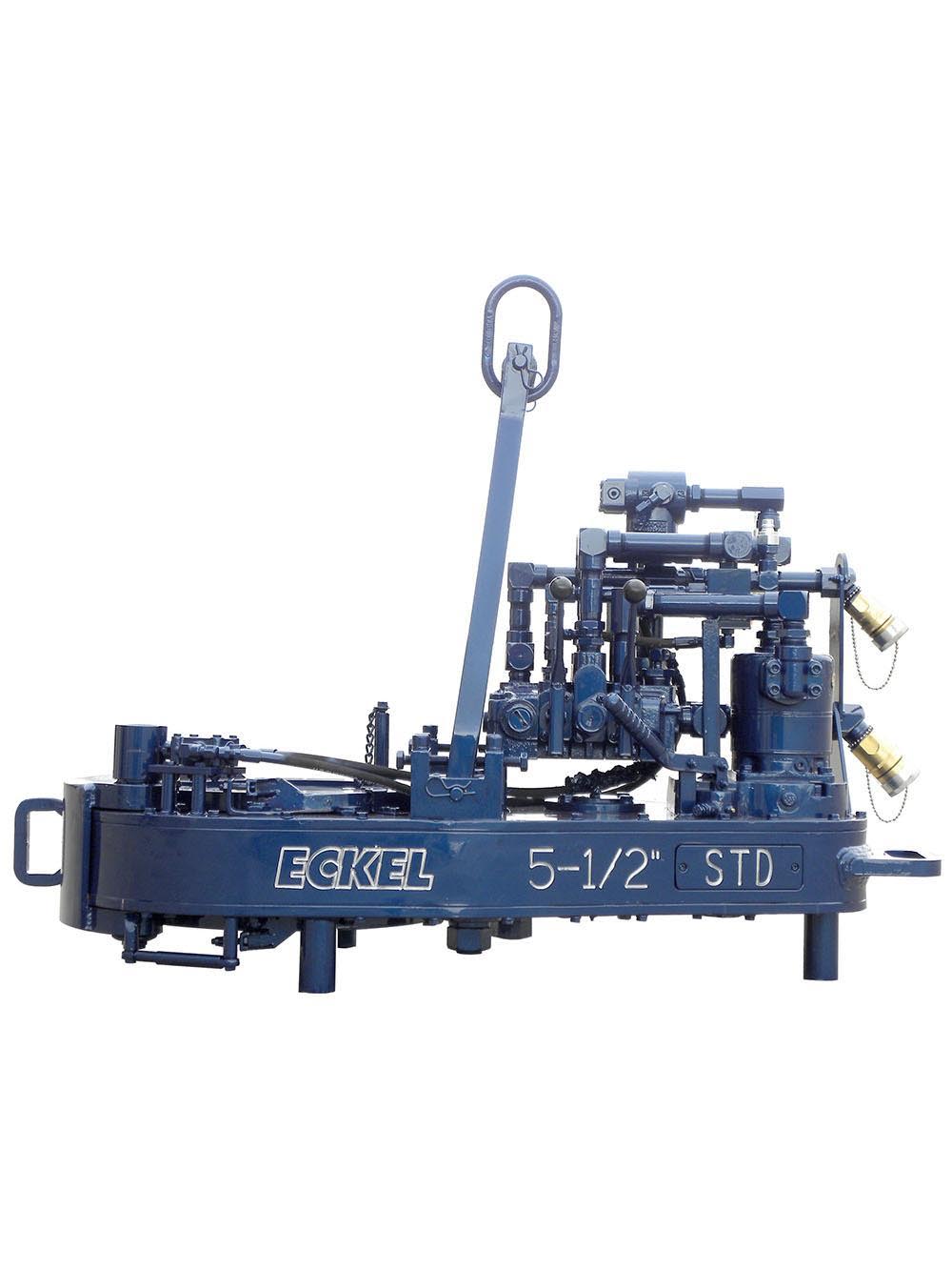
Referring to the drawings, and particularly, to FIG. 1, there is shown, for illustration purposes only, an open-head power tong, being generally indicated by the numeral 10, incorporating the principles of the present invention. The tong illustrated in FIG. 1 is of the type shown and described in U.S. Pat. No. 4,060,014, and thus, for the sake of brevity, since the tong itself forms no part of this invention, only a brief description of the tong will follow.
Briefly, as best seen in FIG. 1, the power tong 10 is comprised of a bifrucated frame structure 12 defining a central drill pipe receiving opening, and a side opening that communicates to the central opening for laterally passing a drill pipe therewithin. Rotatably supported within the frame structure 12 is a pipe engaging and gripping means that includes jaws 14 that swing into and out of the central opening for gripping and rotating a drill pipe disposed within the central opening during make-up and break-out operations of a drill string. The pipe engaging and gripping means with its associated jaws 14 are rotatably driven through a suitable drive train (not shown) by power means such as the hydraulic motor 16 which receives fluid under pressure from a suitable hydraulic pump (not shown) and through a hydraulic control valve 17. The valve 17 is conventional, being moveable between three spool positions; one position being such that the fluid drives the motor in a forward clockwise direction, another position being such that the hydraulic fluid drives the motor in a reverse counterclockwise direction, and the third position being a neutral position wherein fluid passes through the valve to the return line that returns the fluid to a reservoir (not shown) for recirculation thereof.
Also supported on the frame structure 12 is an access door 18, adapted to span or bridge the access opening defined between the bifrucated end portions so as to provide structural rigidity to the power tong 10, as well as, to protect the operator from the various moving components, such as the jaws 14. One end of the access door 18 is hinged to an end of one of the frame bifrucations by a pivot pin 20 whereas the free end of the door is provided with a self-latching arm 22 that engages a latch member 24 mounted on the other bifrucation so as to positively latch the door when it is closed. The door and the door latching mechanism are of the type shown and described in a pending U.S. application, bearing U.S. Ser. No. 791,752; filed Apr. 28, 1977; and entitled TONG LOCKING MECHANISM. The door and the latching mechanism forms no part of this invention and thus a further description will not be given.
To ensure that the tong 10 is only operated when the door 18 is closed, closing the access opening, the tong 10 is provided with an interlock mechanism which basically includes a contact valve 26, engageable by the door 18, and a hydraulic diverter valve 28, operably associated with the hydraulic motor 16 so as to permit flow of hydraulic fluid to the motor, or, in the alternative position, to bypass the flow of hydraulic fluid around the motor.
As seen in FIGS. 1 and 2, in particularly FIG. 2, the contact valve 26 is mounted on the front side of the frame structure 12, in proximity to the access opening, and is so positioned to be engaged by the door 18 when the door is closed and disengaged when the door is opened. The contact valve 26 has an internal spring that biases the valve to its disengaged position. A suitable source for generating pneumatic pressure, such as a compressor (not shown) is provided to supply pressure to the valve 26 through inlet line 30 and therethrough, when valve 26 is in its engaged position, via line 62 to one end of the pneumatic piloted hydraulic diverter valve 28. When pressure is so applied on the diverter valve 28, the valve is so positioned to permit hydraulic fluid to flow to the motor 16 and thereby its operation. However, when pressure is relieved from the diverter valve 28, which is caused when the door 18 is disengaged from the contact valve 26, an internal biasing spring forces the valve to a position which diverts the flow of hydraulic flow around the motor 16, and thus, stoppage thereof.
Now turning to FIG. 3 which schematically represents the various operating components as well as the hydraulic and pneumatic circuitry associated therewith, the operation of the door interlock will be further described. First, it should be noted that both the hydraulic source and the pneumatic source are fully operating with respective fluids being under pressure in inlet lines, the access door 18 being closed, engaged with the actuating arm of the contact valve 26, the piloted diverter valve 28 being detented so as to pass the flow of hydraulic fluid around the motor 16, and with the hydraulic spool control valve 17 being in its neutral position such that fluid passes directly therethrough to the reservoir tank via inlet line 34, passageway 36, return line 38. Thus, as the spool valve 17 is shifted to its forward drive position, hydraulic fluid passes from the inlet line 34, through passageway 40, to line 42, through passageway 44 (of diverter valve 28), to line 46 which directs fluid into the left-hand side of the motor 16, and then via lines 48,49 to passageway 50 of valve 18 which is internally connected to the hydraulic return line 38. If the spool valve 17 is shifted in an opposite direction so as to reverse the direction of the motor 16, fluid flows via line 34, through passageway 52 to line 49 and line 48 to the right side of the motor 16, and then returns via lines 46, passageway 44, line 42 to passageway 54 which is internally connected to return line 38. It can be thus seen that when pressure is applied on the diverter valve 28, it is so positioned to pass hydraulic fluid either to one or the other sides of the motor 16 to thereby drive the rotating components of the tong 10 in either forward or reverse directions depending on the forward or reverse positions of the control valve 17. However, when the pneumatic pressure is relieved from the diverter valve 28, the internal spring forces the valve to the right, thus changing the flow path of the hydraulic fluid so as to bypass the motor 16. In such pressure relief position of the diverter valve 28, the fluid flow path is via lines 49,58, passageway 56 and line 42, thereby bypassing the flow of fluid to the motor 16. Since the flow of fluid through line 46 is blocked, no fluid passes to the motor 16, thus rendering it inoperative.
It can be understood from the foregoing that the described interlock-mechanism controls the operation of the hydraulic motor 16, and thus the operation of the tong 10, in response to the open and closed positions of the access door 18, such that the tong 10 can only be operated with the access door 18 in its closed position, and thereby eliminating the possibility of structural damage to the tong from operating same with the door open, as well as, providing safety to the operator from exposure to the various operating components of the tong.
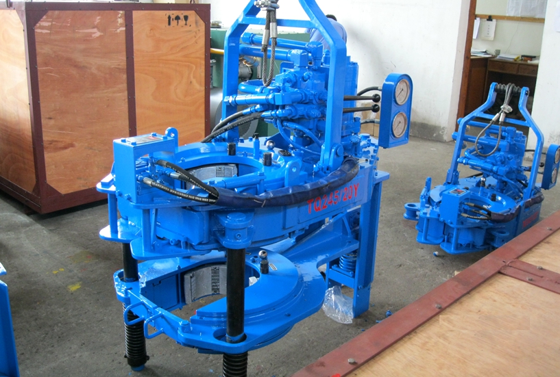
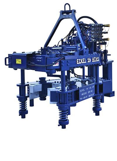
XQ140 micro-marking and no-marking hydraulic power tongs is a special equipment and open power tongs which is applicable to make up or break out 41/2"-51/2" casing during oil field work over operation. Master and back tong device adopts jaw plate type multi-point clamping mechanism.Can choose contour coated rig dies or pyramid tooth , to ensure the column minimum damage, and can improve the pipe thread connection quality, reduce due to improper work over pipe accident etc..
1. The tongs head is the open structure which is quick and convenient for entering and retreating working position. The integral tong head has good hardness and rigidity.
2. Master tong is roller climbing two jaw plate structure,can install arc tooth die ,the contact surface is more larger and clamp no deformation, The assembly and disassembly is very convenient. The optimum tangent-diameter ratio design ensures reliable clamping and easy slope retreating.The back tong is the three-jaw-plate structure pushed by hydraulic cylinder. The structure is simple and the clamping is reliable; The minimum damage to the tubular column can be ensured, and the main body of the pipe string can be clamped.
6. Master and back tong adopt integral frame structure,back tong is floating connection,The master and back tong adjustable distance, reduce the damage of pipe string shackle;
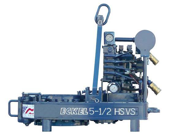
Model XQ28/2.6 hydraulic power tong is an improved type of XYQ1.8 which is used to make up and break out sucker rod thread in Well Service. This product has the following features:
A. The structure is compact, concise and light. Master tong is driven by a low-speed large torque hydraulic motor that matches with a manual control valve. The backup tong is just like a spanner. The total weight is approximately equal to XYQ1.8.
B. The operating is briefness and convenience with high efficiency. Put the respondence size jaw set into master tong and the respondence size glutting into backup tong, turning the reset knob incorrect direction then can make up and break out sucker rod by operating manual control valve. Two speed, snapping at low speed, spinning at high speed.

The present invention relates generally to tools used in oilfield operations and more particularly to a backup tong suitable for use in dual tubing strings operations in conjunction with a power tong to make up or break apart joints of pipe strings.
Tongs have long been used in oilfield operations to grip and rotate pipe segments and thereby "make up" or "break apart" joints in a pipe string. A backup tong is used to grip and prevent rotation of the lower pipe in the joint while the upper pipe segment is gripped and rotated by a second tong. Typically, this second tong is not manually used to rotate the upper pipe, but is instead power-driven. Backup tongs are thus used only in conjunction with a second tong, whether the second tong be manually operated or actually "powered."
Tongs are generally designed to operate only on a single string of pipe. In other words, they are designed to grip and/or rotate a single pipe without regard to whether there may be any other pipes nearby, much less within the same wellbore. In a situation in which there are two pipe strings in the same casing, the tongs may be used if the strings are sufficiently far apart to allow access to each string or the two strings may be "splayed" apart to make room to engage the tongs. Even if the tongs can be used with dual tubing strings (with or without splaying the pipe strings), the tongs must be used on the first (the nearest) of the two pipe strings, then backed off, moved to the opposite side of the pipe strings and then moved onto the second pipe string, which after moving the tongs becomes the nearer of the two. The movement of the tongs back and forth from one side of the tubing strings to the other takes a great deal of time and creates a much greater risk of harm to the tong operator than when the tongs are simply moved forward or backward onto or off of a single pipe string. The use of prior art tongs (which are designed for use in single string operations) is therefore troublesome and time consuming in situations where there are two or even three pipe strings.
Although this disclosure relates to backup tongs, the scope of the problem is also apparent from the shortcomings of prior art power tongs. U.S. Pat. No. 4,590,823 to Neves, et al. shows an open-throat power tong which allows one pipe string to be gripped while the adjacent string is positioned within the outer throat of the tong (i.e., the opening between the gripping mechanism of the tong and the exterior of the tong). While Neves, et al. discloses a type of power tong which can be used with dual pipe strings, it does not disclose any way to overcome the problem of having to move the power tong, or a backup tong used therewith, from side to side to properly position the first and second pipe strings between the jaws of the tong and in the throat of the tong, respectively.
Backup tongs, like power tongs, are typically designed for use in single string operations. As noted above, some designs of backup tongs may be used in dual string operations by utilizing an open throat design which can accommodate a second pipe in the outer throat of the tong while gripping a first pipe string between its jaws. While this method of using a backup tong is known in the art, it requires that the backup tong be used on a first string, then backed off of the first string, moved approximately 180 degrees to face the second pipe string and then moved forward to engage the second pipe string. Although this procedure makes dual string operations possible with backup tongs designed to operate on a single string, the extra movement is time consuming and inefficient and poses a much greater risk of injury than a tong which does not have to be repeatedly swung around the pipe strings.
The shortcomings of the devices in the prior art are overcome in the present invention by providing a backup tong which does not need to be backed off of a first pipe string, swung around to the opposite side of the string and engaged with a second pipe string from the opposite direction. This is accomplished by placing the gripping members of the backup tongs at the end of a set of extended jaw members which have an inner throat between the gripping members and the main body of the backup tong. This inner throat is directly adjacent to the pipe which is gripped by the jaws of the backup tong and is on the side of the pipe opposite the outer throat, through which the pipe passes as the tong is moved onto the pipe. This allows the invention to grip the further of two strings while the nearer string is within the inner throat of the backup tong, then release the far string, move back and grip the near string. Likewise, in backout mode, the inventive tong can grip the nearer of two pipe strings as a conventional backup tong would, then simply release the first string and move forward to grip the second string while the first string is disposed in the inner throat of the backup tong. The inner throat of the tong can also be designed to accommodate three pipe strings, although three-string operations (one string in the jaws of the tong and two strings in the inner throat) are rarely conducted. Obviously, the invention has utility in single-string operations as well.
The ability to conduct dual string operations with minimal movement of the backup tong greatly reduces the time required to make or break the joints of dual pipe strings. This in turn provides increased efficiency, reduced costs and greater safety for persons operating the tongs.
It is therefore an object of the invention to provide a backup tong which can accommodate a second pipe on either side of a first pipe which is held between the jaws of the backup tong and thereby allows the tong to grip either pipe with only a small lateral movement.
It is another object of the invention to provide a backup tong which reduces the time, effort and related expense to make up and break apart pipe joints in multiple-string operations.
It is another object of the invention to provide a backup tong which reduces the risk of harm to the tong operator by minimizing the movement of the backup tong during its use in multiple-string operations.
Referring to FIG. 1, one embodiment of the backup tong of the present invention is shown. The body of the backup tong has an upper plate 11 and a lower plate 10. Between these plates are two jaw members 12, 13 which pivot about bolts 14, 15. At the outer ends of the jaw members 12, 13 are gripping members 16, 17. Gripping members 16, 17 carry dies 21, 22 which actually come into contact with and grip a pipe which is situated between them. A hydraulic actuator (not shown) is disposed between the jaw members and connected to these members at their inner ends (the ends opposite gripping members 16, 17). As the hydraulic actuator forces the non-gripping ends of the jaw members outward, the jaw members pivot around bolts 14, 15 and force gripping members 16, 17 inward. Likewise, when the actuator pulls jaw members 12, 13 inward, the pivoting of the jaw members forces gripping members 16, 17 outward.
Although this embodiment utilizes the two pivoting jaw members, this is considered a design choice and may be replaced in the invention by a wide variety of jaw designs which are known in the art. These jaw designs may incorporate pivoting jaw members, stationary jaw members with laterally movable gripping members, or any other arrangement of jaw members and/or gripping members which allows the incorporation of an inner throat into the tong design.
The backup tong assembly shown in FIG. 4, and particularly upper plate 11 and lower plate 10, is formed with an inner throat or recess 19 immediately behind gripping members 16, 17 (i.e. between gripping members 16, 17 and plates 10, 11). Because recess 19 is disposed between pivot bolts 14 and 15, jaw members 12, 13 essentially pivot around the recess so that a pipe string disposed within the recess is not disturbed by operation of the backup tong.
The preferred embodiment of the invention is used in conjunction with a power tong. In FIGS. 1 and 2, the invention is shown mounted to a torque post 30. The invention is mounted on the torque post by means of two pivoting arms 28, 29 which allow the invention to shift laterally with respect to a line extending from the center of recess 19 to a point midway between gripping members 16, 17. Also mounted on torque post 30 is a power tong 2 which is preferably capable of dual-string operations. The mounting of the backup tong 1 and the power tong 2 on the torque post prevents them from rotating with respect to each other.
In the preferred embodiment, the power tong 2 which is used with the inventive backup tong 1 is also capable of dual-string operations. FIG. 1 shows a closed-throat power tong which comprises a multi-sectioned gripping assembly 40 mounted on power tong body 41. Also mounted on power tong body 41 is drive motor 44. Contained within power tong body 41 is the drive mechanism (not shown) which transfers power from the drive motor 44 to the gripping assembly 40, causing the gripping assembly to rotate. The operation of the drive mechanism and the rotation of the gripping assembly are regulated by controls 45. The physical positioning of the backup tong and power tong are facilitated by structural arms 37, 38 which are rigidly connected to torque post 30 structural arms 37, 38 have handles 35, 36 which allow the tong operator to grasp and position the backup and power tongs.
The power tong body 41 is mounted to power tong frame 42. Power tong frame 42 is in turn connected to the upper portion of torque post 30. As mentioned above, the attachment of both power tong 2 and the inventive backup tong 1 to torque post 30 prevents the tongs from rotating relative to each other. The torque between these two components is therefore transferred to the pipe and coupling which are held by the power tong and backup tong, respectively.
Referring to FIGS. 1 and 3, it can be seen that the present invention can operate on dual pipe strings without having to move the backup tongs from one side of the dual pipe strings to the other, as is the case with prior art backup tongs. Both the invention, and conventional single-string backup tongs can be positioned to grip the closer of a pair of adjacent pipe strings in the same way (see FIGS. 2 and 4). In order for a conventional backup tong to grasp the second (the farther) of the pipe strings, the tong must be backed off the near string, moved to the opposite side of the pair of pipe strings so that the second string is the nearer of the two, and moved forward to engage the pipe string. In other words, the conventional tong can only engage the nearer of the two pipes, so it must be repositioned on the opposite side of the dual strings before it can engage the second pipe.
The invention, on the other hand, simply releases the first string, moves forward several inches so that the first pipe string is within the throat of the tong, and grips the second pipe string. The inventive tong can, of course, also initially grip the second pipe string while the first pipe string is within the inner throat of the tong, then release the second string, move backward and grip the first string. No time or effort is wasted in having to move the backup tong from one side of the pair of pipe strings to the other--the tong is simply shifted forward or backward several inches. (It does not matter which of the two pipes is gripped first or second by the tong.)
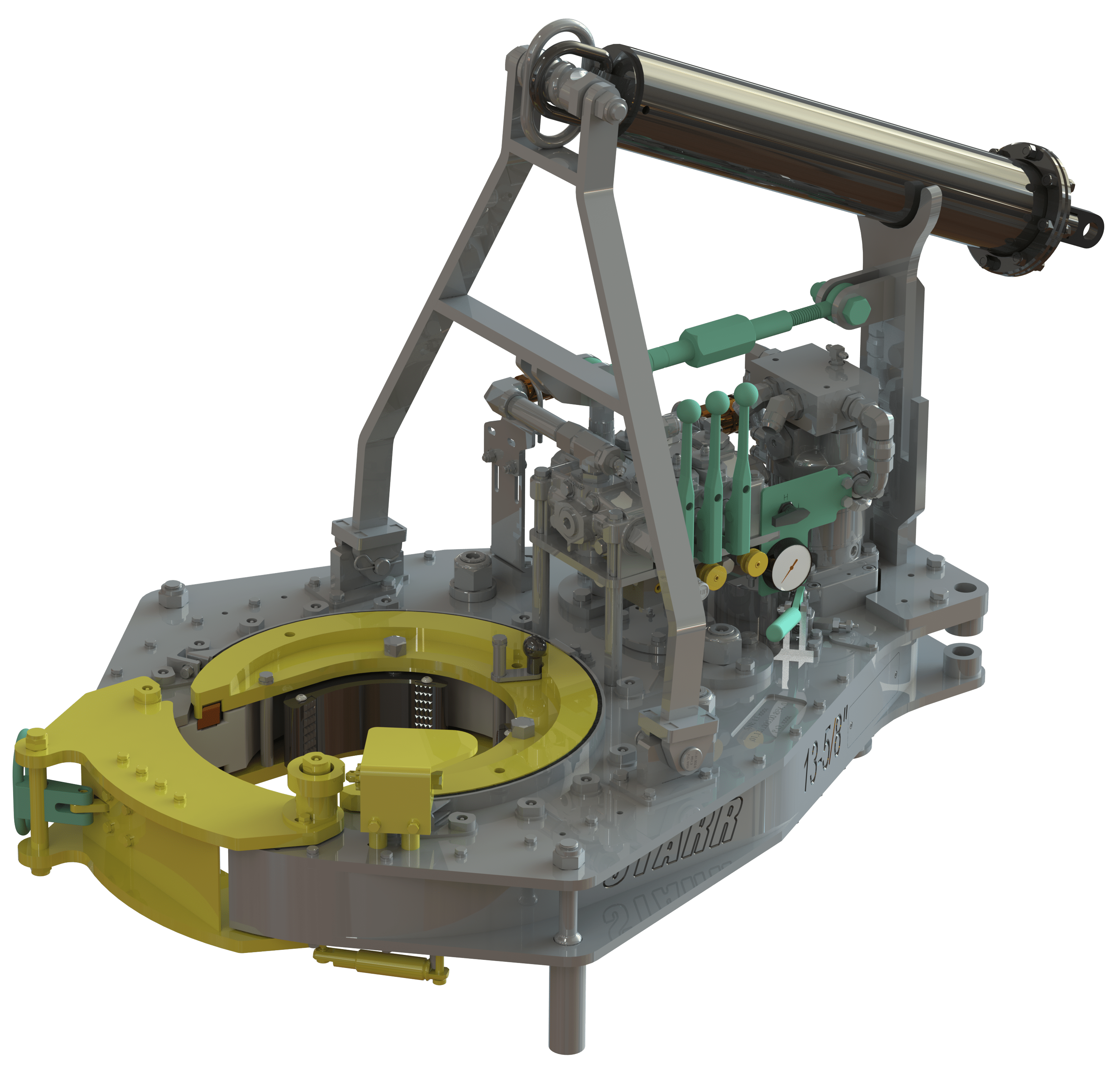
US Power Tong’s 13-5/8” Standard Model Casing Tong (Pics below) is capable of biting pipe sizes 4-1/2” in diameter up to 13-5/8” in diameter. With its’ high torque capability rated at 45,000 lb./ft. as well as its’ lightweight and compact design, it makes this tong one of the most versatile and convenient models US Power Tong offers. This tong also offers a door interlocking system which helps reduce the chances of accidents. This tong operates from a hydraulic power unit that provides power to the tong. The biting system this tong uses is that of a cam style biting system.
US Power Hydraulic Casing Tong 13-5/8″ Light Duty Model Rated @ 30,000 lb/ft. w/Safety Interlock Door and Solid Hanger. (USPT-1619) or Hydraulic Casing Tong Standard Duty Model Rated @ 45,000 lb/ft. w/Safety Interlock Door, Solid Hanger, and High Torque Door. (USPT-1190)
Accessories and added options are also available with US Power Tong’s 13-5/8” Standard Hydraulic Casing Tong. Options that are available are listed below and the paragraphs following describe each item:
The present invention relates generally to making up and breaking out wellbore tubulars and, more particularly, to apparatus and methods for a simplified self-contained power tong for use in a rig floor environment.
Power tong systems maybe used to spin, makeup, or connect and breakout or disconnect wellbore tubulars that may have a wide range of diameters. Comparison studies between use of traditional separate tongs and spinners as compared with a self-contained power tong system makeup and breakout tool working under similar conditions have shown cost savings that range from one-quarter of a million to more than a million dollars per well, depending on the well conditions.
Separate, manually operated tongs, spinners, and/or chains are significantly slower and less accurate and consistent in making up and breaking out wellbore tubulars than a single tool or unit that does all such functions. Besides increased speeds of making up and breaking out tubular connections, other time saving advantages of a self-contained power tong unit also include factors such as eliminating the need to redress tongs when changing from drill pipe to drill collars and the integration of spinning with makeup and breakout functions. Due to the high daily cost of drilling rigs, comparison studies show that the time/cost savings can be substantial.
The self-contained power tong system also operates more reliably than separate tongs and spinners and may provide a central torque regulator that connects to and controls all components to assure consistent makeup. This feature prevents thread damage caused by over-tightening and automatically prevents errors that could result in under-torqued connections. Obviously, a single error, when making up hundreds of threaded connections in a drill string, can result in huge costs of time and material, and even loss of a well.
The self-contained power tong system also eliminates accident conditions commonly associated with separately moveable independent tongs which apply high torque and which are located by personnel on the floor. As well, independent tongs have attendant separate cables used to pull on each separate tong, and may also use snatch blocks. Thus, the personnel must work between high tension cables that pull on the tongs and accidents can easily occur under such conditions, e.g., if a tong loses its grip and moves rapidly across the rig floor accelerated by the high tension on the cable. Of course, accidents can slow work progress and significantly increase the costs of drilling.
Safety is also improved because the invention provides a single tool to perform all such functions, rather than separate elements, permits the use of central safety features such as, for instance, a lockout to prevent spinner operation if the tongs are not engaged, a safe location for the operator to stand and work, a design whereby the operator"s hands and feet are safely away from moving parts, elimination of spinning chains, and a lockout to prevent operation of the lift cylinder when any tong is engaged.
Because of the great utility of prior art self-contained power tong units to makeup and breakout pipes, and the increasingly expanding market for such devices, it has been found highly desirable to make further improvements. It would be highly desirable to simplify the operation of such devices thereby reducing the number of components necessary for operation of the power tong unit. Consequently, there remains a need for an improved self-contained makeup and breakout unit that reduces the complexity and therefore the costs such as manufacturing costs and maintenance thereof. Those skilled in the art have long sought and will appreciate the present invention which addresses these and other problems.
The present invention was designed to provide more efficient operation to thereby reduce drilling costs, to improve reliability of making and breaking pipe joints, to permit increased automation to reduce required manpower, to improve safety, and to free other rig equipment for other uses.
Accordingly, the invention comprises, in one embodiment thereof, a power tong system operable for making and breaking joints between wellbore tubulars. The power tong system may comprise one or more elements such as, for instance, a frame, a spinner secured to the frame that is operable for spinning the wellbore tubulars for the making and breaking of the joints, and/or a first member pivotally connected with respect to the frame such that the first member is rotatable with respect to the frame. The first member preferably defines a bore and/or a slot therein for receiving the wellbore tubulars. Other elements may, for instance, comprise a first plurality of gripping members mounted to the first member which are movable inwardly and outwardly for gripping and releasing the wellbore tubulars, and/or a piston/cylinder assembly comprising a piston slidable within a cylinder. The piston/cylinder assembly may be pivotally mounted with respect to the frame and with respect to the first member such that the first member is rotatable with respect to the frame in response to movement of the piston with respect to the cylinder. Additional elements may comprise a second member mounted to the frame also defining a slot therein for receiving the wellbore tubulars and a second plurality of gripping members mounted to the second member. The second plurality of gripping members may also be movable inwardly and outwardly for gripping and releasing the wellbore tubulars.
The power tong system may further comprise a control arm mounted to the first member, the control arm may be moveable between a first position and a second position, the first member may be rotatable for tightening the wellbore joints in the first position, the first member may be rotatable for loosening the wellbore joints in the second position. Other elements may comprise a fastener for selectively securing the control arm in the first position or the second position. In one embodiment, the fastener further comprises a pin, latch, or other fastening means.
The power tong system may further comprise a pivotal connection between the control arm and the first member and/or a pivotal connection between the control arm and the piston/cylinder assembly.
A method for a power tong system for making and breaking joints between wellbore tubulars are provided that may comprise one or more steps such as, for instance, mounting a plurality of gripping members to a rotatable member, providing that the gripping members are moveable inwardly toward the tubulars for gripping the wellbore tubulars and moveable outwardly away from the tubulars for releasing the wellbore tubulars, pivotally mounting a control to the rotatable member, connecting a piston/cylinder assembly which may comprise a piston and a cylinder, to the control arm such that the rotatable member rotates in response to movement of the piston with respect to the cylinder, providing that the control arm is moveable between a first position and a second position, providing that when the control arm is in the first position, then the member is operable for applying torque to the wellbore tubulars for making the joints, and/or providing that when the control arm is in the second position, then the member is operable for applying torque to the wellbore tubulars for breaking the joints.
The method may further comprise providing a frame, and pivotally mounting the rotatable member to the frame. The method may further comprise mounting a tubing inspection tool to the frame. The method may further comprise utilizing the tubing inspection tool for locating the joints with respect to the rotatable member.
In yet another embodiment, the power tong system may comprise, a frame, a first member pivotally connected with respect to the frame such that the first member is rotatable with respect to the frame, a first gripping assembly mounted to the first member for gripping and releasing the wellbore tubulars, a second member mounted to the frame, a second gripping assembly mounted to the second member for gripping and releasing the wellbore tubulars, lift members attached to the frame for moving the first member and the second member upwardly and downwardly to align the first member and the second member with respect to the joints, a joint connection detector operable for detecting joint connector components for producing a joint signal to indicate the joint connection components wherein the joint connection detector may be in a clearance position with respect to the joint connection components, and an automatic control for receiving the joint connector. The automatic control may be operable for operating the lift members to automatically align the first gripping assembly and the second gripping assembly with respect to the joints.
The system may further comprise automatic slips and a sender for the automatic slips that is used to send status information which may be received by the control. A plurality of sensors may be provided which are operable for measuring pressure, movement, and the like, and may be used, for instance, for determining torque versus turn during the making up of the joints. Other elements may comprise a piston/cylinder assembly which includes a piston slidable within a cylinder wherein the piston/cylinder assembly may be pivotally mounted with respect to the frame and/or a control arm mounted to first member. The piston/cylinder assembly may be pivotally connected to the control arm such that the first member is rotatable with respect to the frame in response to movement of the piston with respect to the cylinder.
FIG. 1 is an elevational view, partially in phantom lines, showing a tong in a first position and selectively rotatable in a first direction in accord with one embodiment of the invention;
FIG. 2 is an elevational view, partially in phantom lines, showing the tong of FIG. 1 in a second position after rotation in the first direction in accord with one embodiment of the invention;
FIG. 3 is an elevational view, partially in phantom lines, showing the tong of FIG. 1 in a first position and selectively rotatable in a second direction in accord with one embodiment of the invention;
FIG. 4 is an elevational view, partially in phantom lines, showing the tong of FIG. 3 in a second position after rotation is the second direction in accord with one embodiment of the invention;
Referring now to the drawings and more particularly to FIG. 1, there is shown a preferred embodiment of rotatable tong 12 for applying torque to tubular connections. In FIG. 5 there is shown one possible embodiment of self-contained power tong system 10 in accord with the present invention utilizing one or more rotatable tongs 12 for applying torque to tubular connections.
Rotatable tong 12 may be utilized as an upper tong or a lower tong and may also be used for both an upper tong and a lower tong which operate in conjunction with each other by rotating in opposite directions. In the embodiment shown in FIG. 5, upper rotatable tong 12 operates in conjunction with a lower fixed position lower tong 14. Thus, upper tong 12 rotates and applies torque to upper pipe 16 while lower tong 14 acts as a back-up tong for holding lower pipe 18 in a fixed position. While in a preferred embodiment, lower tong 14 does not rotate, lower tong 14 could also be designed to rotate in an opposite direction with respect to upper tong 12, thereby doubling the degree of potential rotation available per operation for application of torque to joint 20. Upper tong 12 and lower tong 14 effectively provide sturdy upper and lower members which also support gripping members, as discussed below, in a suitable manner for applying high forces to the joint connections.
In a preferred embodiment, spinner 22 is utilized to quickly spin or rotate upper pipe 16 with respect to lower pipe 18 which is held in position by lower tong 14 until the joint is almost made up. Spinners are well known in the prior art and spinner 22 may utilize a known spinner design, if desired. While spinner 22 is capable of spinning pipe quickly until the threaded connection is almost made up thereby reducing the time required per joint, spinner 22 typically does not have sufficient power to apply the necessary torque required to complete the make-up for most tubular joints. Therefore, it is desirable to utilize spinner 22 in conjunction with a tong set capable of applying the necessary torque, as might be required per pipe manufacturer"s recommendations.
While upper tong 12 rotates only a relatively few degrees, as suggested in the different positions of upper tong 12 between FIG. 1 and FIG. 2, the upper tong 12 rotates with ample high-torque to complete the joint make-up according to the drill pipe manufacturers" specifications or any other standards.
FIG. 1, FIG. 2, FIG. 3, and FIG. 4 show, in some detail, the salient characteristics an embodiment of rotatable tong 12 of the present invention during various stages of operation, including rotation effectively in two different directions to thereby permit the same tong set to be utilized for both making-up and breaking-out pipe joint connections. Depending on the location of pin 24 in hole 26 or in hole 28, rotatable tong 12 may be made to effectively rotate in opposite directions for selectively tightening (making-up) or loosening (breaking-out) tubular joints, as discussed in more detail hereinafter.
In FIG. 1, rotatable tong 12 may comprise a circular member 30 with a circular outer perimeter 32. However, rotatable tong 12 may also be shaped differently around its perimeter. In any case, member 30 is built to have sufficient structural integrity to apply the necessary torque. Rotatable member 30 may comprise layers, support beams, housings to cover the elements shown in the drawings, and the like as desired, to provide the necessary structural integrity to apply the necessary torque.
Member 30 of rotatable tong 12 maybe mounted for rotation around rotation center point 34. Member 30 may be supported by suitable bearings as indicated at 37 in FIG. 5 between preferably telescoping and/or preferably moveable structural support members 38. Alternatively or in addition, suitable bearings may be provided for mounting to tong frame 36 (not shown). The bearings for mounting member 30, such as bearings 37 and/or other bearings, must be sufficiently strong to support the various forces acting thereof while torque is applied while constraining member 30 to rotate about center point 34.
In a preferred embodiment, rotatable tong 12 rotates in response to force produced by piston/cylinder assembly 40. Piston/cylinder assembly 40 actuates reciprocal movement of piston rod 42 with respect to cylinder housing 44. Piston/cylinder assembly 40 may be hydraulically or pneumatically actuated, as desired.
FIG. 1 shows rotatable tong 12 in the starting position prior to rotation with piston rod 42 extended with respect to cylinder housing 44. In the starting position slot or throat 62 is oriented to permit the pipe to move into or out of power tong system 10 prior to or subsequent to performing an operation involving applying torque to the pipe joint. FIG. 2 shows rotatable tong 12 in an ending position just after the joint has been operated upon with piston rod 42 retracted with respect to cylinder housing 44. The ending position may typically be in the range of thirty to one hundred degrees of rotation from the starting position. Movement arrows 46 and 48 in FIG. 1 show that rotational movement in the direction indicated by arrow 48 is associated with extension movement of piston rod 42 with respect to cylinder housing 44 as indicated by directional movement arrow 46. In this top view, extension of piston rod 42 results in counterclockwise rotational direction of member 30.
In order to follow or track or rotate with the movement of disc-shaped member 30, piston/cylinder assembly 40 is preferably pivotally mounted and maybe designed to pivot around pivot connection 50, or any other suitable pivot point, as desired. Pivot connection 50 may preferably pivotally interconnect frame 36 with piston/cylinder assembly 40. However, other frame members or support members could be utilized to mount pivot connection 50 for pivotally supporting piston/cylinder assembly 40. When piston rod 42 extends as per FIG. 1, then piston/cylinder assembly 40 also rotates counter-clockwise as indicated by directional arrow 52. When piston rod 42 contracts as per FIG. 2, then piston/cylinder assembly 40 rotates clockwise as indicated by directional arrow 54. Other expandable/retractable assemblies could be utilized in place of piston/cylinder 40. However, piston/cylinder assembly 40 is a presently preferred embodiment of the invention. Piston 56 is conveniently moved by fluid pressure (either hydraulic or pneumatic) applied to piston 56. Piston 56 may be mounted to piston rod 42 and piston cylinder 44 at any suitable axial position therealong to facilitate suitable control of piston rod 42 within piston cylinder 44 and facilitate suitably placed fluid connections.
FIG. 3 and FIG. 4, as compared to FIG. 1 and FIG. 2, show the effect of removing pin 24 from hole 26 of member 30, pivoting control arm 58 until mating hole 60 in control arm 58 is aligned to hole 28, and inserting pin 24 therein. Pin 24 may be held in place by clips, latches, cotter pins, and so forth. With pin 24 mounted through hole 28 of member 30 and hole 60 of control arm 58, rotatable tong 12 may be made to effectively turn in the opposite direction from the starting position as shown in FIG. 1 and FIG. 2. In this case, as shown in FIG. 3, piston rod 42 is in a retracted position with respect to piston/cylinder assembly 40 when slot 62 is in the starting position. Piston rod 42 moves in the direction indicated by arrow 43, then member 30 rotates as indicated at 45, and piston/cylinder assembly rotates as indicated at 47.
Then as shown in FIG. 4, member 30 rotates counterclockwise from the starting position as indicated by arrow 64 as piston rod 42 extends in the direction of arrow 66 with respect to piston/cylinder assembly 40. Piston/cylinder housing rotates counterclockwise as indicated by arrow 68 and as discussed hereinbefore. To return to the opening position, piston rod 42 is contracted or moved as indicated by arrow 43 in FIG. 3 toward piston/cylinder housing 40. Corresponding to movement of piston rod 42 in the direction of arrow 43, member 30 of rotatable tong 12 rotates clockwise as indicated by arrow 45 and piston/cylinder housing 40 also rotates clockwise as indicated by arrow 47.
In a preferred embodiment, as best shown by numbers noted in FIG. 3, three gripping assemblies 80, 82, and 84 are utilized to grip the pipe within upper rotatable tong 12 and/or lower fixed position tong 14. The gripping assemblies of both upper tong 12 and lower tong 14 may be substantially similar, if desired. Gripping assemblies 80-84 may be substantially similar, and may operate similarly, if desired. Alternatively, one or more of the gripping assemblies may be substantially different and operate differently, if desired. Gripping assemblies 80-84 may be manually operated, hydraulically operated, or pneumatically operated, or some combination thereof. In a preferred embodiment, gripping assembly 82 is utilized as a guide member and may preferably be affixable in a desired selectable position that is determined by the size of pipe to be operated upon by tong system 10. Once fixed in the desired position, bite die 86 of gripping assembly 82 does not move but is affixed in position to thereby act as a guide to position the pipe in the correct position when the pipe is inserted into opening 62. On the other hand, gripping assemblies 80 and 84 move respective bite dies 88 and 90 radially inwardly and outwardly to thereby grip the pipe and/or release the pipe, as required. Rod 100, which may or may not be piston activated, or threadably activated, may be moveable for moving bite die 86 to the desired position. Adjustment member 102 may be utilized to select and affix piston rod 100 in the desired position either manually or automatically. Adjustment member 102 may have latches, thread connections, or the like to thereby affix and securely hold bite die 86 in the desired selected position.
Referring to FIG. 5, various means maybe provided to move system 10 into position for operation such as a moveable member, boom, cables, wheels, rails and the like for which base 116 may be adapted. System 10 may be moved into position for each joint, or may simply remain in a single position while building in or removing the pipe string. Mounts 118 may be used to lift system 10 upwardly or downwardly as required to position upper tong 12 and lower tong 14 in the desired vertical position with respect to the pipe. The mounts maybe hydraulically or pneumatically moveable, such as with pistons, as desired. Mounts 38, which may also be hydraulically or pneumatically moveable, may also be expandable/contractible to control the spacing between upper tong 12 and lower tong 14.
Slips 117 may be utilized to grip pipe 18 to support the pipe string, as desired. Slips 117 may be automatic slips, if desired. In one embodiment, slips 117 may comprise sender/receiver sensor/actuator 119 for sending receiving commands and status information about the slips, e.g., slips open or slips closed. Thus item 119 may comprise one or more or all components operable to provide an electronic sender, or electronic receiver, or electronic sensor, or an actuator. Sender/receiver/sensor/actuator 119 may be wireless or cable connected. Various types of sensors maybe utilized. For instance, pipe inspection device 120 and/or 122 maybe utilized to magnetically and/or electromagnetically inspect the pipe for defects when running the pipe into the wellbore or removing it therefrom. If desired, the pipe inspection results may also be utilized to detect the position of joint 20 and/or the tops or bottom of pipe 16 and 18. Once the position is known, then the system may automatically adjust its position to the pipe. Thus, pipe inspection device may comprise an electric coil, acoustic signal sender, magnetic flux detector, or other means for detecting discontinuities. The same components may also be used for detecting joint components such as the pin or box end of the joint as well as joints that are made up. The pipe inspection device and/or collar locator are mounted in a clearance position with respect to the pipe and do not require contact with the pipe to operate. If desired, the collar locator, if used, may be a separate component and spaced apart from the pipe inspection device. Moreover, more than one pipe inspection device or collar locator could be used for more complete inspection and/or faster location of collars to thereby more quickly move upper tong 12 and lower tong 14 into position.
In another embodiment, suitably located cameras, such as cameras 124, 126, and/or 128, maybe utilized, along with suitable lighting, to provide the driller or system 10 operator, a clear view of the position of the pipe joint. Thus, in FIG. 6, the position of the pipe and/or the position of system 10 and/or upper tong 12 and/or lower tong 14 may be seen in monitor 132 and compared with reference lines 130 for exact positioning. The optical system may be manually operated by the drill utilizing monitor 132 and/or other displays and controlling the equipment, such as system 10 height controls and/or the pipe handling equipment such as the blocks, slips, and the like.
Alternatively, the shapes of pipe connections are easily recognizable with an optical recognition system, for example in FIG. 6, that may be controlled by controller or computer 134. Optical recognition may be faster and, for example in FIG. 6, more reliable for locating the relative position of upper tong 12 and lower tong 14 with respect to a particular part of the joint which can be quickly recognized, e.g., the top outline of the socket or bottom outline of the pin, or when the pipes are connected then the profile of the connected joint. Thus, the optical system may comprise an optical collar locator that may be used to adjust the relative heights of upper tong 12 and lower tong 14. Moreover, the system may be used for inspecting the wellbore tubulars when the wellbore tubulars are clean and dry, as maybe provided when the tubulars are run into the hole by washing the pipe and allowing the pipe to dry.
If desired, automatic positioning means such as magnetic or coil produced collar signals, which may also be produced by the casing inspection coils, may be used in conjunction, such as for rough location, and automatic or manual visual means, such as monitor 132, may be used in conjunction for positioning upper tong 12 and lower tong 14 correctly.
Antenna 136 maybe used to receive signals wirelessly from the various sensors discussed above and/or the cameras. Moreover, antenna 136 and control 134 may be electronically interconnected to tong system 10 to operate tongs 12 and 14, raise and lower tongs 12 and 14, move system 10 as necessary, and for other desired automatic controls. Moreover, automatic control 134 may be utilized for operating slips 117 and may be utilized to send/receive status information and commands wirelessly or through cables to sender/receiver 119.
Thus, in any one of the manners discussed herein or in any combination thereof, enhanced tong operation is achieved. It may be seen from the preceding description that a new and improved powered tong system 10 has been provided. Although very specific combination examples have been described and disclosed, the invention of the instant application is considered to comprise and is intended to comprise any equivalent structure.
If you’ve worked with us before, you’ll know what we mean. We are remarkably dedicated to the success of our customers. That’s what drives us and everything we do. From the bottom up, we’ve built our company to deliver the highest quality hydraulic tongs faster than anyone else.

Find parts you need to repair or maintain your machines. At Alibaba.com, you can shop for power tong jaw at affordable rates to tackle new obstacles and challenges. In the ever-changing industry, you can find what you need and speak to the supplier directly. Thanks to Alibaba’s collection of wholesale power tong jaw you also get to buy these parts at lower prices, which means you can explore new levels every day more comfortably. From bulldozers to dragline excavators, wheel tractor scrapers to shotcrete machines, any part you need for a heavy-duty mining machinery; you can find it at Alibaba.com.
Looking for purpose-built machine parts? Find them at Alibaba.com. From new components to used parts straight from the manufacturers. Plus, if you need custom-made pieces, you can chat with the supplier, give specifications and wait on delivery. From stone crushers to excavator undercarriage parts, buckets, and even drill bits to get you through the rocks, the power tong jaw from Alibaba offers you the chance to continue operating without a hitch. Whether you are looking to introduce concrete into the rock walls for more consistency and safety during mining, then power tong jaw that goes at wholesale prices at Alibaba will be an excellent addition to your machinery.
Before buying a component, you’d want the equipment to suit your application and offer value. The list of power tong jaw at Alibaba.com lets you dig into earth deposits, and the compare tool checks out other similar parts to give you the information you need to make a purchasing decision. You’ll get wholesale power tong jaw that specializes in mining, with reinforced chassis, and run on more powerful engines. Whether you want to transport minerals or the workers to the mining site, introduce explosives or arms to help you remove materials from your mine pits, Alibaba.com has it all.


 8613371530291