
power tong frame quotation
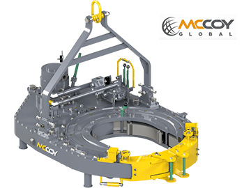
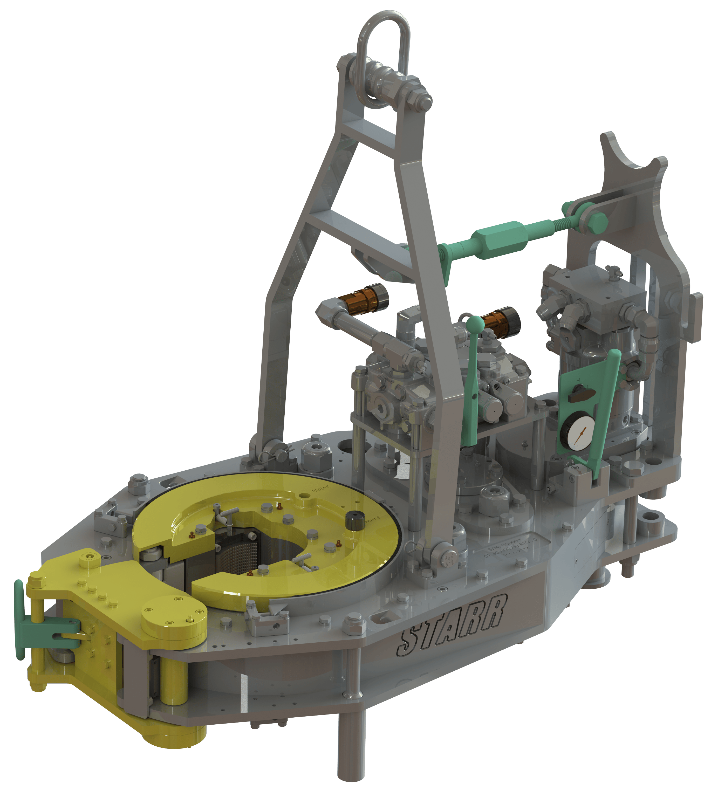
The HD26000 casing tong can handle tubulars as small as 10-3/4″ and as large as 26″ in diameter. Other sizes can be special-ordered. Tong can be mounted on either a CLINCHER® or a FARR® hydraulic backup. Available with McCoy’s patented WinCatt® data acquisition and torque control system for the make-up of tubular connections.
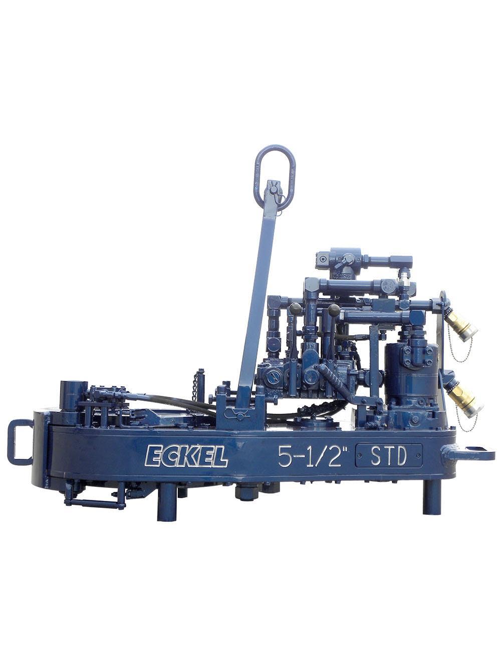
For casing up to 20 inches, here"s a tong that combines surprising speed with an ability to handle smaller sizes economically (as small as 7 inches). The 20 Standard reaches peak efficiency at just 38 horse power input, thus requiring no "souped-up" power unit. Available torque: 42,000 ft-lb
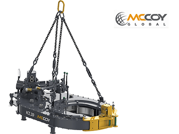
Versatility is the name of the game here as this tong works well whether powered by a workover rig or a portable casing tong power unit. Options include manual backup or cam-type hydraulic backups.
TThe Tri-Grip® Backup is the industry standard for reliable make-up and break-out of tubular connections that are optionally supplied with Eckel tongs. Utilizing two hydraulic cylinders and a three head arrangement ensures a slip-free operation. The backup is suspended at an adjustable level below the power tong employing three hanger legs and allows the backup to remain stationary while the power tong moves vertically to compensate for the connection"s thread travel. The Tri-Grip® uses two pivoting heads and one stationary. The Eckel Tri-Grip® Backup has exceptional gripping capabilities with Rig Dies when running drill pipe or optional Eckel Wrap-Around True-Grit® dies or Pyramid Fine Tooth dies for making up other types of tubular.
Model XQ28/2.6 hydraulic power tong is an improved type of XYQ1.8 which is used to make up and break out sucker rod thread in Well Service. This product has the following features:
A. The structure is compact, concise and light. Master tong is driven by a low-speed large torque hydraulic motor that matches with a manual control valve. The backup tong is just like a spanner. The total weight is approximately equal to XYQ1.8.
B. The operating is briefness and convenience with high efficiency. Put the respondence size jaw set into master tong and the respondence size glutting into backup tong, turning the reset knob incorrect direction then can make up and break out sucker rod by operating manual control valve. Two speed, snapping at low speed, spinning at high speed.
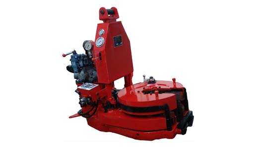
XQ140 micro-marking and no-marking hydraulic power tongs is a special equipment and open power tongs which is applicable to make up or break out 41/2"-51/2" casing during oil field work over operation. Master and back tong device adopts jaw plate type multi-point clamping mechanism.Can choose contour coated rig dies or pyramid tooth , to ensure the column minimum damage, and can improve the pipe thread connection quality, reduce due to improper work over pipe accident etc..
1. The tongs head is the open structure which is quick and convenient for entering and retreating working position. The integral tong head has good hardness and rigidity.
2. Master tong is roller climbing two jaw plate structure,can install arc tooth die ,the contact surface is more larger and clamp no deformation, The assembly and disassembly is very convenient. The optimum tangent-diameter ratio design ensures reliable clamping and easy slope retreating.The back tong is the three-jaw-plate structure pushed by hydraulic cylinder. The structure is simple and the clamping is reliable; The minimum damage to the tubular column can be ensured, and the main body of the pipe string can be clamped.
6. Master and back tong adopt integral frame structure,back tong is floating connection,The master and back tong adjustable distance, reduce the damage of pipe string shackle;
ATTO/PA/E y SUPPORTING AND POSITIONING MECHANISM FOR POWER TONGS Filed Jan. 28, 1965 J. L. FOSTER Nov. 29, 1966 2 Sheets-Sheet 2 (far/7a.; Zew/J Fa: fer
ATTOPMFLV United States Patent 3,288,000 SUPPORTING AND POSITIONING MECHANISM FOR POWER TONGS James Lewis Foster, P.O. Box 1351, Wichita Falls, Tex. Filed Jan. 28, 1965, Ser. No. 428,777 9 Claims. (Cl. 81-54) The invention relates to the connecting and disconnecting of sections of well pipe by means of power tongs and more particularly to mechanism for supporting and positioning power tongs for such use.
In the drilling of oil and gas wells it is customary to make use of power tongs for connecting and disconnect ing sections of drill pipe, such tongs usually being of a type having a frame formed at one end with a hollow housing provided with a central opening therethrough, and within which rotary head mechanism is rotatably mounted, to be driven by gear mechanism operated by a pressure fluid actuated motor carried on the frame. The rotary head mechanism includes means engageable with the pipe when the same is extended through the central opening to rotate the pipe with the mechanism and which is disengageable from the pipe to release the same.
In the use of tong mechanism of this kind, it has been customary heretofore to suspend the tong from above by a cable, the tong being supported by the cable in a position over the well bore with its central opening in axial alignment therewith for use in connecting and disconnecting sections of pipe, and being swung aside and lowered by the cable to a stand-by location when out of use. The use of such cable suspension means presents the disadvantage that the tong must be manually swung into and out of position for engagement with the pipe which greatly increases the labor and difiiculty in the use of the equipment. Moreover, the suspension of the tong for free swinging movement greatlyincreases the likelihood of injury to the user or damage to the mechanism.
The present invention has for an important object the provision of supporting and positioning mechanism for power tongs by which such tongs may be moved into and supported in an elevated position over the bore of a Well for use in rotating a section of well pipe in the connecting together or disconnecting of such sections of a string of pipe extending into the bore and moved aside from such position and supported in an out-of-use position laterally away from the bore when not in use.
Another object of the invention is to provide power tong supporting and positioning mechanism by which the position of the tong may be adjusted vertically while the same is supported horizontally above a well bore to allow the tong to be engaged with a section of well pipe at a desired location to permit the same to be rotated relative to another such section located below in connecting or disconnecting the sections.
3,288,000 Patented Nov. 29, 1966 lcg A further object of the invention is the provision of power tong supporting and positioning mechanism embodying means for movably supporting the tong for generally horizontal swinging movement into and out of position for engagement with a section of pipe to be connected into or disconnected from a string of pipe extending into a well bore and including means for allowing vertical rocking movement of the tong to permit angular adjustment of the tong relative to the pipe to accurately position the tong for gripping engagement therewith.
Briefly described the invention comprises power tong mechanism for connecting and disconnecting threaded joints of well pipe, including a power tong adapted to be grippingly engaged with a well pipe to rotate the same and supporting and positioning mechanism for the tong comprising inner and outer upright telescopingly arranged trackways and means for movably supporting the tong on the upper one of the trackways for horizontal swinging movement bodily about an axis common to the trackways to position the tong over the bore of a well for engagement with the pipe and means positioned for coaction with the trackways to import relative longitudinal movement to the trackways and to hold the trackways in a selected position of longitudinal adjustment relative to each other. By so supporting the tong, the tong may be moved bodily into a position over a well bore and adjusted to and held at a desired elevation for engagement with the pipe to rotate the same, and also moved bodily horizontally away from the well bore to clear the area around the pipe when the tong is not in use.
FIGURE 1 is a side elevational view of the invention illustrating a preferred embodiment of the same and showing the supporting and positioning mechanism with the tong supported in position for use in the rotation of a section of pipe;
FIGURE 3 is a side elevational view illustrating a different form of the supporting and positioning mechanism of the invention and showing the same with the tong supported in position for use; and
Referring now to the drawings in greater detail the invention is illustrated herein in connection with its use for the supporting and positioning of power tong mechanism of a conventional type, such as that employed in well drilling operations for the connecting and disconnecting of the sections of pipe of a well string. Tongs of this type, such as that illustrated in the drawings are commonly constructed with a main frame, generally designated 10 having at one end thereof a hollow housing 12, Within which rotary head mechanism is rotatably carried, to be driven through the intermediation of suitable gear mechanism or other means, not shown, enclosed in a casing 14 forming a part of the frame, and which is in turn driven by a motor 16, operable by pressure fluid from any convenient source of supply under the control of suitable valve means, not shown, of usual construction and arrangement. I The tong structure also commonly includes pipe holding or back-up means, such as that indicated at 18, which is constructed for engagement with a section of the pipe to hold the same against-rotation while the section above connected thereto is rotated by the tong to unscrew the section above therefrom. The holding or back-up device 18 may conveniently be connected to the frame of the tong by a supporting bar 20, as shown in FIGURE 1, which is in turn loosely connected to the frame, as by means of a bolt 22, slidably extended through a performation in the bore and which is surrounded by a coil spring 24 to allow limited movement of the back-up means relative to the housing 12 to permit the pipe gripping means of the tong and back-up means to position themselves properly on the pipe.
The bar 20, may be additionally supported for limited movement relative to the housing 12, by an adjustable bracket 26 of generally U-shape attached to the frame and through which the bar is loosely extended.
As illustrated in FIGURES 1 and 2, the tong supporting and positioning mechanism is of a type intended to be disposed in an opening in a supporting structure P, such as a derrick floor, drilling platform, or the like, for movement to an extended position with the tong at a desired location above the floor or platform or to a retracted position within the opening 0, as shown in FIG- URE 2. The supporting and positioning mechanism comprises an outer pair of parallel, vertically disposed side members 30, 30, having upper end flanges 32, 32 which are secured to the floor or platform as by means of bolts 34, with the members 30 extending downwardly in the opening 0 and connected together at their lower ends by a cross-piece 36.
The supporting and positioning mechanism also includes a telescoping framework made up of inner, parallel, spaced apart trackways 42, 42 and outer parallel, spaced apart trackways 44, 44, all of the trackways being of channel shape. The inner trackways 42, 42 are connected together at their upper ends by a cross-member or plate 46, and the outer trackways 44, 44 are connected together at their upper ends by cross-pieces, such as that shown at 48 in FIGURE 2 between which the inner trackways may move vertically.
Within the framework formed by the trackways, a hydraulic cylinder 62 is positioned centrally between the trackways with its lower end supported on the cross-piece 36 and with the upper end of its plunger 64 slidably extended into the lower end of a sleeve or spring cage 66 whose upper end is positioned to transmit an upward force to the plate 46 to lift the inner trackways 42, 42 upon actuation of the hydraulic cylinder. Within the sleeve 66 a coil spring 65 rests at its lower end on the upper end of the plunger 64 in position to transmit an upward force to the plate 46 at its upper end. The sleeve 66 thus forms a lost motion connection between the plunger 64 and the plate 46.
The power tong is supported on the plate 46, as by means of a rotatable connection, shown at 67, between a pair of channel members 68, 68 rotatably connected to the plate at one end and connected at their other ends to the frame 10 of the tong, as by means of a U-shaped element 70 having a pivotal connection at its bottom, as
The above described preferred embodiment of the invention is shown in FIGURE 2 in its fully lowered or retracted position, and when the tong is to be used for the connecting or disconnecting of sections of well pipe, the hydraulic cylinder 62 is actuated to lift the inner trackways 42, 42 and the tong therewith to the desired elevation, whereupon the tong may be moved 1 into position for use by rotating the tong bodily, horizontally about the connection 67 and also by rotating the tong about the connection 72. When the tong has 6 been positioned with the well pipe T extending through the hollow casing 12 and through the back-up mechanism 18, with the connected ends of the pipe sections 6 between the casing and back-up mechanism, the tong may be operated by the motor 16 to grippingly engage the pipe to unscrew the sections or to screw the same be moved upwardly and when the lower end flanges 58 engage the upper end flanges 60 of the outer trackways l the outer trackways will then be moved upwardly until the lower end flanges thereof engage the stops 54.
When the tong is not in use it may be swung aside I from its operating position above the well bore, by rotation about the connection 67, whereupon the tong may be further rotated about the connection 72 to position the tong in an out-of-the-way location until needed.
It will thus be seen that the form of the invention illustrated in FIGURES 1 and 2 provides a telescoping supporting and positioning mechanism whereby a power tong may be elevated and lowered to position the same at a desired elevation and whereby the tong may be moved horizontally and adjusted to position the same over a well bore or to move the tong aside when not needed for immediate use.
A somewhat different form of the invention is illustrated in FIGURES 3 and 4, wherein the support mechanism is mounted on the floor or platform P extending abovethe same. In this form of the invention the tong supporting and positioning mechanism includes an upright or post, generally designated 74 in FIGURE 3, comprising parallel, spaced apart channel members 76, 76 forming upright trackways, attached at their lower ends to a flat base 78, which is adapted to be secured to a drilling platform P or other supporting structure, as by means of bolts 80. The trackways 76, 76, may be connected to the base 78, by means of reinforcing angle plates, or the like, such as those shown at 82, 82, welded to the trackways and base or otherwise attached thereto.
A vertically movable carriage having parallel, spaced apart side plates 84, 84, connected by one or more crosspieces, such as that indicated at 86, is disposed between the trackways 76, 76, each of which plates is provided with upper and lower rollers, 88 and 90, respectively, rotatably connected thereto and extending between the flanges of the adjacent trackway for vertical rolling movement therealong. The carriage also has a cross-bar 92 connected at its opposite ends to the side plates 84 which serves as a slide rest upon which the tong rests between the trackways 7 6, 76, as best seen in FIGURE 3.
A hydraulic cylinder 94, similar to the cylinder 62, previously described, is centrally located between the trackways 76, 76 resting at its lower end on the base plate 78 and whose plunger is positioned to transmit an upward force to the carriage upon actuation of the cylinder to lift the carriage along the trackways, thereby elevating the tong therewith.
The supporting structure also includes opposite, parallel spaced apart channels 96, 96 connected at one end to the bottom of a U-shaped connector 100 whose arms are attached at their upper ends to the frame of the tong.
The side plates 84, 84 are also connected by a crosspiece 102 located mediate the ends of the plates, as shown in dotted lines in FIGURES 3 and 4 against which one end of a coil spring 104 is seated, whose other end bears against a downwardly extending lug 105 attached to the connector 100 and through which a rod 106 attached at one end to the connector is extended, the rod being slidably extended at its other end through the cross-piece 102. By this construction the tong may have some longitudinal sliding movement on the carriage between the trackways 7 6, 76 which movement is restrained by the spring 104 to hold the tong on the carriage and to allow some slight angular movement of the tong relative to the horizontal.
In making use of the above described form of the invention, illustrated in FIGURES 3 and 4, the tong is positioned on the carriage with the well pipe T extending through the hollow casing 12 and the back-up mechanism 18 of the tong as previously described, whereupon the tong may be elevated by supplying pressure fluid to the hydraulic cylinder 94 to position the tong for gripping engagement with the pipe at the desired location to efiect the unscrewing of sections of the pipe or the screwing together of the same.
It will be apparent that the tong may move horizontally somewhat relative to the carriage to allow the tong to adjust its position to the well pipe and that the tong may also tilt vertically somewhat to allow the tong to adjust itself to a position for gripping engagement with the pipe when the motor 16 is actuated to rotate the pipe. By this arrangement, in the event of some slight lateral movement of the pipe or angular movement of the same, the tong may adjust itself to compensate for such movements while remaining in tight gripping engagement with the pipe.
It will thus be apparent that the invention, constructed as described above, provides power tong supporting and positioning mechanism by which a power tong may be readily positioned at a desired elevation over the bore of a well or moved aside and supported in an out-of-theway position when out of use to make available a maximum space about the well bore for the carrying out of well operations.
1. In apparatus for connecting and disconnecting threaded joints in a well pipe string, the combination With a power tong adapted to be grippingly engaged with a well pipe to rotate the same, of supporting and positioning mechanism for the tong comprising inner and outer telescopingly arranged trackways, means for supporting the trackways in an upright position for longitudinal movement relative to each other adjacent a well bore, means for movably supporting the tong on the upper end of one of the trackways for horizontal rotational movement into and out of a position extending over the bore for engagement with the pipe, and means positioned for coaction with the trackways to impart relative longitudinal movement to and hold the trackways in a selected position of longitudinal adjustment relative to each other.
2. In apparatus for connecting and disconnecting threaded joints in a well pipe string, the combination with a power tong adapted to be grippingly engaged with a well pipe to rotate the same, of supporting and positioning mechanism for the tong comprising inner and outer telescopingly arranged trackways, means for supporting the trackways in an upright position for longitudinal movement relative to each other adjacent a well bore, means for movably supporting the tong on the upper end of one of the trackways for horizontal swinging movement bodily about an axis common to the trackways to position the tong over the bore for engagement with the pipe and means positioned for coaction with the trackways to impart relative longitudinal movement to and hold the trackways in a selected position of longitudinal adjustment relative to each other.
3. In apparatus for connecting and disconnecting threaded joints in a well pipe string, the combination with a power tong adapted to be grippingly engaged with a well pipe to rotate the same, of supporting and positioning mechanism for the tong comprising inner and outer telescopingly arranged trackways, means for supporting the trackways in an upright position for longi-- tudinal movement relative to each other adjacent a well bore, means for movably supporting the tong on the upper end of one of the trackways for horizontal swinging movement bodily about an axis common to the trackways and for rotational movement about an axis spaced horizontally from said common axis to allow the tong to be moved into and out of a position extending over the bore for engagement with the pipe and means positioned for coaction with the trackways to impart relative longitudinal movement to and hold the trackways in a selected position of longitudinal adjustment relative to each other.
4. In apparatus for connecting and disconnecting threaded joints in a well pipe string, the combination with a power tong adapted to be grippingly engaged with a well pipe to rotate the same, of supporting and positioning mechanism for the tong comprising inner and outer telescopingly arranged trackways, means for sup porting the trackways in an upright position for longitudinal movement relative to each other adjacent a well bore, means for movably supporting the tong on the upper end of one of the trackways for horizontal rotational movement into and out of a position extending over the bore for engagement with the pipe, and hydraulic means positioned for coaction with the trackways to extend the trackways to and hold the trackways in a selected position of extension relative to each other.
5. In apparatus for connecting and disconnecting threaded joints in a well pipe string, the combination with a power tong adapted to be grippingly engaged with a well pipe to rotate the same, or supporting and positioning mechanism for the tong comprising inner and outer telescopingly arranged trackways, means for supporting the trackways in an upright position for longitudinal movement relative to each other adjacent a well bore, means for movably supporting the tong on the upper end of one of the trackways for horizontal swinging movement bodily about an axis common to the trackways to position the tong over the bore for engagement with the pipe and hydraulic means positioned for coaction with the trackways to extend the trackways and hold the trackways in a selected position of extension relative to each other.
6. In apparatus for connecting and disconnecting threaded joints in a well pipe string, the combination with a power tong adapted to be grippingly engaged with a well pipe to rotate the same, of supporting and positioning mechanism for the tong comprising inner and outer telescopingly arranged trackways, means for supporting the trackways in an upright position for longitudinal movement relative to each other adjacent a well bore, means for movably supporting the tong on the upper end of one of the trackways for horizontal swinging movement bodily about an axis common to the trackways and for rotational movement about an axis spaced horizontally from said common axis to allow the tong to be moved into and out of a position extending over the bore for engagement with the pipe and hydraulic means positioned for coaction vw"th the trackways to extend the trackways and to hold the trackways in a selected position of extension relative to each other.
7. In apparatus for connecting and disconnecting threaded joints in a well pipe string, the combination with a power tong adapted to be grippingly engaged with a well pipe to rotate the same, of supporting and positioning mechanism for the tong comprising inner and outer telescopingly arranged trackways, means for supporting the trackways in an upright position for longitudinal movement relative to each other adjacent a well bore, means for movably supporting the tong on the upper end of one of the trackways for horizontal rotational movement into and out of a position extending over the bore for engagement with the pipe, and means for imparting relative longitudinal movement to the trackways to extend the trackways including hydraulically extensible means supported on an axis common to the trackways and yieldable means positioned for coaction with said extensible means and one of said trackways to yieldingly resist relative longitudinal movement of the trackways in a direction to retract the trackways.
8. In apparatus for connecting and disconnecting threaded joints in a well pipe string, the combination with a power tong adapted to be grippingly engaged with a well pipe to rotate the same, of supporting and positioning mechanism for the tong comprising inner and in a direction to extend the trackways and including yieldable means positioned to yieldingly resist relative longitudinal movement of the trackways in a direction to retract the trackways.
9. In apparatus for connecting and disconnecting threaded joints in a well pipe string, the combination with a power tong adapted to be grippingly engaged with a well pipe to rotate thesame, of supporting and posii tioning mechanism for the tong comprising inner and outer telescopingly arranged trackways, means for supporting the trackways in an upright position for longii tudinal movement relative to each other adjacent a well bore, means for movably supporting the tong on the upper end of one of the trackways for horizontal swing ing movement bodily about an axis common to the trackways and for rotational movement about an axis spaced horizontally from said common axis to allow the tong to be moved into and out of a position extending over the bore for engagement with the pipe and extensible means positioned for coaction with the trackways to impart relative longitudinal movement to the trackways in a direction to extend the trackways and including yieldable means positioned to yieldingly resist relative longitudinal movement of the trackways in a direction to retract the trackways.
Our experienced and skilled power tong technicians play a major role in the safety and efficiency of a casing run. This makes the selection of your power tong service company a key component of overall performance.
ProTorque attracts and employs some of the industry’s most talented and experienced casing running technicians. Every detail of a casing run must be considered when looking for cost savings and efficiency; particularly on long production strings where every second counts while maintaining a safe operation. When making-up hundreds of connections, filling on the fly and selecting the correct handling equipment (air or hydraulic powered slips); we save time and effort on long challenging casing runs. ProTorque can meet handling requirements of up to 500 tons of hoist capability.
New Carter Tool Co. Inc. M-Series 2.0 power sucker rod tong, complete with spring hanger assy., gate assy., front end control assy., pressure gauge assy., two 90 degree XH street ells, one set of size equipment and safety sling with clevis.
New Carter Tool Co. Inc. M-Series 4.0 power sucker rod tong, complete with spring hanger assy., gate assy., front end control assy., pressure gauge assy., two 90 degree XH street ells, one set of size equipment and safety sling with clevis.
New Carter Tool Co. Inc. M-Series 5.0 power sucker rod tong, complete with spring hanger assy., gate assy., front end control assy., pressure gauge assy., two 90 degree XH street ells, one set of size equipment and safety sling with clevis.
New Carter Tool Co. Inc. M-Series 5.5 power sucker rod tong, complete with spring hanger assy., gate assy., front end control assy., pressure gauge assy., two 90 degree XH street ells, one set of size equipment and safety sling with clevis.
New Carter Tool Co. Inc. M-Series 7.5 power sucker rod tong, complete with spring hanger assy., gate assy., front end control assy., pressure gauge assy., two 90 degree XH street ells, one set of size equipment and safety sling with clevis.
Our power tongs are built to last. With 1 motor options for the 6 1/4” hydraulic power tong, you crew can reach rated torque at 2500 psi. Which means, the tools can reach their rated torque dependably on ever single joint, every day.
With an investment like this, you don’t want one malfunctioning part to be the reason why your equipment isn’t performing. That’s why we build our tongs to be serviceable, high in quality. By using an ISO 9001:2015 quality system, we maintain a close eye on our products.


 8613371530291