
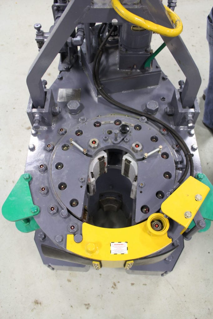
power tong frame top view manufacturer
The Eckel Top Drive Casing Tong is a tool developed for use on hydraulic top drive rigs to provide a high quality connection while reducing tubular damage and providing a safer enviroment for crews. With an operating capacity of 4 1/2 inch through 10 5/8 inch, is connected to the output stem of the power swivel. After installation the tong becomes an integral part of the swivel, raising and lowering as a unit and transfering the power swivel"s RPM and torque to the pipe/connection.
A guide attached beneath the top drive tong simplifies alignment of the collar within the tong. Once the collar of the pipe is enclosed within the top drive tong, the tong will grip the collar by operating the power swivel. Torque and rotational speed are controlled through the operation of the power swivel. Reversal of the power swivel will cause the tong jaws to release. Tong jaws are spring loaded to retract away from the collar.
Utilizing three gripping jaws and a patented Eckel Cam Biting System to grip the pipe collar. The same type of proven biting system found in the industry leading Eckel Power Tongs. These jaws are spaced evenly about the circumference of the collar to provide even distribution of the gripping forces

Except for added torque (up to 25,000 ft-lb) and expanded pipe capacity (from 4 to 13⅜ inches), the 13⅜ Standard tong offers the same basic engineering and designs the smaller, lighter Model 10¾. Highly recommended where applications demand the ultimate in a size range and torque output.
The Tri-Grip® Backup is the industry standard for reliable make-up and break-out of tubular connections that are optionally supplied with Eckel tongs. Utilizing two hydraulic cylinders and a three head arrangement ensures a slip-free operation. The backup is suspended at an adjustable level below the power tong using three hanger legs and allows the backup to remain stationary while the power tong moves vertically to compensate for the connection"s thread travel. The Tri-Grip® uses two pivoting heads and one stationary. The Eckel Tri-Grip® Backup has exceptional gripping capabilities with Rig Dies when running drill pipe or optional Eckel Wrap-Around True-Grit® dies or Pyramid Fine Tooth dies for making up other types of tubular.
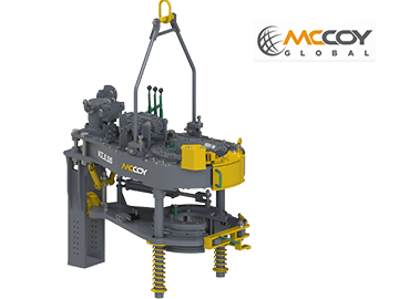
The HD26000 casing tong can handle tubulars as small as 10-3/4″ and as large as 26″ in diameter. Other sizes can be special-ordered. Tong can be mounted on either a CLINCHER® or a FARR® hydraulic backup. Available with McCoy’s patented WinCatt® data acquisition and torque control system for the make-up of tubular connections.
#Jflw ATTORNEYS vgh hsheneh hshsh hehsh M8- United States PatentO JAW OPERATING MEANS FOR POWER TONGS Archie W. Beeman and Clarence D. New, Odessa, Tex. Application December 9, 1957, Serial No. 701,408
7 Claims. (Cl. 81-53) This invention relates to power tongs of the type commonly used in oil fields for making and breaking threaded connections between pipes, cylindrical drilling tools, and the like.
In oil field operations it frequently is necessary to connect or disconnect the ends of long sections of large diameter pipes, and in many instances such connections are established by means of threaded joints. As an example, drill pipes customarily constitute a series of long pipe sections threadedly connected at their adjacent ends. Since these pipe sections are very heavy and since they have large outside diameters, special equipment is required in order to rotate them relative to each other inmaking or breaking the threaded connections between adjacent sections. Power tongs are well suited to this type of service. A typical power tong includes some means for firmly gripping the external surface of a pipe section and means for rotating the pipe section while so gripped.
A number of tong constructions have been proposed heretofore, but these have been complicated and expensive pieces of equipment. The pipe-gripping means employed in these prior constructions have been particularly elaborate, and the presence of large numbers of relatively movable parts has adversely affected the reliability of such equipment.
An object of this invention is to overcome the foregoing objections and to provide an inexpensive power tong construction which will efiiciently make or break threaded pipe joints without endangering the lives of the working crewmen.
These objects are realized in a power tong construction which includes an elongated frame having a pipe-gripping mechanism at one end and a power unit at the other. Power is transmitted from the power unit to the pipegripping mechanism through a series of roller chain and sprocket combinations which serve as speed-reduction means.
The pipe-grippin mechanism cooperates with a throat in the end of the frame for the reception of a pipe section to be rotated. It includes a partial ring rotatably mounted upon the frame of the tong and having an opening which may be aligned with the throat so that the pipe section may be disposed within the ring. This ring may be driven in either direction by a roller chain cooperating with a sprocket fixed to the ring and connected to the speed-reducing means.
Fig. 1 is a plan view of a power tong according to the invention, with the top plate of the frame removed and with certain parts being broken way to illustrate features I of the construction;
The main frame of the illustrated power tong construction has been designated generally by the numeral 2. It includes the top wall 4 and a bottom wall 6 held in spaced apart relation by any suitable means. The frame 2 also may include side walls to protect the internal mechanisms against the entrance of dirt and other foreign materials, but these side walls have been omitted from the drawings in the interest of clarity.
At its front end the frame 2 is provided with a throat 8 through which a pipe section P may pass into cooperative relationship with respect to a pipe-gripping mechanism to be described in greater detail below. It will be understood as the description proceeds that the term pipe section is used herein in a generic sense, to refer to bodies of various kinds having generally cylindrical exterior surface portions which may be gripped by the tong. Such bodies may be sections of drill pipe, casing, tubing, rods, tools, etc.
Mounted upon the frame 2 adjacent the throat 8 are upper and lower arcuate bearing members 10 and 12 (Fig. 2). The upper bearing member 10 is fixed rigidly to the forward edge of the top plate 4 of the frame 2 by means of a plurality of screws 14 cooperating with threaded holes 16 in the top member, and the lower bearing member 12 is secured rigidly to the bottom plate 6 in a similar manner by screws 18 cooperating with threaded holes 20 in the lower bearing member 12. As best shown in Fig. 1, the upper bearing member 10 is interrupted at the throat 8 of the frame 2 to prevent interference with the passage of the pipe section P into the pipe-gripping mechanism. It will be understood, of course, that the lower bearing member 12 is similarly interrupted.
Referring particularly to Fig. 1, it will be seen that the partial ring 22 and the sprocket 32 include gaps or openings 33 and 34 which are comparable in extent to the throat 8 of the frame 2. These openings 33 and 34 are brought into alignment with the throat 8 during move ment of the pipe section P into or out of the tong.
The partial ring 22 may be rotated relative to the frame 2 by means of a roller chain 35 which engages the periphery of the sprocket 32 and is driven. by a sprocket 36. The path of the drive chain 35 is established Patented Mar. 31,
i: i asvaeso suitable. idler sprockets 38 mounted upon the frame 2. If desired, certain or all of these idler sprockets 38 may be adjustably mounted upon the frame 2 so that slack in the drive chain 34 may be removed by slight changes intheir positions. As indicated in Fig. 1, it is preferred that each of the idler sprockets 38 be mounted upon antifriction bearings 40, but this is not essential in all cases.
The drive sprocket 36 is carried by a sleeve 42 rotatably mounted upon a bearing post 44 by suitable antifriction bearings 46. The upper end portion of the sleeve 42 carries a sprocket 48 of greater diameter than the drive sprocket 36. Since both of these sprockets 36 and 48 are secured rigidly to the sleeve 42, they must rotate as a unit and the peripheral speed of the large sprocket 48 is considerably greater than the peripheral speed of the smaller drive sprocket 36. It will be seen therefore that the sleeve 42 and the two sprockets 36 and 48 constitute a reliable and simple speed-reducing means for the drive system of the power tong of this invention.
The sprocket 48 is driven through a similar speedreducing means disposed rearwardly thereof along the frame 2. This second speed-reducing means includes a small sprocket 50 connected to the large sprocket 48 by a roller chain 52, a sleeve 54 rotatably mounted upon a rigid post 56, and av large sprocket 58. The large sprocket 58 is driven through a roller chain 60 by a small sprocket 62 carried by a drive shaft 64 at the rear end of the frame 2.
It is preferred that the bearing posts 44 and 56 be provided with channels 65 leading from lubricant fittings or nipples 66 at the exterior of the frame 2. This arrangement greatly simplifies the maintenance operations required in order to keep the equipment in good condition.
Attention also is invited to the fact that in the illustrated construction the bearing posts 44 and 56 serve the additional purpose of increasing the rigidity of the frame 2. Each of the posts 44 and 56 has a threaded upper end portion 67 detachably connected to the top wall 4 of the frame 2, and a threaded lower end portion 68 for receiving a nut 69 which bears against the lower face of the bottom wall 6 of the frame 2. Disposed immediately below the threaded upper portion 67 of each of the bearingposts is a shoulder 70 in position to bear against the lower face of the top wall 4. Similarly, a shoulder 71 adjacent the lower threaded portion 68 of each bearing post bears against a washer 72 resting upon the upper face of the bottom wall 6 of the frame 2. When the nuts 69 are tightened, therefore, the spacial relationship between the top and bottom walls 4 and 6 is fixed.
The bearing posts for the idler sprockets 38 preferably are of similar construction, and if desired, the several bearing posts may constitute the sole means for connecting together the top and bottom walls 4 and 6 of the frame 2.
A brief description of the mode of operation of the tong of this invention may be helpful. It will be understood that initially the openings 33 and 34 in the partial ring-22 and the sprocket 32 are aligned with the throat 8 in the frame 2 so that the pipe section P may be inserted into the interior of the partial ring 22. When so inserted, the exterior surface of the pipe section P comes into contact with the serrated edges of the fixed dies 100 on the die carrier 79, and the axis of the pipe section P is approximately coincident with the axis of rotation of the partial ring 22. After the pipe section P is in position, power is applied to the motor shaft 76 to rotate the partial ring 22 in either direction. As an example, it may be assumed that the motor shaft 76 is rotated so as to cause the partial ring 22 to move in a clockwise direction in Fig. 1.
After the pipe section P has been rotated sufficiently, the tong may be freed from the pipe section P by rotating the ring 22 a short distance in a counterclockwise direction, to position the low points of the cam surfaces 110 and 112 opposite the cam followers 114 and 116, respectively. With the parts in such positions, the movable dies 102 and 104 may be disengaged from the pipe section P, and the tong may be moved rearwardly slightly to free the fixed dies 100 from contact with the surface of the pipe section P. Thereafter, the ring 22 may be rotated in either direction to position its opening 33 in alignment with the throat 8 of the tong so that, the pipe section P may pass out of the tong.
1. A power tong for rotating a pipe comprising a frame having a throat for the reception of a pipe, said frame including top and bottom members spaced from each other and terminating at said throat, an arcuate lower bearing member fixed to said bottom member adjacent said throat, an arcuate upper bearing member fixed to said top member adjacent said throat above and spaced from said lower bearing member, partial ring means hearing against the vertical faces of said bearing members and including a portion disposed between and contacting the adjacent faces of said bearing members, means for rotating said partial ring means relative to said bearing members, and pipe-gripping means carried by said partial ring means in position to engage the surface of a pipe disposed within said throat so as to rotate the pipe upon rotation of said partial ring means.
2. A power tong for rotating a pipe comprising a frame having a throat for the reception of a pipe, said frame including top and bottom members spaced from each other and terminating at"said throat, an m tate and-the links 106 and 108 are so mounted that the earn surfaces 110 and 112 urge these movabledies102 and- 104 In this construction lower bearing member fixed to said bottom member adjacent said throat, an arcuate upper bearing member fixed to said top member adjacent said throat above and spaced from said lower, bearing member, partial ring means bearing against the inner and outer vertical faces of said bearing members and including a portion disposed between and contacting theadjacent faces of said bearing members, sand partial ring means being provided with an opening therein which may be brought into alignment with said throat so that the pipe may be disposed within said ring means, a sprocket fixed to said partial ring means inwardly of said bearing members and having an opening therein in alignment with said opening in said ring means, a drive. chain engaging a portion of the periphery of said sprocket spaced from said throat for rotating said partial ring means relative to said bearing members, and pipe-gripping means carried by said partial ring means in"position to engage the surface of a pipe disposed within said partial ring means so as to rotate the pipe upon rotation of said partial ring means.
3. A power tong for rotating a pipe comprising a frame having a throat for the reception of a pipe, a partial ring rotatably mounted on said frame and having a side opening therein which may be brought into alignment with said throat so that a pipe may be disposed within said ring, means for rotating said ring about its central axis, i die means carried by said ring at a location opposite said opening, "said ring being provided with a cam surface movable therewith, and means movable by said cam surface upon rotation of said ring for bearing against a pipe disposed within said ring in such a direction as to cause said die meansto grip said pipe.
4. A power tong for rotating a pipe comprising a frame having a throat for the reception of a pipe, a partial ring rotatably mounted on said frame and having a side opening therein which may be brought into alignment with said throat so that a pipe may be disposed within said ring, the inner surface of said ring including a pair of cam surfaces disposed on opposite sides of the center line of said opening, the centerline of said opening and a line perpendicular thereto and passing through the axis of said ring dividing a circle about said axis into four quadrants, an arcuate die carrier rotatably mounted upon said ring and being disposed with the two quadrants of said circle opposite said opening in said ring, a first pair of dies fixed to said carrier and disposed respectively in said two quadrants, a second pair of dies mounted on said carrier for movement in generally radial directions and disposed respectively in the two quadrants of said circle adjacent said opening in said ring, and means cooperating with the dies of said second pair and with said cam surfaces to move said dies of said second pair radially inwardly upon rotation of said ring relative to said carrier.
5. A power tong for rotating a pipe comprising a frame having a throat for the reception of a pipe, a partial ring rotatably mounted on said frame and having a side opening therein which may be brought into alignment with said throat so that a pipe may be disposed within said ring, the inner surface of said ring including a pair of arcuate depressions which form cam surfaces disposed on opposite sides of the center line of said opening, means for rotating said ring about its central axis, a bearing rail fixed to the inner surfaces of said ring at a location opposite said opening and having grooves in its upper and lower surfaces, an arcuate channel-shaped die carrier mounted upon said bearing rail for rotation relative to said ring and being provided with hearing means projecting into said grooves, a pair of link means pivotally connected to the ends of said carrier and including portions projecting into said arcuate depressions in the inner surface of said ring, a first pair of pipe-gripping dies fixed .to said carrier, and a second pair ofpipe-gripping dies rotatably mounted on said frame and having a side open "ing therein which maybe brought into alignment with said throat so that a pipe may be disposed within said ring, the inner surface of said ring including a pair of arcuate depressions which form cam surfaces disposed on opposite sides of the center line of said opening, means for rotating said ring about its central axis, a bearing rail fixed to the inner surface of said ring at a location opposite said opening and having grooves in its upper and lower surfaces, an arcuate channel-shaped diecarrier mounted upon said bearing rail for rotation relative to said ring and being provided with hearing means projecting into said grooves, a pair of link means pivotally connected to the ends of said carrier, a rotatable cam follower carried by each of said link means and projecting into "said arcuate depressions in the inner surfaces of said ring so that, upon rotation of said ring relative to said carrier in either direction, said link means are pivoted to move portions thereof closer to the axis of rotation of said ring, a"first pair of pipe-gripping dies fixed to said carrier in position to engage a pipe disposed within said ring, and a second pair of pipe-gripping dies fixed to said portions of said link means in position to press against the surface of the pipe under the influence of said cam surfaces and to urge said pipe toward said first pair of dies.
7. A power tong for rotating a pipe comprising a frame having a throat for the reception of a pipe, a partial 8 ring rotatabty mounted on saidframe andhavin"g aside opening therein which may be brought into alignment with said throat so that a pipe maybe disposed within said ring, means for rotating said ring about its central axis; diemeans carried by said ring at a location opposite said opening, said ring being provided with cam surfaces disposed on opposite sides of the center line of said opening, a pair of die means each disposed approximately 90 degrees from said first-mentioned die means and on opp"osit"e sides of said center line of said opening, rotation of said ring causing said cam surfaces to engage said pair of die means to move said pair of die means inwardly to grip said pipe on opposite sides thereof for sequential turning movement of said pipe.
Embodiments of the present disclosure relate, generally, to apparatus and methods for making up and breaking out wellbore tubulars and, more particularly, to an integrated, electric tong system and methods of use at a wellbore. BACKGROUND
In the oil and gas industry, oil field tools, such as tongs or wrenches, are used to grip and rotate joints of tubulars (e.g., casing, drill pipe, other tubulars), particularly during makeup operations (e.g., threadably engaging, screwing together) or break-out operations (e.g., threadably disengage, unscrew). These oil field operations typically require a set of tongs, including an upper tong, which can be used to rotate an upper tubular for threadably connecting the upper tubular to, or removing the upper tubular from, a lower tubular, and a lower tong, which can be used to secure and hold stationary a lower tubular, to prevent its rotation in conjunction with the rotating upper tubular. The upper tong is commonly referred to in the industry as a power tong. The power tong comprises a mechanism or various components for gripping and rotating a tubular, while the body or housing of the power tong remains stationary. The lower tong is commonly referred to in the industry as a backup tong, and is used, as set forth above, for securing and holding a tubular stationary.
Typically, power tongs are hydraulically driven, which can include the use of hydraulic hoses connecting the power tongs to a hydraulic power unit or source for actuating or powering the jaws of the power tong. Valves are typically used to control the flow of hydraulic fluid or oil to the power tongs, for providing power to the power tong and gearbox, which in turn, operates the jaws of the power tongs for closing around a tubular and rotating the tubular. This type of hydraulic system, for powering the power tongs, can generally lack precision in the operation of the tongs, including the control of the speed of the rotation of the tongs and the torque applied to the tubular. In addition, this type of hydraulic system can pose environmental concerns, which can be associated with a leakage or spillage of the hydraulic oil.
In addition, the combinations of hydraulically powered power tongs and backup tongs are cumbersome and heavy tools. As such, hydraulic lift cylinders are typically required for moving and supporting the power and backup tongs, particularly when making up or breaking out a string of tubulars. Although existing units have combined a power tong with a backup tong, the lift cylinders are generally added, when rigging up in the field and operated separately.
Therefore, a need exists for an electric tong system that can be packaged and integrated into a single system, comprising a power tong, a backup tong, and a lift assembly, for minimizing rig-up time and expenses.
A need exists for an integrated electric tong system comprising a power tong, a backup tong, and a lift assembly, in which the motors for the power tong, backup tong and lift assembly can be operated and controlled by the use of a single driver. The electric tong system will enable greater precision in controlling the speed, torque, and direction of the rotation of the power tongs.
A need exists for an integrated electric tong system and methods of use comprising a power tong, backup tong and lift assembly, wherein the backup tong includes automated control for enabling greater precision in the movement of the backup tong components as well as the clamping and gripping of tubulars. In addition, a need exists for an automated electric tong system, comprising interlocking, capabilities for providing remote operation and additional safety features.
A need exists for an integrated electric tong system and methods of use comprising automation for remote operation of the electric tong system and for monitoring and analyzing the turns and torque data.
Embodiments of the present disclosure relate, generally, to an integrated, electric tong system that can be usable for threading and unthreading tubular members at a wellbore. The electric tong assembly can include a frame assembly that can comprise an upper frame and lower frame, wherein the lower frame can include a first vertical member and a second vertical member. At least one actuator can be connected to the upper frame and the lower frame for moving the upper frame with respect to lower frame, and the at least one actuator can be driven by a first electric motor. In an embodiment, the at least one actuator is a linear actuator. In an embodiment, the upper frame can comprise a U-shaped frame that can be moved telescopically in relation to the lower frame.
The electric tong system can further include a backup tong that can be connected to the lower frame, wherein the backup tong can be driven by a second electric motor and can comprise a central opening for receiving a lower tubular member, such that the backup tong can receive, clamp and grip the lower tubular member during threading or unthreading operations. The electric tong system can further include a power tong that can be connected to the backup tong, and the power tong can include a central opening for receiving an upper tubular member. The power tong can be driven by a third electric motor and can be used for gripping and rotating the upper tubular member during threading or unthreading operations. In an embodiment of the electric tong system, a single driver is used for controlling the first electric motor, the second electric motor and the third electric motor of the electric tong system.
The power tong can include a housing that comprises an opening, and a rotary mechanism located within the housing that also comprises an opening. The power tong can further include a plurality of jaws and a ring gear that can be operably connected to the third electric motor of the electric tong system. The power tong housing can include a door that can be rotatably connected to the housing and located proximate to the opening of the housing, wherein the opening of the housing and the opening of the rotary mechanism can align to comprise the central opening of the power tong. The power tong can further include a plurality of sensors that can be usable for sending a signal to actuate the plurality of jaws to secure the upper tubular member, when the openings of the housing and rotary mechanisms are aligned and the power tong door is closed. In an embodiment, the ring gear and rotary mechanism can be used to transfer torque from the third electric motor to the upper tubular member when the plurality of jaws are actuated.
The backup tong of the electric tong system can be usable for clamping and gripping a tubular member during threading and unthreading of the tubular member, for example, during make-up and break out operations. The backup tong can comprise a frame that partially defines a central opening that can receive the tubular member for threading or unthreading of the tubular. A door can be rotatably connected to the frame, and the door can rotate between an open position and a closed position, and partially define the central opening. A first linear actuator can be connected to the frame and to the door for use in rotating the door between the open position and the closed position. A latching arm can be rotatably connected to the frame, wherein the latching arm can latch the door in the closed position, and a second linear actuator can be connected to the frame and to the latching arm, wherein the second linear actuator an rotate the latching arm to latch the door in the closed position, and wherein the rotation of the latching arm progressively increases a force of contact between the door and the tubular member. The second linear actuator can be driven by an electric motor, and sensors can be operably connected to the first linear actuator and the second linear actuator for detecting the positions of the linear actuators and for activation/deactivation of the linear actuators.
The backup tong can further comprise a load cell, which can be located within the frame, and a J-shaped load transfer member that can include a first end connected to the load cell and a second end connected to the second linear actuator. In an embodiment, the load transfer member can be pivotably connected to the frame assembly and can transfer a proportion of force received from the second linear actuator to the capacity of the load cell.
In an embodiment of the backup tong, the frame can include at least one guide plate, and the second linear actuator can comprise at least one protrusion that can intersect with the at least one guide plate of the frame. In another embodiment of the backup tong, the central opening can be further defined by at least one gripping member for gripping the tubular.
Embodiments of the present invention can include a method for removing a plurality of tubulars from a wellbore, wherein the method steps can include: positioning an electric tong system onto a joint of tubulars, wherein the electric tong system can include: a frame assembly; a backup tong comprising a first opening, a first door, and a latching arm; and a power tong comprising a second opening, a second door, and a plurality of jaws. The joint of tubulars ca include an upper tubular connected to a lower tubular with a connector.
The steps of the method can continue by adjusting the frame assembly for aligning the first opening of the backup tong with the second opening of the power tong. The aligned backup tong can grip the lower tubular, and the aligned power tong can grip the upper tubular. The method can further include closing the first door and second door, wherein the first door can trigger a linear actuator to compress the first door against the connector, and the second door can trigger the plurality of jaws to compress the upper tubular against a rotary mechanism and operably connect the rotary mechanism to an electric motor through a low transfer gear. The steps of the method can further include rotating the aligned power tong until the upper tubular is disconnected from the lower tubular, and aligning the rotary mechanism with the second opening for opening the second door. The method can conclude by de-energizing the linear actuator to open the first door, and removing the upper tubular from the wellbore. The method steps can be repeated, as needed, for removing the plurality of tubulars from the wellbore.
In an embodiment, the step of closing the first door can further include actuating a second linear actuator, which can be connected to the frame assembly and to the latching arm, for rotating the latching arm to latch the first door in a closed position. The rotating of the latching arm can progressively increase a force of contact between the first door and the lower tubular.
In an embodiment, the interlock system of the electric tong system can include preventing the rotation of the aligned power tong, for disconnecting the upper tubular from the lower tubular, until after the first door has been closed. In addition, the interlock system can include locking the frame assembly in place and preventing any adjustments thereto until the first door has been opened. Further, the interlock system of the electric tong system can enable the performance of only one of the following steps at a time, including: adjusting the frame assembly, compressing the first door, or rotating the power tong. BRIEF DESCRIPTION OF THE DRAWINGS
FIG. 6A is a perspective, cutaway view of an electric motor and brake assembly for a backup tong in accordance with one embodiment of the present invention.
FIG. 9 is a perspective view of an electric tong system, driver box, and flush mounted spider in accordance with one embodiment of the present invention.
FIG. 15B is a side view schematic of the no side load reaction system for the tong system in FIG. 15A, in accordance with one embodiment of the present invention.
FIG. 15C is a plan view schematic of a horizontal member of the no side load reaction system for the tong system in FIG. 15A, in accordance with one embodiment of the present invention.
FIG. 15D is a plan view schematic of a tong of the no side load reaction system for the tong system in FIG. 15A, in accordance with one embodiment of the present invention.
FIG. 15E is a side view schematic of the reaction post of the no side load reaction system for the tong system in FIG. 15A, in accordance with one embodiment of the present invention.
As well, the drawings are intended to describe the concepts of the invention so that the presently preferred embodiments of the invention will be plainly disclosed to one of skill in the art, but are not intended to be manufacturing level drawings or renditions of final products and may include simplified conceptual views as desired for easier and quicker understanding or explanation of the invention. As well, the relative size and arrangement of the components may differ from that shown and still operate within the spirit of the invention as described throughout the present application.
Moreover, it will be understood that various directions such as “upper”, “lower”, “bottom”, “top”, “left”, “right”, “inward”, “outward” and so forth are made only with respect to explanation in conjunction with the drawings, and that the components may be oriented differently, for instance, during transportation and manufacturing as well as operation. Because many varying and different embodiments may be made within the scope of the inventive concept(s) herein taught, and because many modifications may be made in the embodiments described herein, it is to be understood that the details herein are to be interpreted as illustrative and non-limiting.
Embodiments of the present disclosure relate, generally, to an apparatus and methods for making up and breaking out tubular joints and, more particularly, to an integrated, electric tong system and methods of use at a wellbore. The integrated electric tong system comprises a power tong, a backup tong, and a lift system (e.g., two actuators, a gearbox, a brake, an electric motor, interconnecting components and a telescopic frame), which are integrated into a single package and operated by electrical motors that can be controlled by a single driver.
The apparatus can include the use of switchgears and contactors for enabling the use of the single driver to control and operate the individual electric motors of the power tong, backup tong, and the lift system, as described above. The driver comprises the electronics and firmware required to control the speed and direction of the electric motor(s), and the driver can be housed in a separate aluminum box (i.e., driver box) that can be positioned in a safe area (i.e., nonhazardous area), away from the electric tong system.
The backup tong is located below the power tong of the electric tong system, and comprises a pneumatic cylinder for operation of a backup door. An electric motor can be mounted on the backup tong for operating a latch, located on the backup tong, which can be used for locking the backup door and applying a clamping force to a lower tubular during make-up or break-out operations. While the backup tong clamps and holds the lower tubular stationary, the power tong can rotate the upper tubular, which allows the power tong to apply torque to the connection joint between the upper tubular and the lower tubular.
The backup tong, which is used for the clamping of the lower tubular, can comprise a backup door(s) that can be closed pneumatically (i.e., use of a pneumatic cylinder) and tightened electrically. Specifically, an electric linear actuator can be used for applying a clamp force to the lower tubular, during make-up or break-out of the tubular joint connections. The clamp force can be sensed and measured by an electronic tension load cell that can be located in the backup tong and connected to a “J-shaped” member that can be pivotally connected to the backup case. A first end of the “J-shaped” member can be connected to the electrically-operated linear actuator, while a second end of the “J-shaped” member can be connected to the electronic tension load cell. The “J-shaped” member can be a lever that is used for proportioning the force from the electric linear actuator to the capacity of the electronic tension load cell.
In an embodiment of the electric tong system, the power tong can be located above the backup tong, and can be a conventional or hydraulic tong that is retrofitted to operate via an electric motor. The motor operating the power tong can be a servo-type motor that provides precise application of torque and speed. In an embodiment, the power tong is attached to a frame, which can be extended and retracted by an electrically operated lift system, as described above, for allowing vertical movement of the electric tong system.
Unlike conventional tongs, the automation of the electric tong system enables the operation of a selected sequence of functions through a single actuation (i.e., a push of a button can close the power tong door, latch the backup door and rotate the power tong). An operator box, which can be located at various positions on or about the electric tong system, including on the power tong, at the bottom of the tong, or on a floor stand, and remotely positioned with respect to the electric tong system, can be used to operate all of the functions on the electric tong system, including tong door open/close, backup open/close, lift up/down, high/low gear, rotate/cage plate align, manual/automatic mode, and make/break direction. In an alternative embodiment, the electric tong system can be operated remotely. A computer or computerized system can be used to monitor, receive and analyze the functions and output of the power tong, backup tong, and the lift cylinder of the electric tong system.
The automated and/or remote operation of the electric tong system provides many unique and/or safety features, including: (a) operation of the electric tong system from the rig floor or remotely (hand controller) to eliminate the need for an operator to be located on an operator stand (e.g., scaffolding) and the potential danger to the operator; (b) greater precision with regard to the control of the speed and direction of the motor(s) for the power tong and backup tong; (c) better torque control of the joint connection; (d) elimination of hydraulic power usage and related environmental issues; (e) safer operation during make-up and break-out operations by capability of an enhanced interlocking system; (f) Torque Turn system built into electric tong system for monitoring and analyzing data regarding the number of turns and the torque amount, with or without the use of a computer to record connections; (g) the transport footprint is about the same as a standard tong apparatus; (h) no side load reaction system; and (i) the ability to retrofit a conventional hydraulic tong with an electric motor and a gearbox to form the electric tong system.
Referring now to the drawings and more particularly to FIGS. 1-2, the Figures show an embodiment of a tong system (10) for making up or breaking out a string of tubulars, such as casing, drill pipe, or other tubulars. In this embodiment, the tong system or electric tong system (10) comprises a frame (12) that can comprise a generally U-shaped member (14) in telescoping engagement with frame members (16 a, 16 b), which can extend vertically in a generally parallel configuration. The frame may comprise horizontal base members (18 a, 18 b) that allow the electric tong system 10 to stand upright. The lower ends of the frame members (16 a, 16 b) may be rigidly attached to the base members (18 a, 18 b), while the upper ends of the frame members (16 a, 16 b) are attached to the U-shaped member, which can be connected to a lifting bracket (15). The frame members (16 a, 16 b) can be tubular or solid. Alternate embodiments of the frame assembly for the electric tong system are shown in FIGS. 16 and 17. The tong system (10) may be lifted via lifting lugs (20) through an adjustment screw formed on a top portion of the lifting bracket (15).
In this embodiment, a backup tong (30) is mounted to horizontal support beam(s) that attach(es) to the frame members (16 a, 16 b) and/or base members (18 a, 18 b). In an alternate embodiment, the backup tong can attach to a second or lower U-shaped member, which can attach to the lower end of the vertical frame members (16 a, 16 b) and/or the base members (18 a, 18 b). The backup tong (30), as shown in this embodiment of the electric tong system, will be further described in subsequent Figures. The power tong (50) and backup tong (30) can be connected to each other by a post (52) (e.g., torsion post), extending therebetween.
Conventional power tongs can include an “open throat” tong, in which the body and ring gear of the tongs have a window or opening for permitting a pipe or other tubular to be moved into and out of the central opening of the ring gear. Other conventional power tongs include a closed throat configuration, in which a pipe or other tubular must be inserted longitudinally into a ring gear opening. Open throat tongs typically have a gear train comprising two or more idler gears, while closed throat tongs may omit the idler gear(s) and drive the ring gear directly by the pinion gear. The idler gears are rotated, generally, by a gear that is rotated by a rotary power source, typically a hydraulic motor. The different gears, taken together, form a gear chain.
Power tongs generally comprise a housing, which can have a vertical slot with a vertical axis, which can be occupied by a pair of pipe or tubulars that are to be assembled or disassembled, during oil field operations. This type of power tong will generally have cam surfaces, disposed on the rotary gear, for moving the jaws, of a pair of jaw assemblies, in contact with a tubular. For example, drill pipe tongs often use hydraulic cylinders to engage the pipe, wherein a first set of hydraulic cylinders can include a pair of jaw assemblies usable to grip the pipe. The drill pipe tongs can also include a second set of hydraulic cylinders usable to rotate the pipe. A door, which is pivotally connected to the housing, may be closed during operation of the power tong. Each jaw assembly of a drill pipe tong can be powered, during a make-up or break-out operation, by one of said hydraulic cylinders, for gripping a first pipe and, thereafter, for positioning a second pipe for rotation. The pair of jaw assemblies can be mounted within cylindrical recesses provided, respectively, in the upper and lower portions of the housing. A pair of upper, laterally extending chambers and a pair of lower, laterally extending chambers can further comprise the housing.
In another arrangement, a conventional power tong can comprise a rotary, which is rotatably mounted in the housing. Relative rotation between the rotary and the housing can be inhibited by a device, such as a bolt, which is located on the power tong.
Other conventional power tongs can comprise two “passive” jaws that are fixed in the power tong, and a third “active” jaw that is advanced towards or retracted away from a pipe as desired. The active jaw may be mounted in a jaw holder, the radial extremity of which is provided with a roller which rests on a cam surface formed on a rotary. When the rotary rotates relative to the jaw holder, the roller rides along the cam surface and urges the jaw against the pipe with a force, which is a function of the slope of the cam surface. Once the jaw is firmly applied, the pipe and rotary rotate in unison. Power tongs may further use toothed dies, which are carried by the jaws, to transmit torque to the tubular connection. In yet another typical arrangement, the power tong may comprise a plurality of rollers that grip a pipe. The power tong may further comprise a belt(s), chain, and/or sprockets that function to rotate rollers or the rotary, depending on the arrangement.
Continuing with regard to the embodiment of the electric tong system, as shown in FIGS. 1 and 2, the embodiment includes the backup tong connected to the power tong by a lower end of a torsion post (52), which, as shown in FIG. 1, extends through a proximal end of the backup tong (30) and fixedly engages therewith. As shown in this embodiment, two support beams (53 a, 53 b) can connect the backup tong to the base members (18 a, 18 b). Two lift cylinders (54 a, 54 b) are shown extending between the base members and the U-shaped frame member (14). As depicted in FIG. 1, the lower ends of the lift cylinders (54 a, 54 b) may be connected to the base members (18 a, 18 b), while the upper ends of the cylinders are connected to the U-shaped frame member (14), whereby the extension of the lift cylinders (54 a, 54 b) can vertically extend the U-shaped frame member (14) from within the frame members (16 a, 16 b). The terms “backup” and “backup tong” are used interchangeably throughout this application for referring to the backup tong.
An electric motor (56, shown in FIG. 2), for example a servo-type motor, can be used to operate the power tong (50) for rotating or spinning a tubular during make-up or break-out operations. Once the lower tubular (e.g., casing, drill pipe or other tubular not shown) is gripped by the backup tong and the upper tubular is shouldered, the electric motor (56), located on the power tong (50) can apply high torque at a low speed to make-up a joint connection between the upper and lower tubulars. The electric tong system can comprise a first electric motor ((60), shown in FIG. 2) for moving the upper frame with respect to the lower frame for lifting purposes, a second electric motor ((82), shown in FIGS. 6 aand 6B) usable for back-up tong (30, shown in FIG. 2) operations, and a third electric motor (56) usable for power tong (50) operations. The electric motor (56), located on the power tong (50), can also operate to apply high torque at a low speed to break-out a joint connection, or operate at high speed and a low torque to unthread a tubular from a joint connection. Typically, for a 7⅝″ electric tong, the low gear provides a torque of about 30,000 ft-lb (Int.)/8,570 ft-lb (Cont.) at a speed of 5 RPM, while the high gear provides a torque of 10,000 ft-lb (Int.)/2,860 ft-lb (Cont.) at a speed of 25 RPM. Such a tong can weigh about 3000 lbs., have overall dimensions of 36″×60″×80″, and be classified for a Zone 1, Class 1, Division 1, Operating Area.
Referring to FIG. 2, the Figure shows an embodiment of the electric tong system wherein a motor, for example an electric motor (60) as shown in FIGS. 1 and 2, can be mounted to a horizontal upper portion of the U-shaped member (14). In this embodiment, the electric motor (60) drives a shaft (62), via an intermediate transmission, wherein the shaft, in turn, actuates the lift cylinders (54 a, 54 b). The depicted lift cylinders include actuators, (e.g., ball screw type linear actuators), each comprising an internal ball screw extending through the external cylindrical body, wherein rotation of an internal worm gear rotates the ball screw, causing it to extend from the cylindrical body.
In another embodiment of the electric tong system and as shown in FIG. 2, the lift cylinders can include an internally threaded sleeve, which can extend longitudinally through a cylindrical body, wherein rotation of the sleeve can force an internal shaft to extend from the cylindrical body. When the electric motor (60) is energized, the gear assembly (64) can engage the internal shaft of each of the lift cylinders (54 a, 54 b), causing the internal shafts of the lift cylinders (54 a, 54 b) to extend. As the internal shafts of the lift cylinders extend or telescope outwardly, the lift cylinders (54 a, 54 b) can extend the U-shaped member. Alternatively, as shown in FIG. 2, as the internal shafts of the lift cylinders retract or telescope inwardly, the lift cylinders can retract the U-shaped member into the frame members (16 a, 16 b). Therefore, when lifting lugs (20) of a lifting bracket (15) are attached to an external lift (e.g., crane or other external lift, not shown), the electric tong system (10) can be lifted or lowered to a desired height by retracting or extending the internal shafts of the lift cylinders (54 a, 54 b).
As further depicted in FIGS. 1-2, an enclosure or box (55) may be mounted to the frame (12) of the electric tong system to house such components as motor contactors, resolver relays, barriers, input/output modules, a controller, an alpha-numeric display, and several switches. The controller can receive input from an operator box, located on the electric tong system or remotely, such as on a stand on the rig floor, and the controller can send commands to all outputs for various operations and functions of the electric tong system. The operator box can comprise seven toggle switches mounted to the box for operating various functions, including open/close of power tong door, open/close of backup tong door, up/down movement of lift assembly, high/low gear operation, rotate/cage plate alignment, changing from manual to automation mode and vice versa, and change from make-up to break-out direction and vice versa.
FIGS. 3-5 depict an embodiment of the backup tong (30). As depicted in FIGS. 3 and 4, the backup tong (30) can comprise an upper and a lower case (70 a, 70 b) respectively, which is depicted as upper and lower plates that are positioned horizontally in a generally parallel configuration, wherein the upper and lower cases form the frame of the backup tong (30). The front end of each case can comprise a cavity (71 ashown in FIG. 3, and 71 bnot shown) that defines a throat (78, shown in FIG. 4) of the backup tong, wherein the throat can be adapted to accept the lower tubular (not shown) during operations. As further depicted, the upper and lower cases can have an opening 72 for receiving the lower end of the post ((52), shown in FIG. 1).
As shown in FIG. 3, the lower case (70 b) can be connected to the support beams (53 a, 53 b), which can be usable to connect the backup tong (30) to the base members (18 a, 18 b) or to other portions of the frame (12). As shown in FIG. 4, a pneumatic backup door actuator or cylinder (74) may be mounted on a side of the backup tong (30) for opening or closing the backup door (76) on the backup tong (30). In this embodiment, the backup door (76) can be opened to receive a tubular within the throat area (78), further defined by two gripping members (80) that can be pivotally connected between the cases (70 a, 70 b). The backup door (76) can be pivotally connected to the cases by a pin extending between the cases (70 a, 70 b), at the front end thereof. As depicted, one end of the door can pivotally connect to the pneumatic backup door cylinder (74), while the opposite end of the door can comprise a hook-like protrusion (77) that can be usable for latching against a clamping jaw (e.g., a latch arm).
FIG. 5 depicts a cutaway view of the backup tong depicted in FIG. 3, with the upper case (70 a) not shown for additional clarity. As depicted in FIG. 5, a rod end (86, shown in FIG. 4) of a clamping cylinder or linear actuator (84) can travel along curved channels (90 a, 90 b) of the guide plates (92 a, 92 b) during operation, wherein the guide plates (92 a, 92 b) can be positioned between the backup cases (70 a, 70 b, see FIG. 3). As the shaft moves outwardly from the clamping cylinder (84) at the rod end (86), the protrusion (88 b) of the clamping jaw (88) can exert a clamping force on the corresponding protrusion (77) of the backup door (76). As the backup door (76) is forced toward the center of the throat (78), the tubular located within the throat (78), is increasingly compressed. A position sensor (94) can be mounted on a rail near the rod end (86). The position sensor (94) can be used to determine the extension of the clamping actuator (84).
As shown in FIG. 5, the clamp force, which can be exerted by the clamping jaw (88) on the tubular, may be measured and sensed by means of an electronic tension load cell (96, also shown in FIG. 4) located in the backup tong (30). The load cell (96) can be connected to a ‘J’-shaped member (98, also shown in FIG. 4) that is pivotally connected to the backup tong (30) case. One end of the ‘J’-shaped member (98) can be connected to the back end of the actuating clamping cylinder (84), and the other end of the ‘J’-shaped member (98) can be connected to the load cell (96). This ‘J’-shaped member (98) can function as a lever for transferring and proportioning the actuator force to the capacity of the load cell (96).
When the backup door (76) of the backup tong (30) is in a closed position, an electric motor and brake assembly (82), depicted in FIGS. 6A-6B, can actuate the clamping cylinder (84). In the embodiment shown in FIG. 4, the rod end (86) of the clamping cylinder or linear actuator (84) can be connected to a clamping jaw or member (88). The clamping jaw (88) can be pivotally connected between the backup cases (70 a, 70 b, as shown in FIG. 3) and can comprise a lever portion (88 a) that is pivotally connected to the rod end of the clamping cylinder (84) and a hook-like protrusion (88 b) that is located opposite the lever portion, wherein the hook-like protrusion (88 b) can be curved in the opposite direction from the protrusion (77) located on the backup door (76).
FIGS. 6C and 6D show a cross-sectional and an end sectional view, respectively, of an embodiment of the clamping cylinder (84). In this embodiment, the gear mechanism, utilized within the clamping cylinder (84), is a ball screw type linear actuator.
As shown in the embodiments of FIGS. 3-5, the backup tong (30) has considerable advantages to a conventional backup tong. For example, the conventional backup tong is operated by hydraulic power and utilizes multiple hydraulic cylinders. Typically, a first cylinder operates a first door member or jaw, a second cylinder operates a second door member or jaw, and a third cylinder operates a latch for locking the door members. Finally, a fourth cylinder operates to tighten the throat area for applying the clamping force to a tubular member.
In contrast, the backup tong (30) of the present invention, as particularly shown in FIGS. 3-5, utilizes one pneumatic cylinder (74) to operate the backup door (76) and includes an electric motor (82) for applying the clamping force, as described above. In addition, the backup tong (30) of the present invention utilizes less moving parts and eliminates the need for a hydraulic power source, thereby lowering costs, as a single linear actuator (84) and a single clamping jaw (88) can be used to latch the door (76) in a closed position and to apply compression to a tubular in a single action.
Turning now to FIG. 7A, an embodiment of the power tong (50) of the present invention is shown in additional detail. The power tong (50) can include an “open throat” tong, comprising a rotating mechanism (130), often referred to as a “ring gear section” or a “rotary jaw section,” that can be positioned within the power tong housing (110). The power tong housing (110) can comprise a front opening (115) at the front end (101) of the power tong (50), and the rotating mechanism (130) can comprise an opening or a window, referred to as a throat (105), on one side thereof, for permitting a pipe or other tubular (5, as shown in FIGS. 7A and 7B) to be moved into and out of the rotating mechanism (130). During make-up and break-out operations, the internal rotating mechanism (130) can grip and rotate a tubular (5), while the housing (110) of the power tong (50) can remain stationary.
The power tong (50) can be driven by an electric motor (56), which is not shown here for clarity but depicted in FIG. 1, that can be operatively connected to the rotating mechanism (130) and mounted at the back end (102) of the housing (110). The power tong (50) can comprise an internal gear train (not shown) positioned within the housing (110), wherein the gear train can comprise a plurality of idler gears (not shown) which can transfer torque from the electric motor to a ring gear (131, see FIG. 7B) of the rotating mechanism (130). In an embodiment of the power tong (50), the electric motor (56) can further operate the jaws (135) for closing around a tubular (5).
During make-up and break-out operations, the tubular (5) can be positioned at the center of the rotating mechanism (130), provided the rotating mechanism (130) is rotated such that its throat (105) is aligned with the front opening (115) in the housing (110), as shown in FIG. 7A. Hereinafter, such aligned position will be referred to as the “reset position.” Once the tubular (5) is positioned within the center of the rotating mechanism (i.e., at the end of the throat (105)), the door (116) can be closed and the jaws (135) can be closed around the tubular (5), as shown in FIG. 7B. At this time, the electrical motor (56), located on the power tongs, can be activated to rotate the ring gear (131, as shown in FIG. 7B) and the rotating mechanism (130), for rotating the tubular (5).
The electronic control of the power tong (50) can be further adapted with a reset function, whereupon receiving an electrical signal, the electronic control system can cause the electrical motor to reverse direction of rotation and orient the rotating mechanism (130) to its reset position. In an embodiment, the reset function is initiated by a button on an operator box ((392), not shown here but depicted in FIG. 8) or by movement of a lever, causing an electrical signal from the operator box (392) or lever to transmit a signal causing the return of the rotating mechanism (130) to the reset position.
In another embodiment, as shown in FIG. 8, the electric tong system (300) for use in making-up or breaking-out a string of tubulars, can comprise a frame that may further comprise a first generally U-shaped member that is in telescoping engagement with two vertical frame members, and a base (308) that connects to the two vertical frame members and allows the electric tong system (300) to stand upright. The tong system (300) may be lifted via a lifting member (310) that can be attached between the lifting lugs (312), which are formed on a top portion of the lifting bracket (309).
In this embodiment, a backup tong (330) is mounted to a post (350) (e.g., torsion post). The backup tong (330) is similar to the backup tong disclosed in FIGS. 3-5. A power tong (352) may also be connected with the torsion post (350), wherein the torsion post (350) can extend through and above the backup tong (330). The power tong (352) may be a conventional power tong that is retrofitted with an electric motor. As shown in FIG. 8, a lower end of the torsion post (350) can traverse a proximal end of the backup tong (330), and the lower ends of the lift cylinders (354) may be connected to the base (308) of the frame while the upper ends of the lift cylinders (354) are connected to the generally U-shaped member Electric motors can be used for powering the power tong (352), backup tong (330), and lift cylinders (354), and are similar to those described in FIGS. 1-2 and FIGS. 3-5. An enclosure or box (356) may be mounted to the frame to house a switchgear, wherein the box (356) can be used to control and protect onboard electrical equipment.
Further, FIG. 8 shows a driver box (358), which can be attached to the frame (302), that includes the motor driver. As previously set forth, the motors for the power tong, backup tong, and lift assembly are controlled by the use of a single driver, which enables greater control and operation of the integrated package of the power and backup tongs and the lift assembly. In addition, the use of servo motors, controlled by a single driver, provides greater control of the speed and direction of the power tong. FIG. 8 also shows that the integrated electric tong system (300) can be packaged and can comprise a transport footprint that is about the same as a standard tong, which enables easy transport, installation and removal of the electric tong system (300).
In an embodiment, the electric tong system (300) additionally includes an operator box (392) for controlling various functions of the tong system (300). The operator box (392) may be located at various positions on or about the electric tong system (300), including at the base (308) of the electric tong system (300), such that its location can eliminate the need for the operator to use a tong stand, thus providing an important safety feature. The operator box (392) may comprise seven toggle switches, which can be used for controlling the functions of the electric tong system (300), including: open/close power tong door, open/close backup tong door, up/down of lift, high/low gear, rotate/cage plate alignment, manual/automatic mode of operation, and make-up/break-out direction.
As depicted in FIG. 9, the driver box (358) is not fixed in place and may be installed at a distance from the electric tong system (300). The driver box (358) may be constructed from aluminum and is generally located in a “safe” area (nonhazardous area). Control of the electrical equipment, including the servo motors, is provided via the driver and other components within the driver box (358). The driver box (358), as shown in FIG. 9, can receive alternating current (AC) 3 phase, with a voltage of 350-528 VAC and a frequency of 50/60 Hz, power via cables (360) connected to an electrical power source. In this embodiment, three cables (362) can connect the driver box (358) to a switchgear box (356) that is mounted on the electric tong system (300). The cables (362) (e.g., motor power cable, motor resolver cable, and control cable) can include and provide motor power, resolver, signal and 24 VDC. In addition to these electrical connections, the electric tong system (300) can require an air line(s) (364) for supplying air to the pneumatic cylinders of the backup tong. In the embodiment shown in FIG. 9, the air line(s) (364) can attach to a pressure regulator, which can be located on the back of the electric tong system (300), for supplying air to all of the pneumatic actuators, valves, and the purge system. The air may be supplied by a rig or other source. After all connections are made and purging is complete, a cable or tong hanger line can be attached to the electric tong system (300) to support the electric tong system (300). In this embodiment, the driver box (358) houses the single driver that includes the electronics and firmware required to control the speed and direction of the motors. In contrast, a conventional tong system does not include a single driver for controlling several motors, as only the power tong includes the use of an individual motor. Although a backup tong can be coupled to the power tong in some conventional tong systems, the back-up tong is not powered by a separate motor. Further, the lift assembly is not integrated with the power and backup tongs in a conventional tong system.
Additionally, the embodiment depicted in FIG. 9 is shown with the operator box (392) located on a side of the electric power tong (352), which can be possible when the electric tong system (300), for example, is operated with a flush mounted spider (FMS) (306), as the connection to be made is not high above the rig floor.
It can of course be appreciated that the positioning of the operator box (392) is not limited to the depicted embodiments located on the base (308) or the side of the electric power tong system (300), but may be positioned anywhere on the apparatus as is convenient to the operator and required by the one of ordinary skill in the art. In an alternate embodiment, the operator box (392) can be located on a stand on the rig floor, which is positioned away from the electric tong system (300), for enabling the operator to be located remote to the electric tong system (300). This remote placement of the operator box (392) provides an enhanced safety feature with regard to the operation of the electric tong as it eliminates the need for the operator to be positioned on an op


 8613371530291