
power tong operator texas quotation
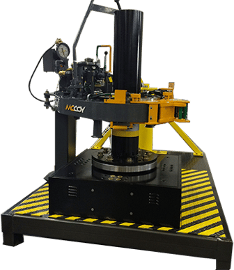
Texas International Oilfield Tools (TIOT) offers a free standing test stand for testing of hydraulic casing and tubing power tongs. The test stand is designed to resist torque applied by a power tong through a test mandrel.
The test stand is an air operated device that utilizes a hydraulic active dual spring disc brake chamber in order to apply friction force (“brake” action) to the rotating (or stationary) test mandrel mechanism. The power tong is tested by applying torque to the test stand’s mandrel. The test stand’s brake is activated by pushing and twisting clockwise the red control box button on the control box. A brake foot pedal is supplied as backup for the mini power unit. Using the control box mounted on the test stand, the black knob regulates pressure.
The terms VARCO, VARCO-BJ, and BJ are trademarks of Varco I/P, Inc., National Oilwell Varco, L.P., or their affiliates. Texas International Oilfield Tools is not an authorized distributor of any Varco I/P or NATIONAL OILWELL VARCO product. Texas International Oilfield Tools is not affiliated with Varco I/P, Inc., National Oilwell Varco, L.P., or their affiliates. Varco I/P, Inc., National Oilwell Varco, L.P., and their affiliates do not endorse any Texas International Oilfield Tools’ products or replacement parts.

When application demand a wide range of sizes, this tong handles pipe sizes 2⅜ inches all the way to 7⅝. The 7⅝ HDS-25 uses a two-speed mechanical shift transmission in conjunction with the two-speed Hydra-Shift® motor, providing the operator a very flexible choice of working torque/RPMs during makeup or breakout. Our patent-pending CASE STIFFENER technology enhances overall torque to provide consistent torque output. Having a high full 360° rotational torque and speed-shifting capability ensures the tong can makeup special torque-turn connections that require continuous rotation. Also, the CASE STIFFENER technology reduces stress and wear on the rotary gear teeth.
7⅝ HDS CHROMEBOSS®: The 7⅝ HDS comes standard with pivot style heads; however, upon ordering can be supplied with slide-heads which is designated as 7⅝ HDS. The 7⅝ HDS is part of our CHROMEBOSS® series of tongs that is suitable for running corrosion-resistant alloy (CRA) tubulars. Two slide heads in the tong provide a consistent radial load on the tubular, reduced tubular deformation, and when combined with our pyramid fine tooth or True-GritTM wrap-around dies provides excellent gripping capabilities on corrosion-resistant alloy (CRA).
The Tri-Grip® Backup is the industry standard for reliable make-up and break-out of tubular connections that are optionally supplied with Eckel tongs. Utilizing two hydraulic cylinders and a three head arrangement ensures a slip-free operation. The backup is suspended at an adjustable level below the power tong employing three hanger legs and allows the backup to remain stationary while the power tong moves vertically to compensate for the connection"s thread travel. The Tri-Grip® uses two pivoting heads and one stationary. The Eckel Tri-Grip® Backup has exceptional gripping capabilities with Rig Dies when running drill pipe or optional Eckel Wrap-Around True-Grit® dies or Pyramid Fine Tooth dies for making up other types of tubular.
Looking for a job? We are hiring! We have a variety of positions open, including Tong Mechanics, CNC Machinist, Fork Lift Driver, Secretarial – Eng. Dept, and Invoicing Clerk. We offer excellent benefits, including 401K Matching, Health Insurance, Life Insurance, and Paid Vacation / Holidays. Apply today by emailing jobs2@eckel.com or apply in person at Eckel Manufacturing Co., Inc., 8035 North County Road West, Odessa, TX.

The Model 300 Sucker Rod Tongs made to make getting on and off the rods easier and to reduce weariness and mishaps. The Model 300 accelerates tripping the pipe, protects rods, and all while simply using the same power unit as a tubing tong. The Model 300 comes with a modifiable relief valve to set the torque; 95 RPM and 850ft/lbs. of torque at high range. Situated by a firm torque arm, this tong can engage automatically and release automatically by a reversing tong.
The Model 300M Sucker Rod Tongs made to make getting on and off the rods easier and to reduce weariness and mishaps. The Model 300 accelerates tripping the pipe, protects rods, and all while simply using the same power unit as a tubing tong. The Model 300 comes with a modifiable relief valve to set the torque; 95 RPM and 850ft/lbs. of torque at high range. Situated by a firm torque arm, this tong can engage automatically and release automatically by a reversing tong. A feature unique to this model is the ability to breakout and make-up 1-1/8” rods without over torqueing.
The Model 500 Power Tubing Tong has a size range of 1-5/16” to 7”, joint make-up in 5 seconds, and joint break-out in 7 seconds. With a split glide ring, both safer and more convenient access to jaws and final drive gear components is attainable, while pressurized oil baths ensure that the Model 500 is properly lubricated. The Model 500 also features an adjustable clutch and air or hydraulic assist for the back-up tool. Also fitted with a “Power Shift” Transmission, the operator is able to adjust gears during operation while the Improved Drive Alignment minimizes wasted power.
The Model 600 Power Tubing Tongs feature an adjustable clutch and is available in either air or hydraulic assist for the back-up tool. Also fitted with a “Power Shift” Transmission, the operator is able to adjust gears during operation while the Improved Drive Alignment minimizes wasted power. The Model 600 permits joint make-up in 5 seconds and joint break-out in 7 seconds. With a split glide ring, both safer and more convenient access to jaws and final drive gear components is attainable, while pressurized oil baths ensure that the Model 500 is properly lubricated.
The Model RSHD Power Tubing Tongs are truly a heavy duty piece of equipment that is for the tough jobs. The Model RSHD has more steel weight and gussets added to the bottom in order to diminish chance of case spreading. This model features a customary chain-driven design, integral sprocket, and outer ring. Lastly, the Model RSHD utilizes a familiar jaw-and-bushing biting system.
The Model 700 features the highest torque of all the Power Tubing/Casing Tongs at 20,000 ft./lbs. at 2000 PSI. This model consists of a light drill pipe, tubing, and casing.
Power tongs are machines that may be used to make-up and break-out threaded connections between adjacent tubular segments by gripping and rotating a first tubular segment relative to a second tubular segment to either make-up or break-out the threaded connection between the two tubular segments. FIG. 1 is a perspective view of an example of an externally gripping power tong 100. The power tong 100 includes a drive motor 110 that may be hydraulically, electrically, and/or pneumatically-powered, and a gripping assembly mechanically coupled to the motor 110 for gripping and rotating a tubular segment received within a bay 106. A generally “C”-shaped gear housing 112 supports a pair of pivoting doors 114. The doors 114 may be closed to secure the bay 106 or swung open (as indicated in FIG. 1) to provide access to the bay 106. The bay 106 is generally surrounded by the gear housing 112. The center of the bay 106 is between a pair of generally opposed pivotable gripping jaws 120, each having a generally arcuate gripping surface disposed radially inwardly toward the center of the bay 119.
Makeup requirements for tubular connections require high torque, such as in the order of thousands, and up to tens of thousands, of ft-lb torque. The components of a power tong must be capable of producing and sustaining the torques required to rotate tubular segments. As such, safely and effectively handling tubular members within an oilfield environment remains a priority to increase the efficiency and effectiveness of such tubular handling equipment.
FIGS. 2A-2C show multiple views of a power tong assembly used to grip and rotate a tubular segment in accordance with one or more embodiments of the present disclosure;
FIGS. 5A and 5B show multiple schematic views of a simplified hydraulic circuit for a power tong assembly in accordance with one or more embodiments of the present disclosure.
In accordance with various aspects disclosed herein, the present disclosure relates to a power tong assembly that may be used to make-up, break-out, and/or torque two or more tubular members, such as within an oilfield exploration and production operation environment discussed above. The power tong assembly includes a power tong is configured to grip and rotate a tubular segment in a first direction, such as to make-up a threaded connection with the tubular segment, and in a second direction, such as to break-out the threaded connection with the tubular segment. The power tong assembly further includes an interlock system operably coupled to the power tong, in which the interlock system may be configured to selectively allow the power tong to rotate the tubular segment in one of the first direction and the second direction while preventing the power tong to rotate the tubular segment in the other of the first direction and the second direction. The interlock system may, additionally or alternatively, be configured to selectively allow the power tong to rotate or not rotate in response to conditions that are sensed by the interlock system.
For example, the power tong may be operated in two directions, such as a make-up direction (e.g., operated in a make-up setting) and a break-out direction (e.g., operated in a break-out setting), in which the make-up setting enables the power tong to rotate a tubular segment in the first direction to make-up a threaded connection with the tubular segment, and the break-out setting enables the power tong to rotate the tubular segment in the second direction to break-out the threaded connection with the tubular segment. Further, the interlock system includes a make-up setting that allows the power tong to rotate the tubular segment in the first direction to make-up the threaded connection with the tubular segment and a break-out setting that allows the power tong to rotate the tubular segment in the second direction to break-out the threaded connection with the tubular segment. As such, the interlock system is configured to prevent the power tong to operate in the make-up setting when the interlock system is in the break-out setting, and further is configured to prevent the power tong to operate in the break-out setting when the interlock system is in the make-up setting.
In one or more embodiments, the power tong may include a high-speed setting to rotate the tubular segment in the first direction and the second direction in a high gear and a low-speed setting to rotate the tubular segment in the first direction and the second direction in a low gear. Accordingly, in one embodiment, the interlock system is configured to allow the power tong to operate in the make-up setting and the high-speed setting only when the interlock system is in the make-up setting, and is configured to allow the power tong to operate in the break-out setting and the high-speed setting only when the interlock system is in the break-out setting. The interlock system may further include a selector mechanism, such as a plug assembly or a three-way valve, which enables the interlock system to move between the make-up setting and the break-out setting. Further, the interlock system may include a power tong gear position sensor. The power tong gear position sensor may be used to sense and determine if the power tong is configured to operate in high gear (e.g., a high-speed setting) or operate in low gear (e.g., a low-speed setting). Accordingly, as discussed more below, the interlock system may use the selector mechanism and/or the power tong gear position sensor to sense the setting or mode of operation of the power tong, in which the interlock system may be configured to selectively allow the power tong to rotate or not rotate in response to conditions that are sensed by the selector mechanism and/or the power tong gear position sensor of the interlock system. Furthermore, the interlock system may be operably coupled to a bi-directional hydraulic motor of the power tong such that the interlock system disables the hydraulic motor to prevent the power tong to rotate the tubular segment in the other of the first direction and the second direction.
In one or more embodiments, the interlock system may include a selector mechanism, in which the selector mechanism may be used as a tong operator interface to switch and move the interlock system between the make-up setting and the break-out setting. In such an embodiment, if the selector mechanism is in the make-up setting (e.g., a make-up position) and the power tong is actuated in the make-up direction, the interlock system may permit the power tong to operate. In particular, the interlock system may permit the power tong to operate in the make-up direction in high-speed (e.g., the high-speed setting) and low-speed (e.g., the low-speed setting) if the selector mechanism of the interlock system is in the make-up position. Further, in such an embodiment, the interlock system may prevent or block the power tong to operate in the break-out direction in high-speed and only permit the power tong to operate in the break-out direction in low-speed if the selector mechanism of the interlock system is in the make-up position.
Further, if the selector mechanism is in the break-out setting (e.g., a break-out position) and the power tong is actuated in the break-out direction, the interlock system may permit the power tong to operate. In particular, the interlock system may permit the power tong to operate in the break-out direction in high-speed and low-speed if the selector mechanism of the interlock system is in the break-out position. Further, in such an embodiment, the interlock system may prevent or block the power tong to operate in the make-up direction in high-speed and only permit the power tong to operate in the make-up direction in low-speed if the selector mechanism of the interlock system is in the break-out position.
Referring now to FIGS. 2A, 2B, and 2C, multiple views of a power tong assembly 200 used to grip and rotate a tubular segment 202 in accordance with one or more embodiments of the present disclosure are shown. In particular, FIG. 2A shows a perspective view of the power tong assembly 200 when in use to make-up and/or break-out a threaded connection between a first upper tubular segment 202A and a second lower tubular segment 202B, FIG. 2B shows an above schematic view of the power tong assembly 200 when in use to make-up a threaded connection with the tubular segment 202, and FIG. 2C shows another above schematic view of the power tong assembly 200 when in use to break-out a threaded connection with the tubular segment 202.
In one or more embodiments, when making-up and breaking-out threaded connections between tubular segments, a mechanism or component is used to hold reaction torque on one tubular segment while the power tong is used to rotate the other tubular segment. One or more power tong assemblies may include with integral backup wrenches, in which the backup wrench may hold reaction torque on a tubular segment while the power tong makes-up and breaks-out threaded connections by rotating an adjacent tubular segment. In an embodiment in which a power tong assembly does not include an integral backup wrench, such as shown in FIG. 2A, reaction torque may be held on the lower tubular segment 202B using a drilling rotary 204 and/or other tubular gripping mechanism (e.g., a manual tong, a spider, a collar load support), while the power tong assembly 200 is used to rotate and apply torque to the upper tubular segment 202A.
As shown in FIGS. 2A-2C, a tong operator 206 may be in close proximity to the power tong assembly 200, such as particularly when making-up and breaking-out connections. For example, a power tong 208 of the power tong assembly 200 includes a make-up setting and a break-out setting, with the power tong 208 switchable between the make-up and break-out settings. In the make-up setting, the power tong 208 is used to rotate the upper tubular segment 202A in the first direction to make-up a threaded connection between the upper tubular segment 202A and the lower tubular segment 202B, and in the break-out setting, the power tong 208 is used to rotate the upper tubular segment 202A in the second direction to break-out the threaded connection between the upper tubular segment 202A and the lower tubular segment 202B. Furthermore, the power tong 208 may include a high-speed setting and a low-speed setting, with the power tong 208 switchable between the high-speed and low-speed settings. In the high-speed setting, the power tong 208 is used to rotate the upper tubular segment 202A in the first direction or in the second direction in a high gear. In the low-speed setting, the power tong 208 is used to rotate the upper tubular segment 202A in the first direction or in the second direction in a low gear. Accordingly, the tong operator 206 may operate and switch the power tong 206 between each of these different settings.
FIG. 2B shows an example of the power tong 208 when in the make-up setting, in which the power tong 208 is used in this embodiment to rotate the tubular segment 202A in a first direction (e.g., clockwise direction) when making-up threaded connections with the tubular segment 202A. As the power tong 208 rotates the tubular segment 202A in the clockwise direction, the power tong 208 will have the tendency to move and rotate from a reactive torque 210A in the counter-clockwise direction. In one or more embodiments, to prevent movement and rotation of the power tong 208, a snub line 212A may be attached to the power tong 208 in a direction opposite to the reactive torque 210A to prevent movement of the power tong 208 in response to the reactive torque 210A. As such, the snub line 212A may be used in the orientation shown to prevent rotation of the power tong 208 when making-up threaded connections with the tubular segment 202A.
Similarly, FIG. 2C shows an example of the power tong 208 when in the break-out setting, in which the power tong 208 is used in this embodiment to rotate the tubular segment 202A in a second direction (e.g., counter-clockwise direction) when breaking-out threaded connections with the tubular segment 202A. As the power tong 208 rotates the tubular segment 202A in the counter-clockwise direction, the power tong 208 will have the tendency to move and rotate from a reactive torque 210B in the clockwise direction as well. In one or more embodiments, to prevent movement and rotation of the power tong 208, a snub line 212B may be attached to the power tong 208 in a direction opposite to the reactive torque 210A. As such, the snub line 212B may be used to prevent rotation of the power tong 208 when breaking-out threaded connections with the tubular segment 202A.
As shown in FIGS. 2B and 2C, the direction of the attachment of the snub line 212 to the power tong 208 depends on if the power tong 208 is in the make-up setting or the break-out setting. However, as the power tong 208 may not include an integral backup wrench, and is shown to only include the rotary 204 to hold reaction torque, the power tong 208 may present a risk to the tong operator 206. In particular, in the embodiment shown in FIG. 2B, if the tong operator 206 switches the power tong 208 to operate in the break-out setting instead of the make-up setting, the snub line 212A will be ineffective in preventing rotation of the power tong 208. This will allow the power tong 208 to rotate and spin around the tubular segment 202A in the clockwise direction and strike the tong operator 206. This inefficiency is even further magnified if the tong operator 206 is operating the power tong 208 in the high-speed setting, as opposed to the low-speed setting. Similarly, in the embodiment shown in FIG. 2C, if the tong operator 206 switches the power tong 208 to operate in the make-up setting instead of the break-out setting, the snub line 212B will be ineffective in preventing rotation of the power tong 208. This will allow the power tong 208 to rotate and spin around the tubular segment 202A in the counter-clockwise direction and strike the tong operator 206.
Though not shown, the tong operator 206 often operates the power tong 208 from scaffolding or within confined spaces, in which the power tong 208 may then knock the tong operator 206 from the scaffolding and/or smash the tong operator 206 against the structure of a drilling rig, both of which are life-threatening injuries to the tong operator 206. Accordingly, the present disclosure relates to a power tong assembly, in which the power tong assembly includes a power tong and includes an interlock system operably coupled to the power tong, in which the interlock system is configured to selectively allow the power tong to rotate the tubular segment in one of the first direction and the second direction while preventing the power tong to rotate the tubular segment in the other of the first direction and the second direction.
As discussed above, the power tong 208 includes a make-up setting and a break-out setting, which may be operated through one or more handles or levers included with the power tong 208. The make-up setting enables the power tong 208 to rotate the tubular segment 202A in the first direction to make-up a threaded connection with the tubular segment 202A, and the break-out setting enables the power tong 208 to rotate the tubular segment 202A in the second direction to break-out the threaded connection with the tubular segment 202A.
Accordingly, an interlock system in accordance with the present disclosure that is operably coupled to the power tong 208 also includes a make-up setting and a break-out setting, in which the interlock system may be operated using a selector mechanism included within the interlock system. The make-up setting of the interlock system allows the power tong 208 to rotate the tubular segment 202A in the first direction, such as in both the high-speed setting and the low-speed setting, to make-up the threaded connection with the tubular segment 202A, and the break-out setting of the interlock system allows the power tong 208 to rotate the tubular segment 202A in the second direction, such as in both the high-speed setting and the low-speed setting, to break-out the threaded connection with the tubular segment 202A. FIG. 3A shows a flow chart of operation of a power tong assembly in accordance with the present disclosure. As shown, the interlock system may be set in either an interlock system make-up setting 302A or an interlock system break-out setting 302B. When in the interlock system make-up setting 302A, the power tong is enabled/allowed to operate in a power tong make-up setting 304A and is disabled/prevented to operate in a power tong break-out setting 304B. When in the interlock system break-out setting 302B, the power tong is disabled/prevented to operate in a power tong make-up setting 304C and is enabled/allowed to operate in a power tong break-out setting 304D.
As such, with reference to FIGS. 2A-2C, the interlock system is configured to prevent the power tong 208 to operate in the make-up setting when the interlock system is in the break-out setting, and further is configured to prevent the power tong 208 to operate in the break-out setting when the interlock system is in the make-up setting. Such a configuration may provide an additional safety feature to the power tong assembly 200, thereby helping prevent the tong operator 206 from unintentionally making-up and/or breaking-out of threaded connections that may lead to accidents within a drilling environment.
Further, as also discussed above, the power tong 208 may include a high-speed setting and a low-speed setting, which may be operated through one or more handles or levers included with the power tong 208. The high-speed setting enables the power tong 208 to rotate the tubular segment 202A in the first direction and/or the second direction in a high gear, and the low-speed setting enables the power tong 208 to rotate the tubular segment 202A in the first direction and/or the second direction in a low gear.
Accordingly, an interlock system in accordance with the present disclosure may be configured to allow the power tong 208 to operate in the make-up setting and the high-speed setting only when the interlock system is in the make-up setting, and may further be configured to allow the power tong 208 to operate in the break-out setting and the high-speed setting only when the interlock system is in the break-out setting.
FIG. 3B shows a flow chart of operation of a power tong assembly with an interlock system in a make-up setting in accordance with the present disclosure. The interlock system may be set in an interlock system make-up setting 306A, and the power tong may be set in either a power tong high-speed setting 308A or a power tong low-speed setting 308B. When in the interlock system make-up setting 306A and the power tong high-speed setting 308A, the power tong is enabled/allowed to operate in a power tong make-up setting 310A and is disabled/prevented to operate in a power tong break-out setting 310B. When in the interlock system make-up setting 306A and the power tong low-speed setting 308B, the power tong is enabled/allowed to operate in a power tong make-up setting 310C and is also enabled/allowed to operate in a power tong break-out setting 310D.
Further, FIG. 3C shows a flow chart of operation of a power tong assembly with an interlock system in a break-out setting in accordance with the present disclosure. The interlock system may be set in an interlock system break-out setting 306B, and the power tong may be set in either a power tong high-speed setting 308C or a power tong low-speed setting 308D. When in the interlock system break-out setting 306B and the power tong high-speed setting 308C, the power tong is disabled/prevented to operate in a power tong make-up setting 310E and is enabled/allowed to operate in a power tong break-out setting 310F. When in the interlock system break-out setting 306B and the power tong low-speed setting 308D, the power tong is enabled/allowed to operate in a power tong make-up setting 310G and is also enabled/allowed to operate in a power tong break-out setting 310H.
FIG. 3D shows a flow chart of operation of a power tong assembly in accordance with the present disclosure. In one or more embodiments, the interlock system may include a selector mechanism 312, in which the selector mechanism 312 may be used as a tong operator interface to switch and move the interlock system between operating the power tong in a make-up direction 314 or a break-out direction 316. Further, the interlock system may include a power tong gear position sensor 318. The power tong gear position sensor 318 may be used to sense and determine if the power tong is configured to operate in high gear (e.g., a high-speed setting) or operate in low gear (e.g., a low-speed setting). If the selector mechanism 312 is in the make-up setting (e.g., a make-up position) and the power tong gear sensor 318 detects that the power tong is in high gear, the interlock system may permit the power tong to operate in the make-up direction in high gear 320A and prevent or block the power tong to operate in the break-out direction in high gear 320B. If the selector mechanism 312 is in the make-up setting and the power tong gear sensor 318 detects that the power tong is in low gear, the interlock system may permit the power tong to operate in the make-up direction in low gear 320C and permit the power tong to operate in the break-out direction in high gear 320D.
Further, If the selector mechanism 312 is in the break-out setting (e.g., a break-out position) and the power tong gear sensor 318 detects that the power tong is in high gear, the interlock system may prevent or block the power tong to operate in the make-up direction in high gear 320E and permit the power tong to operate in the break-out direction in high gear 320F. If the selector mechanism 312 is in the break-out setting and the power tong gear sensor 318 detects that the power tong is in low gear, the interlock system may permit the power tong to operate in the make-up direction in low gear 320G and permit the power tong to operate in the break-out direction in high gear 320H.
An interlock system in accordance with the present disclosure may have one or more different types of configurations. For example, as shown and discussed below, the interlock system may be hydraulically controlled, in which the interlock system may include one or more hydraulic components and/or actuators and may be used to selectively control hydraulic fluid flow through the power tong. In particular, the interlock system may be used to selectively provide and control a supply of hydraulic fluid to a hydraulic motor of the power tong. However, in another embodiment, the interlock system may additionally or alternatively be magnetically controlled, electrically controlled, mechanically controlled, and/or pneumatically controlled. Accordingly, the present disclosure contemplates other methods and configurations for an interlock system than only those discussed herein, and therefore the present disclosure should not be so limited.
Referring now to FIGS. 4A-4G, multiple views of a power tong assembly 400 in accordance with one or more embodiments of the present disclosure are shown. The power tong assembly 400 includes a power tong 402 used for gripping and rotating tubular segments, particularly for making-up and breaking-out threaded connections, and also includes an interlock system 410. The interlock system 410 is operably coupled to the power tong 402 to selectively allow the power tong to rotate the tubular segment in one of the make-up and the break-out direction while also preventing the power tong 402 from rotating the tubular segment in the other of the make-up and the break-out direction. Accordingly, in this embodiment, the interlock system 410, or at least portions or components thereof, are positioned upon and operably coupled to a motor 404 of the power tong 402. The motor 404 may be a bi-directional hydraulic motor, in which the interlock system 410 may be used to disable the motor 404, such as by limiting hydraulic fluid supply to the motor 404, to prevent the power tong 402 from rotating the tubular segment in an undesired direction or at an undesired speed.
Along with the motor 404, the power tong 402 may include one or more handles 406 to set the power tong 402 in the make-up setting or the break-out setting. For example, in FIG. 4A, one of the handles 406 may be moved to set the power tong 402 in either the make-up setting or the break-out setting, while the other of the handles 406 may be moved to operate a lift cylinder operably coupled to the power tong 402 to selectively raise and lower the power tong 402. The power tong 402 may further include a handle 408 (e.g., speed shifting shaft) to set the power tong 402 in the high-speed setting or the low-speed setting. For example, in FIG. 4A, the handle 408 may be moved in one direction to set the power tong 402 in the high-speed setting or may be moved in another direction to set the power tong 402 in the low-speed setting.
As the interlock system 410 may include multiple portions or components, the interlock system 410 is shown in this embodiment as including a manifold 412, which may be formed as one or more housings, and a speed detection mechanism 414 (e.g., power tong gear position sensor 318). FIG. 4B shows a detailed view of the manifold 412, and FIG. 4C shows a detailed view of the speed detection mechanism 414. The manifold 412 may be positioned on the motor 404 of the power tong 402 and may have hydraulic fluid pumped through the manifold 412. As such, the manifold 412 may include hydraulic logic elements to selectively divert hydraulic fluid flow therethrough, such as including one or more valves, plugs, and/or switches to selectively divert the flow through the manifold 412. In particular, in this embodiment, the manifold 412 may include therewith or therein a selector mechanism 416, a check valve, an orifice or a needle valve, and an unloader valve.
The selector mechanism 416 may be included within the interlock system 410, and may be used as a tong operator interface to switch and move the interlock system 410 between the make-up setting and the break-out setting. Examples of the selector mechanism 416 are shown in FIGS. 4D-4F. In FIGS. 4D and 4E, the selector mechanism 416 is shown as a plug assembly 418 that includes one or more plugs. The plugs of the plug assembly 418 may be rearranged and positioned within the manifold 412 to set the interlock system 410 in a make-up setting (e.g., high-speed make-up setting), as shown in FIG. 4D, or to set the interlock system 410 in a break-out setting (e.g., high-speed break-out setting), as shown in FIG. 4E. Alternatively, the selector mechanism 416 is shown as a three-way valve 420 in FIG. 4F, such as a three-way ball valve, in which the three-way valve 420 may be set and moved between the make-up setting and the break-out setting.
The speed detection mechanism 414 may be operably coupled to the handle 408 that shifts the power tong 402 between the high-speed setting and the low-speed setting. Accordingly, the speed detection mechanism 414 may be positioned adjacent the handle 408, such as positioned on the bottom of the power tong 402. In this embodiment, the speed detection mechanism 414 may include a cam-operated valve 422. FIG. 4G shows a cross-sectional view of the cam-operated valve 422. As such, the cam-operated valve 422 is activated and moved between an open position and a closed position based on movement of a camming rod 424. The camming rod 424 may be coupled to the handle 408, and therefore the camming rod 424 may move with the handle 408 when shifting the power tong 402 between the high-speed setting and the low-speed setting. Accordingly, the cam-operated valve 422 may detect the speed of the power tong 402, such as if the power tong 402 is in the high-speed setting or the low-speed setting, based upon the position and movement of the camming rod 424.
Referring now to FIGS. 5A and 5B, multiple schematic views of a simplified hydraulic circuit 500 for a power tong assembly in accordance with one or more embodiments of the present disclosure are shown. As shown in this embodiment, the hydraulic circuit 500 includes a hydraulic motor 502 (e.g., bi-directional hydraulic motor), such as the motor 404 shown in FIG. 4A, and a directional control valve 504 (e.g., four-way, three-position directional control valve) that controls fluid flow to the hydraulic motor 502. The directional control valve 504 may include or be operably coupled to the handles 406 of the power tong 402. As such, the directional control valve 504 may be used to control the direction of rotation of the hydraulic motor 502, and therefore may be used to move the power tong 402 between the make-up setting and the break-out setting. Hydraulic fluid may be provided along a pressure flow path 550 and flow through a motor inlet flow path 552 into the directional control valve 504. The directional control valve 504 may then be used to selectively flow the hydraulic fluid into either the A-side or the B-side of the hydraulic motor 502, depending on the desired rotation of the power tong 402. Hydraulic fluid may then return from the hydraulic motor 502 back into the directional control valve 504, in which hydraulic fluid may then be provided to a return flow path 556 through a motor outlet flow path 554.
The directional control valve 560, as shown in the embodiment in FIGS. 5A and 5B, may be opened from operation of either a directional control valve 564 or a directional control valve 566 fluidly coupled in parallel to the directional control valve 560 along the case drain flow path 562. The directional control valve 564 (e.g., two-way, two-position directional control valve) may include an interlock valve that is movable between the open and closed position based upon an open or closed position of a door of the power tong 402. If the door of the power tong 402 is opened, the directional control valve 564 may relieve pilot pressure to the directional control valve 560 along the case drain flow path 562, thereby opening the directional control valve 560 and preventing operation of the hydraulic motor 502.
The hydraulic circuit 500 may further include a directional control valve 576 (e.g., three-way, two-position directional control valve), which may be the cam-operated valve 422 of the speed detection mechanism 414 shown in FIGS. 4A, 4C, and 4G. The directional control valve 576 may be movable between the open and closed position based upon if the power tong 402 is in the high-speed setting and the low-speed setting. As such, in this embodiment, the directional control valve 576 may be in the open position when the power tong 402 is in the high-speed setting, thereby fluidly coupling the pilot flow path 574 to the pilot flow path 568. Further, as shown in FIGS. 5A and 5B, the directional control valve 576 may be in the closed position when the power tong 402 is in the low-speed setting, thereby preventing fluid from flowing from the pilot flow path 574 to the pilot flow path 568. Furthermore, the hydraulic circuit 500 may include a check valve 578 and an orifice or a needle valve 580. The check valve 578 and the needle valve 580 may be in parallel with each other, as shown, and may be fluidly coupled to the pilot flow path 574 or the pilot flow path 568.
In operation, the selector mechanism 570 may be used to either allow fluid flow through the A-side motor flow path 572A or the B-side motor flow path 572B and into the pilot flow path 574. When the A-side motor flow path 572A is open with fluid allowed to flow therethrough, the A-side of the hydraulic motor 502 is not operational. For example, hydraulic fluid may be provided along the motor inlet flow path 552, into the directional control valve 504, and towards the A-side of the hydraulic motor 502. As the A-side motor flow path 572A is open, hydraulic fluid will flow into the A-side motor flow path 572A and continue along the pilot flow path 574. If the directional control valve 576 is present and open (e.g., the power tong 402 is in the high-speed setting), hydraulic fluid may flow from the pilot flow path 574 to the pilot flow path 568 to provide pilot pressure to the directional control valve 566. When pilot pressure is received along the pilot flow path 568 to the directional control valve 566, the directional control valve 566 will open, thereby relieving pilot pressure to the directional control valve 560 along the case drain flow path 562, opening the directional control valve 560, and preventing operation of the hydraulic motor 502.
In an embodiment in which hydraulic fluid received through the A-side of the hydraulic motor 502 causes the power tong 402 to make-up threaded connections with a tubular segment, the right side of the directional control valve 504 may be used as the make-up setting for the power tong 402, and the opening the B-side motor flow path 572B may be used as the make-up setting for the selector mechanism 570 (e.g., selector mechanism 416). In such an embodiment, the hydraulic motor 570 may, thus, be disabled when the directional control valve 504 is switched to the left side for the break-out setting of the power tong 402, thereby disabling and preventing the hydraulic motor 570, and the power tong 402, from operating in the break-out setting when the interlock system 410 is in the make-up setting.
Similarly, in an embodiment in which hydraulic fluid received through the B-side of the hydraulic motor 502 causes the power tong 402 to break-out threaded connections with a tubular segment, the left side of the directional control valve 504 may be used as the break-out setting for the power tong 402, and the opening the A-side motor flow path 572A may be used as the break-out setting for the selector mechanism 570 (e.g., selector mechanism 416). In such an embodiment, the hydraulic motor 570 may, thus, be disabled when the directional control valve 504 is switched to the right side for the make-up setting of the power tong 402, thereby disabling and preventing the hydraulic motor 570, and the power tong 402, from operating in the make-up setting when the interlock system 410 is in the break-out setting.
Further, as discussed above, the directional control valve 566 (e.g., unloader valve) may be used as a disabling portion within the interlock system to disable and prevent rotation of the power tong based a speed detection portion (e.g., a directional control valve 576 and/or a cam-operated valve 422) and the direction detection portion (e.g., selector mechanism 570). For example, when pilot pressure is received along the pilot flow path 568 to the directional control valve 566, the directional control valve 566 will open, thereby relieving pilot pressure to the directional control valve 560 along the case drain flow path 562. This enables the directional control valve 560 to open, in which hydraulic fluid then flows along the bypass flow path 558 instead of the motor inlet flow path 552, thereby disabling and preventing the hydraulic motor 502 from operation.
Accordingly, a power tong assembly including a power tong and an interlock system in accordance with the present disclosure may include one or more advantages, such as by decreasing the likelihood of an accident when operating a power tong. In particular, the interlock system is configured to selectively allow the power tong to rotate the tubular segment in one of the first direction and the second direction while preventing the power tong to rotate the tubular segment in the other of the first direction and the second direction. As such, the interlock system may be used to prevent the power tong from operating in a direction unintended by a tong operator, thereby preventing damage to the power tong, to the tubular segments handled by the power tong, and the tong operator.


 8613371530291