
power tong snub line quotation
The tong should be secured for both make-up or break-out operation, by utilizing the snub line. If this is not done, the tong may be thrown against operator causing physical harm.
When using the mechanical shift lever to change speeds, the power tong must first come to a complete stop before shifting. When using tongs hydraulic shift two-speed motor to change speeds, the tong may be shifted "On the Run."
Eckel tongs have proven to basically to last forever with minimal maintenance as all they are manufactured with the highest quality of steel. Using Eckel equipment tells your customer that you have the highest quality equipment on the market.
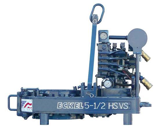
Tong size is determined by range of tubulars you will run. For example a 5-1/2 Hydra-Shift® is capable of running tubulars 5-1/2-inches and smaller while the 14 UHT is capable of running tubulars 14-inches and smaller. It is important not to use a large range of sizes with just one tong. If you have a 10-3/4 Standard and you regularly run 4-1/2-inch tubing with this tong, you might consider using a smaller tong.
PSI pressure determines the maximum torque the tong will safely be able to reach. Eckel rates all their tongs at the industry standard 2500 PSI. A competitor with a similar size tong may show more or the same torque as an Eckel tong due to a higher PSI from the power unit (which is in fine print) in an effort to fool you, thinking there tong is equal to the industry standard (Eckel tong.)
Gallons Per Minute determines the rotational speed of the tong. A low GPM will cause the tong to operate at a lower speed while a high GPM will result in the tong to rotate at a higher speed. Eckel offers an RPM (Revolutions per minute) Control which is a flow divider to decrease the amount of hydraulic fluid that reaches the tong if needed, the remaining fluid is returned to the power unit reservoir. By decreasing the amount of fluid reaching the tong the operator is able to control the maximum RPM of the tong.
Field tests have shown depending on several factors most power units used in above 32 degrees Fahrenheit conditions no matter if your hydraulic oil tank holds 200 gallons of oil, will exceed 150 degrees during a short 8 hour job. Most power units without hydraulic oil coolers exceed 170 degrees which is way past the recommended guide lines.

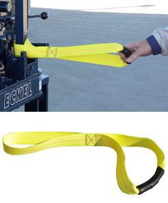
Eckel offers a broad range of accessories to compliment our power tongs. From torque control systems and gauges to case handles and tong straps, Eckel has the right accessory option for your specific application.
Eckel offers torque control systems to monitor the torque turn values when making up tubular connections with the system automatically stopping tong operation once reaching a specific torque. Any flaws in the make-up process will be readily shown in a graph.
The Door Interlock is offered as an optional safety feature for use with the power tong to prevent accidental operation of the power tong when the door is open. The door interlock prevents tong operation whenever the tong door is open by impeding hydraulic fluid to the tong motor.
A hydraulic Tri-Grip® or Cam Backup tool is optionally supplied with Eckel tongs. In operation this tool provides a backup when in break-out or make-up situations. This hydraulically operated backup tool, uses hydraulic cylinders and a head arrangement to insure slip-free operation.
A standard feature on many of our tongs. Dies have evolved since tongs became commonplace in the oilfields. Eckel has been at the forefront of this developing technology with the development of larger wrap-around type dies for many of its tong models. We offer coarse tooth design for normal carbon steel pipe and collars and fine tooth for special alloys such as 9, 13, 23, 25 chrome and fiberglass to greatly minimize markings on the tubulars.
Designed for improved safety when handling the tong. Up to four Case Handles can be optionally mounted on most tong models. Large top and bottom caps help protect the operator when maneuvering the tong on and off the tubulars.
Eckel continues to set industry safety standards with the optional Finger Guard Option. This shield covers the gap between the tong door and tong body, without limiting door operation. Door will open and close freely.
Industrial strength straps feature a rubber gripping surface to allow for easily pulling the tong on and off the tubular. These optional straps are mounted on the tong door and on both sides of the solid hanger area of the tong using a Lark"s Head Knot.
The adjustable motor port relief valve is used to control or limit the hydraulic pressure to the tong motor thus controlling the maximum torque output of the power tong. The valve controls only the hydraulic pressure to the tong motor leaving full system pressure available for other functions such as lift cylinder and hydraulic backup.
RPM Control: The RPM Control is a flow divider that decreases the amount of hydraulic fluid that reaches the tong, the remaining fluid is returned to the reservoir. By decreasing the amount of fluid reaching the tong the operator is able to control the maximum RPM"s the tong will deliver.
Tongs equipped with the optional Swivel Joints have improved hose life by absorbing system shock when pressured up and preventing twisting, kinking of the hydraulic hoses. In addition tongs are maneuvered more freely on the rig floor on and off the tubular.
The optional torque gauge assembly is used to measure the torque exerted in make-up or break-out operations. Consisting of a hydraulic cylinder and torque gauge connected together by a pressure hose, the torque gauge assembly senses and indicates the torque developed during an operation. For operation, the hydraulic cylinder is connected by a shackle to the rear of the tong; and a snub line is connected to the cylinder. The snub line is tied off to a solid part of the rig structure to form an angle of 90� in order for the gauge to indicate accurate torque readings.
This cylinder provides a means for raising and lowering the tong during operations and is recommended with tongs that have a hydraulic backup due to the extra weight of the tong. The lift cylinder maximum of travel varies depending on tong size.
The optional spring hanger is designed to permit the tong to move up or down to allow for thread length in make-up and break-out operations. When used, the spring hanger should be attached directly to the tong bridle ring and used as a hanger for the tong.
This website is using a security service to protect itself from online attacks. The action you just performed triggered the security solution. There are several actions that could trigger this block including submitting a certain word or phrase, a SQL command or malformed data.
Wire rope, one end of which is fastened to the end of a pipe tong handle attachment point and the other end secured to hold the tong stationary while the tong is in use.

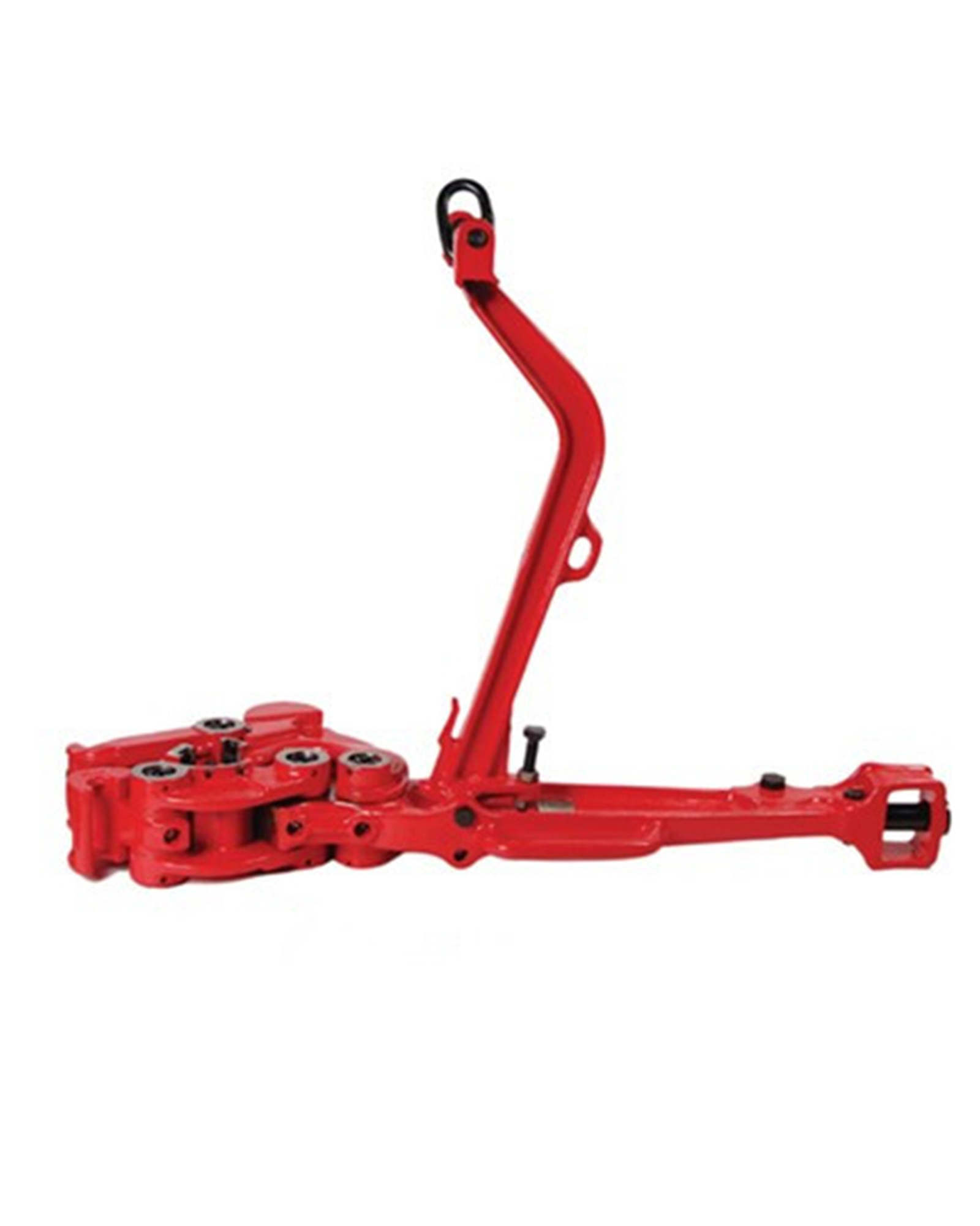
Power tongs are machines that may be used to make-up and break-out threaded connections between adjacent tubular segments by gripping and rotating a first tubular segment relative to a second tubular segment to either make-up or break-out the threaded connection between the two tubular segments. FIG. 1 is a perspective view of an example of an externally gripping power tong 100. The power tong 100 includes a drive motor 110 that may be hydraulically, electrically, and/or pneumatically-powered, and a gripping assembly mechanically coupled to the motor 110 for gripping and rotating a tubular segment received within a bay 106. A generally “C”-shaped gear housing 112 supports a pair of pivoting doors 114. The doors 114 may be closed to secure the bay 106 or swung open (as indicated in FIG. 1) to provide access to the bay 106. The bay 106 is generally surrounded by the gear housing 112. The center of the bay 106 is between a pair of generally opposed pivotable gripping jaws 120, each having a generally arcuate gripping surface disposed radially inwardly toward the center of the bay 119.
Makeup requirements for tubular connections require high torque, such as in the order of thousands, and up to tens of thousands, of ft-lb torque. The components of a power tong must be capable of producing and sustaining the torques required to rotate tubular segments. As such, safely and effectively handling tubular members within an oilfield environment remains a priority to increase the efficiency and effectiveness of such tubular handling equipment.
FIGS. 2A-2C show multiple views of a power tong assembly used to grip and rotate a tubular segment in accordance with one or more embodiments of the present disclosure;
FIGS. 5A and 5B show multiple schematic views of a simplified hydraulic circuit for a power tong assembly in accordance with one or more embodiments of the present disclosure.
In accordance with various aspects disclosed herein, the present disclosure relates to a power tong assembly that may be used to make-up, break-out, and/or torque two or more tubular members, such as within an oilfield exploration and production operation environment discussed above. The power tong assembly includes a power tong is configured to grip and rotate a tubular segment in a first direction, such as to make-up a threaded connection with the tubular segment, and in a second direction, such as to break-out the threaded connection with the tubular segment. The power tong assembly further includes an interlock system operably coupled to the power tong, in which the interlock system may be configured to selectively allow the power tong to rotate the tubular segment in one of the first direction and the second direction while preventing the power tong to rotate the tubular segment in the other of the first direction and the second direction. The interlock system may, additionally or alternatively, be configured to selectively allow the power tong to rotate or not rotate in response to conditions that are sensed by the interlock system.
For example, the power tong may be operated in two directions, such as a make-up direction (e.g., operated in a make-up setting) and a break-out direction (e.g., operated in a break-out setting), in which the make-up setting enables the power tong to rotate a tubular segment in the first direction to make-up a threaded connection with the tubular segment, and the break-out setting enables the power tong to rotate the tubular segment in the second direction to break-out the threaded connection with the tubular segment. Further, the interlock system includes a make-up setting that allows the power tong to rotate the tubular segment in the first direction to make-up the threaded connection with the tubular segment and a break-out setting that allows the power tong to rotate the tubular segment in the second direction to break-out the threaded connection with the tubular segment. As such, the interlock system is configured to prevent the power tong to operate in the make-up setting when the interlock system is in the break-out setting, and further is configured to prevent the power tong to operate in the break-out setting when the interlock system is in the make-up setting.
In one or more embodiments, the power tong may include a high-speed setting to rotate the tubular segment in the first direction and the second direction in a high gear and a low-speed setting to rotate the tubular segment in the first direction and the second direction in a low gear. Accordingly, in one embodiment, the interlock system is configured to allow the power tong to operate in the make-up setting and the high-speed setting only when the interlock system is in the make-up setting, and is configured to allow the power tong to operate in the break-out setting and the high-speed setting only when the interlock system is in the break-out setting. The interlock system may further include a selector mechanism, such as a plug assembly or a three-way valve, which enables the interlock system to move between the make-up setting and the break-out setting. Further, the interlock system may include a power tong gear position sensor. The power tong gear position sensor may be used to sense and determine if the power tong is configured to operate in high gear (e.g., a high-speed setting) or operate in low gear (e.g., a low-speed setting). Accordingly, as discussed more below, the interlock system may use the selector mechanism and/or the power tong gear position sensor to sense the setting or mode of operation of the power tong, in which the interlock system may be configured to selectively allow the power tong to rotate or not rotate in response to conditions that are sensed by the selector mechanism and/or the power tong gear position sensor of the interlock system. Furthermore, the interlock system may be operably coupled to a bi-directional hydraulic motor of the power tong such that the interlock system disables the hydraulic motor to prevent the power tong to rotate the tubular segment in the other of the first direction and the second direction.
In one or more embodiments, the interlock system may include a selector mechanism, in which the selector mechanism may be used as a tong operator interface to switch and move the interlock system between the make-up setting and the break-out setting. In such an embodiment, if the selector mechanism is in the make-up setting (e.g., a make-up position) and the power tong is actuated in the make-up direction, the interlock system may permit the power tong to operate. In particular, the interlock system may permit the power tong to operate in the make-up direction in high-speed (e.g., the high-speed setting) and low-speed (e.g., the low-speed setting) if the selector mechanism of the interlock system is in the make-up position. Further, in such an embodiment, the interlock system may prevent or block the power tong to operate in the break-out direction in high-speed and only permit the power tong to operate in the break-out direction in low-speed if the selector mechanism of the interlock system is in the make-up position.
Further, if the selector mechanism is in the break-out setting (e.g., a break-out position) and the power tong is actuated in the break-out direction, the interlock system may permit the power tong to operate. In particular, the interlock system may permit the power tong to operate in the break-out direction in high-speed and low-speed if the selector mechanism of the interlock system is in the break-out position. Further, in such an embodiment, the interlock system may prevent or block the power tong to operate in the make-up direction in high-speed and only permit the power tong to operate in the make-up direction in low-speed if the selector mechanism of the interlock system is in the break-out position.
Referring now to FIGS. 2A, 2B, and 2C, multiple views of a power tong assembly 200 used to grip and rotate a tubular segment 202 in accordance with one or more embodiments of the present disclosure are shown. In particular, FIG. 2A shows a perspective view of the power tong assembly 200 when in use to make-up and/or break-out a threaded connection between a first upper tubular segment 202A and a second lower tubular segment 202B, FIG. 2B shows an above schematic view of the power tong assembly 200 when in use to make-up a threaded connection with the tubular segment 202, and FIG. 2C shows another above schematic view of the power tong assembly 200 when in use to break-out a threaded connection with the tubular segment 202.
In one or more embodiments, when making-up and breaking-out threaded connections between tubular segments, a mechanism or component is used to hold reaction torque on one tubular segment while the power tong is used to rotate the other tubular segment. One or more power tong assemblies may include with integral backup wrenches, in which the backup wrench may hold reaction torque on a tubular segment while the power tong makes-up and breaks-out threaded connections by rotating an adjacent tubular segment. In an embodiment in which a power tong assembly does not include an integral backup wrench, such as shown in FIG. 2A, reaction torque may be held on the lower tubular segment 202B using a drilling rotary 204 and/or other tubular gripping mechanism (e.g., a manual tong, a spider, a collar load support), while the power tong assembly 200 is used to rotate and apply torque to the upper tubular segment 202A.
As shown in FIGS. 2A-2C, a tong operator 206 may be in close proximity to the power tong assembly 200, such as particularly when making-up and breaking-out connections. For example, a power tong 208 of the power tong assembly 200 includes a make-up setting and a break-out setting, with the power tong 208 switchable between the make-up and break-out settings. In the make-up setting, the power tong 208 is used to rotate the upper tubular segment 202A in the first direction to make-up a threaded connection between the upper tubular segment 202A and the lower tubular segment 202B, and in the break-out setting, the power tong 208 is used to rotate the upper tubular segment 202A in the second direction to break-out the threaded connection between the upper tubular segment 202A and the lower tubular segment 202B. Furthermore, the power tong 208 may include a high-speed setting and a low-speed setting, with the power tong 208 switchable between the high-speed and low-speed settings. In the high-speed setting, the power tong 208 is used to rotate the upper tubular segment 202A in the first direction or in the second direction in a high gear. In the low-speed setting, the power tong 208 is used to rotate the upper tubular segment 202A in the first direction or in the second direction in a low gear. Accordingly, the tong operator 206 may operate and switch the power tong 206 between each of these different settings.
FIG. 2B shows an example of the power tong 208 when in the make-up setting, in which the power tong 208 is used in this embodiment to rotate the tubular segment 202A in a first direction (e.g., clockwise direction) when making-up threaded connections with the tubular segment 202A. As the power tong 208 rotates the tubular segment 202A in the clockwise direction, the power tong 208 will have the tendency to move and rotate from a reactive torque 210A in the counter-clockwise direction. In one or more embodiments, to prevent movement and rotation of the power tong 208, a snub line 212A may be attached to the power tong 208 in a direction opposite to the reactive torque 210A to prevent movement of the power tong 208 in response to the reactive torque 210A. As such, the snub line 212A may be used in the orientation shown to prevent rotation of the power tong 208 when making-up threaded connections with the tubular segment 202A.
Similarly, FIG. 2C shows an example of the power tong 208 when in the break-out setting, in which the power tong 208 is used in this embodiment to rotate the tubular segment 202A in a second direction (e.g., counter-clockwise direction) when breaking-out threaded connections with the tubular segment 202A. As the power tong 208 rotates the tubular segment 202A in the counter-clockwise direction, the power tong 208 will have the tendency to move and rotate from a reactive torque 210B in the clockwise direction as well. In one or more embodiments, to prevent movement and rotation of the power tong 208, a snub line 212B may be attached to the power tong 208 in a direction opposite to the reactive torque 210A. As such, the snub line 212B may be used to prevent rotation of the power tong 208 when breaking-out threaded connections with the tubular segment 202A.
As shown in FIGS. 2B and 2C, the direction of the attachment of the snub line 212 to the power tong 208 depends on if the power tong 208 is in the make-up setting or the break-out setting. However, as the power tong 208 may not include an integral backup wrench, and is shown to only include the rotary 204 to hold reaction torque, the power tong 208 may present a risk to the tong operator 206. In particular, in the embodiment shown in FIG. 2B, if the tong operator 206 switches the power tong 208 to operate in the break-out setting instead of the make-up setting, the snub line 212A will be ineffective in preventing rotation of the power tong 208. This will allow the power tong 208 to rotate and spin around the tubular segment 202A in the clockwise direction and strike the tong operator 206. This inefficiency is even further magnified if the tong operator 206 is operating the power tong 208 in the high-speed setting, as opposed to the low-speed setting. Similarly, in the embodiment shown in FIG. 2C, if the tong operator 206 switches the power tong 208 to operate in the make-up setting instead of the break-out setting, the snub line 212B will be ineffective in preventing rotation of the power tong 208. This will allow the power tong 208 to rotate and spin around the tubular segment 202A in the counter-clockwise direction and strike the tong operator 206.
Though not shown, the tong operator 206 often operates the power tong 208 from scaffolding or within confined spaces, in which the power tong 208 may then knock the tong operator 206 from the scaffolding and/or smash the tong operator 206 against the structure of a drilling rig, both of which are life-threatening injuries to the tong operator 206. Accordingly, the present disclosure relates to a power tong assembly, in which the power tong assembly includes a power tong and includes an interlock system operably coupled to the power tong, in which the interlock system is configured to selectively allow the power tong to rotate the tubular segment in one of the first direction and the second direction while preventing the power tong to rotate the tubular segment in the other of the first direction and the second direction.
As discussed above, the power tong 208 includes a make-up setting and a break-out setting, which may be operated through one or more handles or levers included with the power tong 208. The make-up setting enables the power tong 208 to rotate the tubular segment 202A in the first direction to make-up a threaded connection with the tubular segment 202A, and the break-out setting enables the power tong 208 to rotate the tubular segment 202A in the second direction to break-out the threaded connection with the tubular segment 202A.
Accordingly, an interlock system in accordance with the present disclosure that is operably coupled to the power tong 208 also includes a make-up setting and a break-out setting, in which the interlock system may be operated using a selector mechanism included within the interlock system. The make-up setting of the interlock system allows the power tong 208 to rotate the tubular segment 202A in the first direction, such as in both the high-speed setting and the low-speed setting, to make-up the threaded connection with the tubular segment 202A, and the break-out setting of the interlock system allows the power tong 208 to rotate the tubular segment 202A in the second direction, such as in both the high-speed setting and the low-speed setting, to break-out the threaded connection with the tubular segment 202A. FIG. 3A shows a flow chart of operation of a power tong assembly in accordance with the present disclosure. As shown, the interlock system may be set in either an interlock system make-up setting 302A or an interlock system break-out setting 302B. When in the interlock system make-up setting 302A, the power tong is enabled/allowed to operate in a power tong make-up setting 304A and is disabled/prevented to operate in a power tong break-out setting 304B. When in the interlock system break-out setting 302B, the power tong is disabled/prevented to operate in a power tong make-up setting 304C and is enabled/allowed to operate in a power tong break-out setting 304D.
As such, with reference to FIGS. 2A-2C, the interlock system is configured to prevent the power tong 208 to operate in the make-up setting when the interlock system is in the break-out setting, and further is configured to prevent the power tong 208 to operate in the break-out setting when the interlock system is in the make-up setting. Such a configuration may provide an additional safety feature to the power tong assembly 200, thereby helping prevent the tong operator 206 from unintentionally making-up and/or breaking-out of threaded connections that may lead to accidents within a drilling environment.
Further, as also discussed above, the power tong 208 may include a high-speed setting and a low-speed setting, which may be operated through one or more handles or levers included with the power tong 208. The high-speed setting enables the power tong 208 to rotate the tubular segment 202A in the first direction and/or the second direction in a high gear, and the low-speed setting enables the power tong 208 to rotate the tubular segment 202A in the first direction and/or the second direction in a low gear.
Accordingly, an interlock system in accordance with the present disclosure may be configured to allow the power tong 208 to operate in the make-up setting and the high-speed setting only when the interlock system is in the make-up setting, and may further be configured to allow the power tong 208 to operate in the break-out setting and the high-speed setting only when the interlock system is in the break-out setting.
FIG. 3B shows a flow chart of operation of a power tong assembly with an interlock system in a make-up setting in accordance with the present disclosure. The interlock system may be set in an interlock system make-up setting 306A, and the power tong may be set in either a power tong high-speed setting 308A or a power tong low-speed setting 308B. When in the interlock system make-up setting 306A and the power tong high-speed setting 308A, the power tong is enabled/allowed to operate in a power tong make-up setting 310A and is disabled/prevented to operate in a power tong break-out setting 310B. When in the interlock system make-up setting 306A and the power tong low-speed setting 308B, the power tong is enabled/allowed to operate in a power tong make-up setting 310C and is also enabled/allowed to operate in a power tong break-out setting 310D.
Further, FIG. 3C shows a flow chart of operation of a power tong assembly with an interlock system in a break-out setting in accordance with the present disclosure. The interlock system may be set in an interlock system break-out setting 306B, and the power tong may be set in either a power tong high-speed setting 308C or a power tong low-speed setting 308D. When in the interlock system break-out setting 306B and the power tong high-speed setting 308C, the power tong is disabled/prevented to operate in a power tong make-up setting 310E and is enabled/allowed to operate in a power tong break-out setting 310F. When in the interlock system break-out setting 306B and the power tong low-speed setting 308D, the power tong is enabled/allowed to operate in a power tong make-up setting 310G and is also enabled/allowed to operate in a power tong break-out setting 310H.
FIG. 3D shows a flow chart of operation of a power tong assembly in accordance with the present disclosure. In one or more embodiments, the interlock system may include a selector mechanism 312, in which the selector mechanism 312 may be used as a tong operator interface to switch and move the interlock system between operating the power tong in a make-up direction 314 or a break-out direction 316. Further, the interlock system may include a power tong gear position sensor 318. The power tong gear position sensor 318 may be used to sense and determine if the power tong is configured to operate in high gear (e.g., a high-speed setting) or operate in low gear (e.g., a low-speed setting). If the selector mechanism 312 is in the make-up setting (e.g., a make-up position) and the power tong gear sensor 318 detects that the power tong is in high gear, the interlock system may permit the power tong to operate in the make-up direction in high gear 320A and prevent or block the power tong to operate in the break-out direction in high gear 320B. If the selector mechanism 312 is in the make-up setting and the power tong gear sensor 318 detects that the power tong is in low gear, the interlock system may permit the power tong to operate in the make-up direction in low gear 320C and permit the power tong to operate in the break-out direction in high gear 320D.
Further, If the selector mechanism 312 is in the break-out setting (e.g., a break-out position) and the power tong gear sensor 318 detects that the power tong is in high gear, the interlock system may prevent or block the power tong to operate in the make-up direction in high gear 320E and permit the power tong to operate in the break-out direction in high gear 320F. If the selector mechanism 312 is in the break-out setting and the power tong gear sensor 318 detects that the power tong is in low gear, the interlock system may permit the power tong to operate in the make-up direction in low gear 320G and permit the power tong to operate in the break-out direction in high gear 320H.
An interlock system in accordance with the present disclosure may have one or more different types of configurations. For example, as shown and discussed below, the interlock system may be hydraulically controlled, in which the interlock system may include one or more hydraulic components and/or actuators and may be used to selectively control hydraulic fluid flow through the power tong. In particular, the interlock system may be used to selectively provide and control a supply of hydraulic fluid to a hydraulic motor of the power tong. However, in another embodiment, the interlock system may additionally or alternatively be magnetically controlled, electrically controlled, mechanically controlled, and/or pneumatically controlled. Accordingly, the present disclosure contemplates other methods and configurations for an interlock system than only those discussed herein, and therefore the present disclosure should not be so limited.
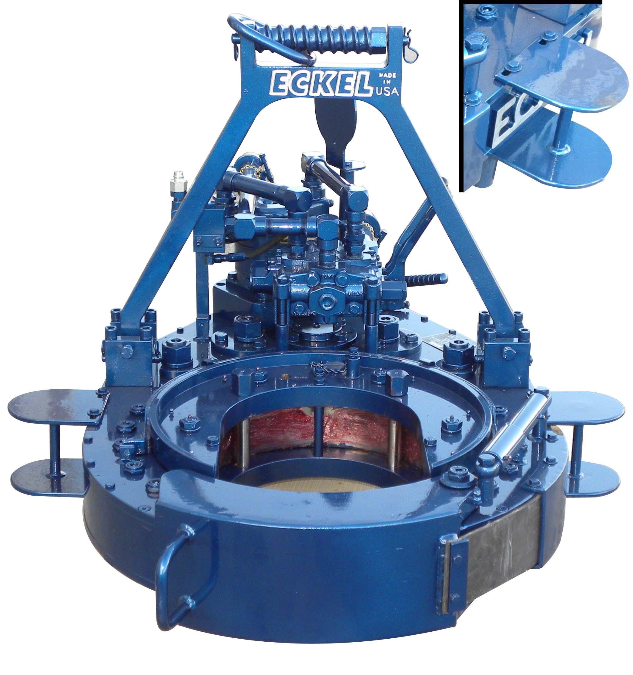
Referring now to FIGS. 4A-4G, multiple views of a power tong assembly 400 in accordance with one or more embodiments of the present disclosure are shown. The power tong assembly 400 includes a power tong 402 used for gripping and rotating tubular segments, particularly for making-up and breaking-out threaded connections, and also includes an interlock system 410. The interlock system 410 is operably coupled to the power tong 402 to selectively allow the power tong to rotate the tubular segment in one of the make-up and the break-out direction while also preventing the power tong 402 from rotating the tubular segment in the other of the make-up and the break-out direction. Accordingly, in this embodiment, the interlock system 410, or at least portions or components thereof, are positioned upon and operably coupled to a motor 404 of the power tong 402. The motor 404 may be a bi-directional hydraulic motor, in which the interlock system 410 may be used to disable the motor 404, such as by limiting hydraulic fluid supply to the motor 404, to prevent the power tong 402 from rotating the tubular segment in an undesired direction or at an undesired speed.
Along with the motor 404, the power tong 402 may include one or more handles 406 to set the power tong 402 in the make-up setting or the break-out setting. For example, in FIG. 4A, one of the handles 406 may be moved to set the power tong 402 in either the make-up setting or the break-out setting, while the other of the handles 406 may be moved to operate a lift cylinder operably coupled to the power tong 402 to selectively raise and lower the power tong 402. The power tong 402 may further include a handle 408 (e.g., speed shifting shaft) to set the power tong 402 in the high-speed setting or the low-speed setting. For example, in FIG. 4A, the handle 408 may be moved in one direction to set the power tong 402 in the high-speed setting or may be moved in another direction to set the power tong 402 in the low-speed setting.
As the interlock system 410 may include multiple portions or components, the interlock system 410 is shown in this embodiment as including a manifold 412, which may be formed as one or more housings, and a speed detection mechanism 414 (e.g., power tong gear position sensor 318). FIG. 4B shows a detailed view of the manifold 412, and FIG. 4C shows a detailed view of the speed detection mechanism 414. The manifold 412 may be positioned on the motor 404 of the power tong 402 and may have hydraulic fluid pumped through the manifold 412. As such, the manifold 412 may include hydraulic logic elements to selectively divert hydraulic fluid flow therethrough, such as including one or more valves, plugs, and/or switches to selectively divert the flow through the manifold 412. In particular, in this embodiment, the manifold 412 may include therewith or therein a selector mechanism 416, a check valve, an orifice or a needle valve, and an unloader valve.
The selector mechanism 416 may be included within the interlock system 410, and may be used as a tong operator interface to switch and move the interlock system 410 between the make-up setting and the break-out setting. Examples of the selector mechanism 416 are shown in FIGS. 4D-4F. In FIGS. 4D and 4E, the selector mechanism 416 is shown as a plug assembly 418 that includes one or more plugs. The plugs of the plug assembly 418 may be rearranged and positioned within the manifold 412 to set the interlock system 410 in a make-up setting (e.g., high-speed make-up setting), as shown in FIG. 4D, or to set the interlock system 410 in a break-out setting (e.g., high-speed break-out setting), as shown in FIG. 4E. Alternatively, the selector mechanism 416 is shown as a three-way valve 420 in FIG. 4F, such as a three-way ball valve, in which the three-way valve 420 may be set and moved between the make-up setting and the break-out setting.
The speed detection mechanism 414 may be operably coupled to the handle 408 that shifts the power tong 402 between the high-speed setting and the low-speed setting. Accordingly, the speed detection mechanism 414 may be positioned adjacent the handle 408, such as positioned on the bottom of the power tong 402. In this embodiment, the speed detection mechanism 414 may include a cam-operated valve 422. FIG. 4G shows a cross-sectional view of the cam-operated valve 422. As such, the cam-operated valve 422 is activated and moved between an open position and a closed position based on movement of a camming rod 424. The camming rod 424 may be coupled to the handle 408, and therefore the camming rod 424 may move with the handle 408 when shifting the power tong 402 between the high-speed setting and the low-speed setting. Accordingly, the cam-operated valve 422 may detect the speed of the power tong 402, such as if the power tong 402 is in the high-speed setting or the low-speed setting, based upon the position and movement of the camming rod 424.
Referring now to FIGS. 5A and 5B, multiple schematic views of a simplified hydraulic circuit 500 for a power tong assembly in accordance with one or more embodiments of the present disclosure are shown. As shown in this embodiment, the hydraulic circuit 500 includes a hydraulic motor 502 (e.g., bi-directional hydraulic motor), such as the motor 404 shown in FIG. 4A, and a directional control valve 504 (e.g., four-way, three-position directional control valve) that controls fluid flow to the hydraulic motor 502. The directional control valve 504 may include or be operably coupled to the handles 406 of the power tong 402. As such, the directional control valve 504 may be used to control the direction of rotation of the hydraulic motor 502, and therefore may be used to move the power tong 402 between the make-up setting and the break-out setting. Hydraulic fluid may be provided along a pressure flow path 550 and flow through a motor inlet flow path 552 into the directional control valve 504. The directional control valve 504 may then be used to selectively flow the hydraulic fluid into either the A-side or the B-side of the hydraulic motor 502, depending on the desired rotation of the power tong 402. Hydraulic fluid may then return from the hydraulic motor 502 back into the directional control valve 504, in which hydraulic fluid may then be provided to a return flow path 556 through a motor outlet flow path 554.
The directional control valve 560, as shown in the embodiment in FIGS. 5A and 5B, may be opened from operation of either a directional control valve 564 or a directional control valve 566 fluidly coupled in parallel to the directional control valve 560 along the case drain flow path 562. The directional control valve 564 (e.g., two-way, two-position directional control valve) may include an interlock valve that is movable between the open and closed position based upon an open or closed position of a door of the power tong 402. If the door of the power tong 402 is opened, the directional control valve 564 may relieve pilot pressure to the directional control valve 560 along the case drain flow path 562, thereby opening the directional control valve 560 and preventing operation of the hydraulic motor 502.
The hydraulic circuit 500 may further include a directional control valve 576 (e.g., three-way, two-position directional control valve), which may be the cam-operated valve 422 of the speed detection mechanism 414 shown in FIGS. 4A, 4C, and 4G. The directional control valve 576 may be movable between the open and closed position based upon if the power tong 402 is in the high-speed setting and the low-speed setting. As such, in this embodiment, the directional control valve 576 may be in the open position when the power tong 402 is in the high-speed setting, thereby fluidly coupling the pilot flow path 574 to the pilot flow path 568. Further, as shown in FIGS. 5A and 5B, the directional control valve 576 may be in the closed position when the power tong 402 is in the low-speed setting, thereby preventing fluid from flowing from the pilot flow path 574 to the pilot flow path 568. Furthermore, the hydraulic circuit 500 may include a check valve 578 and an orifice or a needle valve 580. The check valve 578 and the needle valve 580 may be in parallel with each other, as shown, and may be fluidly coupled to the pilot flow path 574 or the pilot flow path 568.
In operation, the selector mechanism 570 may be used to either allow fluid flow through the A-side motor flow path 572A or the B-side motor flow path 572B and into the pilot flow path 574. When the A-side motor flow path 572A is open with fluid allowed to flow therethrough, the A-side of the hydraulic motor 502 is not operational. For example, hydraulic fluid may be provided along the motor inlet flow path 552, into the directional control valve 504, and towards the A-side of the hydraulic motor 502. As the A-side motor flow path 572A is open, hydraulic fluid will flow into the A-side motor flow path 572A and continue along the pilot flow path 574. If the directional control valve 576 is present and open (e.g., the power tong 402 is in the high-speed setting), hydraulic fluid may flow from the pilot flow path 574 to the pilot flow path 568 to provide pilot pressure to the directional control valve 566. When pilot pressure is received along the pilot flow path 568 to the directional control valve 566, the directional control valve 566 will open, thereby relieving pilot pressure to the directional control valve 560 along the case drain flow path 562, opening the directional control valve 560, and preventing operation of the hydraulic motor 502.
In an embodiment in which hydraulic fluid received through the A-side of the hydraulic motor 502 causes the power tong 402 to make-up threaded connections with a tubular segment, the right side of the directional control valve 504 may be used as the make-up setting for the power tong 402, and the opening the B-side motor flow path 572B may be used as the make-up setting for the selector mechanism 570 (e.g., selector mechanism 416). In such an embodiment, the hydraulic motor 570 may, thus, be disabled when the directional control valve 504 is switched to the left side for the break-out setting of the power tong 402, thereby disabling and preventing the hydraulic motor 570, and the power tong 402, from operating in the break-out setting when the interlock system 410 is in the make-up setting.
Similarly, in an embodiment in which hydraulic fluid received through the B-side of the hydraulic motor 502 causes the power tong 402 to break-out threaded connections with a tubular segment, the left side of the directional control valve 504 may be used as the break-out setting for the power tong 402, and the opening the A-side motor flow path 572A may be used as the break-out setting for the selector mechanism 570 (e.g., selector mechanism 416). In such an embodiment, the hydraulic motor 570 may, thus, be disabled when the directional control valve 504 is switched to the right side for the make-up setting of the power tong 402, thereby disabling and preventing the hydraulic motor 570, and the power tong 402, from operating in the make-up setting when the interlock system 410 is in the break-out setting.
Further, as discussed above, the directional control valve 566 (e.g., unloader valve) may be used as a disabling portion within the interlock system to disable and prevent rotation of the power tong based a speed detection portion (e.g., a directional control valve 576 and/or a cam-operated valve 422) and the direction detection portion (e.g., selector mechanism 570). For example, when pilot pressure is received along the pilot flow path 568 to the directional control valve 566, the directional control valve 566 will open, thereby relieving pilot pressure to the directional control valve 560 along the case drain flow path 562. This enables the directional control valve 560 to open, in which hydraulic fluid then flows along the bypass flow path 558 instead of the motor inlet flow path 552, thereby disabling and preventing the hydraulic motor 502 from operation.
Accordingly, a power tong assembly including a power tong and an interlock system in accordance with the present disclosure may include one or more advantages, such as by decreasing the likelihood of an accident when operating a power tong. In particular, the interlock system is configured to selectively allow the power tong to rotate the tubular segment in one of the first direction and the second direction while preventing the power tong to rotate the tubular segment in the other of the first direction and the second direction. As such, the interlock system may be used to prevent the power tong from operating in a direction unintended by a tong operator, thereby preventing damage to the power tong, to the tubular segments handled by the power tong, and the tong operator.

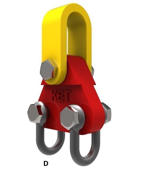
Employee #1 worked as a driller"s helper on one of two, 3-man crews drilling an 18 in. diameter replacement water well for the city of Holly Springs, MS. His job was to operate the pipe tongs (wrench) at the rear of a portable drilling rig on the day shift on Wednesday, February 15, 1989, a misty, cold day. At 8:00 a.m., the day shift crew began removing the twelve pipe sections plus an 18 in. diameter dummy casing section which had been strung into the hole by the night crew. The day crew had successfully removed 8 pipe sections and Employee #1 had latched the tong jaws around the ninth pipe section above the threaded pipe joint. But he did not step back when the driller engaged the rotary table"s transmission, and the rotary turning clockwise applied torque to the bottom tenth section of pipe. A 7/16 in. diameter by 4.302 ft long wire rope snub-line, which was restraining the 2.182 ft long tong handle, snapped when the rotary transmission"s torque was applied. The tong handle was free to rotate, and struck Employee #1 in the left mid-chest. This severe chest trauma broke no bones but caused cardiac arrest. Employee #1 was transported to Marshall County Hospital, but died after efforts on site and at the hospital failed to restart his heart. The tongs were a type D drill pipe tubing and casing tong set by Web Wilson, a division of Cooper Industries, Martin-Decker Division, Woodlawn, TX. The rig was a Gardner Denver wide mast-40, portable drilling rig, serial #4235. The wire rope snub-line was preformed steel, 19 by 7, rotation resistant, right regular lay with IWRC (independent wire rope core), with red paint marking several strands (this most likely was a Leschen Wire Rope Company brand cable). Causal factors include: the snubline was too long, breakout cathead and tongs were not being used, and Employee #1 was in the wrong position.
API Spec 7 2010 also includes a comprehensive listing of best practice guidelines for just about any drilling and well servicing equipment operations you can think of.

Rotary Tables, Rotary Bushings, Rotary Slips, Piston Mud Pump Components, Drawworks Components, Spiders, Manual Tongs, Safety Clamps Not used as Hoisting Devices, BOP Handling Systems, Pressure Relieving Devices for High-Pressure Drilling Fluid Circulating Systems, Snub-Lines for Manual and Power Tongs, Slip Bowls, High Pressure Mud and Cement Hoses at FSL 0, 1, and 2
Hoisting Sheaves, Traveling Blocks and/or Hook Blocks; Block-to-Hook Adapters, Connectors and Link Adapters, Drilling Hooks, Tubing and Sucker Rod Hooks; Elevator Links, Casing, Tubing and Drill Pipe Elevators, Sucker Rod Elevators; Rotary Swivel Bail Adapters, Rotary Swivels; Power Swivels, Power Subs; Spiders (if capable of being used as elevators), Wireline Anchors; Drill-String Motion Compensators; Kelly Spinners (if capable of being used as hoisting equipment); Pressure Vessels and Piping Mounted onto Hoisting Equipment; Safety Clamps (if capable of being used as hoisting equipment); Guide Dollies for Traveling Equipment at PSL 1 and 2
Bright or Drawn-Galvanized Wire Rope; Mooring Wire Rope; Torpedo Lines; Well-Measuring Wire; Well-Measuring Strand; Wire Guy Strand; Structural Rope and Strand
Choke and Kill Manifold Buffer Chamber; Drilling Choke Actuators; Drilling Choke Controls; Drilling Chokes; Rigid Choke and Kill Lines; Flexible Choke and Kill Lines at FSL 0, FSL 1, FSL 2 and/or FSL 3

Manufacturer of Line Pipe - Plain End at PSL 1; Manufacturer of Line Pipe - Plain End at PSL 2; Manufacturer of Line Pipe - Threaded and Coupled; Manufacturer of Line Pipe Couplings; Processor of Line Pipe - Plain End at PSL 1; Processor of Line Pipe - Plain End at PSL 2; Processor of Line Pipe - Threaded and Coupled; Threader
Rotary Tables, Rotary Bushings, Rotary Slips, Piston Mud Pump Components, Drawworks Components, Spiders, Manual Tongs, Safety Clamps Not used as Hoisting Devices, BOP Handling Systems, Pressure Relieving Devices for High-Pressure Drilling Fluid Circulating Systems, Snub-Lines for Manual and Power Tongs, Slip Bowls, High Pressure Mud and Cement Hoses at FSL 0, 1, and 2
Hoisting Sheaves, Traveling Blocks and Hook Blocks; Block-to-Hook Adapters, Connectors and Link Adapters, Drilling Hooks, Tubing and Sucker Rod Hooks; Elevator Links, Casing, Tubing and Drill Pipe Elevators, Sucker Rod Elevators; Rotary Swivel Bail Adapters, Rotary Swivels; Power Swivels, Power Subs; Spiders (if capable of being used as elevators), Wireline Anchors; Drill-String Motion Compensators; Kelly Spinners (if capable of being used as hoisting equipment); Pressure Vessels and Piping Mounted onto Hoisting Equipment; Safety Clamps (if capable of being used as hoisting equipment); Guide Dollies for Traveling Equipment at PSL 1 and 2
Bright or Drawn-Galvanized Wire Rope; Mooring Wire Rope; Torpedo Lines; Well-Measuring Wire; Well-Measuring Strand; Wire Guy Strand; Structural Rope and Strand
Choke and Kill Manifold Buffer Chamber; Drilling Choke Actuators; Drilling Choke Controls; Drilling Chokes; Rigid Choke and Kill Lines; Flexible Choke and Kill Lines at FSL 0, FSL 1, FSL 2 and/or FSL 3

15, The driller adopts truck power and technical method of foam drilling, which solves the problems of deficiency of water source and electrical source in field drilling work.
18, The driller ensures that the drilling line is wrapped with the soft wire or tape at both sides of the mark before cutting the drilling line with the hydraulic line cutter.
Safety compliance guidelines are administered by the Occupational Safety and Health Administration (OSHA). Exposures to hazards present in oil and gas well drilling, servicing and storage are addressed in specific OSHA standards for general industry 29 CFR 1910.
Employees are responsible for following safe work practices and company rules, and for preventing accidents and injuries. Management will establish lines of communication to solicit and receive comments, information, suggestions and assistance from employees where safety and health are concerned.
Stand outside of the tong swing radius when breaking pipe, and use proper tong latching techniques and proper hand and finger placement on the tong handles.
Casing is pipe usually larger in diameter and longer than drill pipe, and is used to line the hole. Casing operations occur periodically throughout the drilling process, starting with the surface casing, intermediate casing and then the production string process. To ensure worker safety during casing operations, review the following hazards and potential safety solutions.
Oil drilling is an intricate process that involves lots of manpower and skill. With so many moving parts and hands on deck, you not only need to perform your job, you need to perform it with safety in mind.
On the S-55 McCormack ran a large hydraulically powered wrench called "power tongs" which, because of its size, is suspended from the oil derrick. As lengths of metal casing were fit together to be lowered into the well hole, McCormack placed the jaws of the tongs around the pipe and the machine tightly screwed the pieces together. Because of the great torque generated by the tongs, it is necessary to anchor the wrench itself so that the machine cannot spin freely around the pipe and injure the operator. The "snub line," a metal cable attached to a stationary object, provides the necessary anchor.
On May 24, 1973, drilling activity aboard the S-55 ceased while the workers awaited the arrival of a set of power tongs to replace a pair that had broken down earlier. When the replacement tongs arrived Kenton Boudreaux, McCormack"s relief operator and the only other Sladco employee on the barge, rigged the tongs and operated them without difficulty. The very first time McCormack ran the tool, however, something went wrong and McCormack was seriously injured.
Defendants" major claim on appeal2 is that the evidence adduced at trial was insufficient as a matter of law to generate a factual question regarding the negligence of either Noble or Chevron. Defendants also contend that plaintiff"s injuries were caused by malfunction of the tongs and the negligence of Sladco and McCormack rather than by acts or omissions of Noble and Chevron. They argue that the district court erred in not granting their motions for directed verdict and for judgment notwithstanding the verdict.
Noble"s intimate involvement in the casing operation is undisputed. The lengths of two and three-eights inch diameter casing tubing were stored on the S-55 on a pipe rack next to the derrick. By means of a crane-like device, Noble employees hoisted pieces of the tubing into the derrick where the "stabber," also a Noble employee, took control of them. The stabber stood on the "monkey" or stabbing board above the floor of the rig and, as lengths of pipe came to him, unhooked them and stabbed the male end of the tube into the box end of the last length of pipe in the string already extending into the well hole. The stabber then began to thread the pipes together to ensure that the connection was started straight. At that point under the procedure employed by Noble and Sladco on the S-55, Sladco"s tong operator attached the jaws of the tongs to the joint and applied light torque sufficient to permit the connection to be tested for leakage through the use of a device known as a "gator hawk."3 While the Sladco tong operator put light torque on the connection, the stabber steadied the upper end of the pipe with his hands. After the gator hawk operator checked the joint, with the stabber still holding the pipe, heavy torque of the tongs finished the connection. Then the stabber fastened the "elevators" to the top of the pipe and lowered it into the well where it was locked into place. The whole procedure was then repeated with the next length of casing.
At trial there was testimony that if the cable of the snub line is too long the tongs will rotate too far around the casing and the operator may be trapped by the snub line and seriously injured. McCormack was hurt when the tongs rotated too far and, at his deposition, he stated that he believed the cause of his accident was the improper length of the snub line. Kenton Boudreaux, however, testified that when he rigged the replacement tongs he used the snub line that had been attached to the tongs that had broken down earlier and that he did not alter the length of the cable. Moreover, Boudreaux stated that, when he checked the operation of the new tongs, the length of the snub line was correct. At trial other witnesses, all Noble employees, also testified that the snub line appeared to be the proper length.
At trial McCormack"s theory of the cause of his injuries was that under the power of the tongs the tubing bent toward the snub line even though the snub line was correctly rigged. As a result of the bending of the pipe, the length of the cable was in effect increased greatly. The tongs rotated about the pipe, trapped Jesse McCormack in the snub line, and seriously injured him.4
Defendants attempted to explain the bending of the pipe in terms of McCormack"s negligence or malfunction of the tongs. Noble employees testified that they heard the machine "run away" at full throttle although the tongs were supposed to apply only light torque at the stage of operation then being performed. Further, witnesses stated that McCormack"s hand was still on the throttle when he was extricated from the tangle of pipe, tongs, and snub line. Evidence presented to the jury, however, also supports the theory that the tongs did not malfunction. Kenton Boudreaux operated them with no difficulty before the accident and Sladco"s repair records clearly indicate that, although shortly after the accident Sladco checked the tongs McCormack had used when he was hurt, the machine needed no repair. Indeed, for a full year following the accident no repairs were made on the tongs that related in any way to the alleged malfunction.
As stated above, during the entire procedure of making the connection between the two lengths of casing, the tubing was secured only at the floor of the rig. The only stability above the tongs resulted from the stabber holding the top of the tubing in his hands. Witnesses agreed that the method used by Noble in running the tubing was one of two generally employed in the industry. Under the procedure not used by Noble, the elevators that lower tubing into the well hole6 help secure the top of the tubing. In following that method, after light torque is applied to the connection and while the gator hawk operator tests the connection, the elevators are lowered over the top of the pipe before the joint is finally tightened with high torque. The weight of the elevators and the assembly to which they are attached would greatly lessen the likelihood of the pipe bending under the torque from the tongs, even if the elevators are placed over the end of the pipe but not engaged.7 Plaintiff"s expert testified that the accident would have been "very unlikely" had the elevators been over the top of the casing when McCormack applied torque.
According to plaintiff"s expert, the stabber could have started the first few threads of the connection and then placed the elevators loosely over the end of the pipe before McCormack applied any torque from the tongs. This method was not a commonly accepted procedure, however, because on the S-55 Noble and Sladco were running a "dual string" of casing into the well. In order to do this, connections are made on both lines before the elevators are placed over the pipes to lower them into the hole. McCormack used "special clearance" tongs when he was injured, tongs that could fit between the two lengths of pipe extending into the well. The gator hawk being used to test the connections, however, was too large unless the strings of pipe were manually spread apart. With the elevators on, this would not be possible. Nevertheless, the expert testified that in his opinion the operation would have been safer had the elevators been hooked up before any torque was applied, taken off to permit testing the connections, and then reattached for the final torque before the pipes were lowered into the hole. In the expert"s view, the cost of this procedure over those commonly employed would only be some lost time about six minutes per hour. Considering all the evidence, the jury properly could have concluded that Noble"s method of operating constituted negligence that was a substantial factor leading to McCormack"s injury.8

This website is using a security service to protect itself from online attacks. The action you just performed triggered the security solution. There are several actions that could trigger this block including submitting a certain word or phrase, a SQL command or malformed data.


 8613371530291