
power tong truck for sale free sample

Tongs - Power - BJ sucker rod tong adopts advanced sucker rod or tubing technology and has a compact structure, high reliability and is safe and convenient to operate.
Tongs - Power - New Carter Tool Co. Inc., CT93R Hydraulic powered tubing tong. Complete with 2-3/8" to 3-1/2" jaw assemblies, standard motor, torque gauge assembly, pressure relief valve... More Info
Tongs - Power - New Carter Tool Co., Inc. 5-1/2" CTSX Hydraulic Tubing Tong with heavy case and cover; complete with rigid hanger assy., suspension spring assy., front end control assy.,... More Info
Tongs - Power - New Carter Tool Co. Inc. M-Series power sucker rod tongs, complete with spring hanger assy., gate assy., front end control assy., pressure gauge assy., two 90 degree XH s... More Info
Tongs - Power - New Carter Tool Co., Inc. 4-1/2" RSX Hydraulic Tubing Tong with heavy case and cover; complete with rigid hanger assy., suspension spring assy., front end control assy., ... More Info
Tongs - Power - D D 58-93-2-R Power Tubing Tong is smaller, lighter, and faster than the Foster 5893R. The D D 58-93-2-R Tong is capable of gripping tubulars from 1 5/16" to 7" o.d. More Info
Tongs - Power - FARR TONG MODEL KT 14,000 RINEER GA37 MOTOR, LIFT VALVE ASSEMBLY TORQUE CAPACITY: 50,000 FT/LB SIZE RANGE 4 1.2-14 WITH SAFETY DOOR MOST SIZES OF FARR POWER TONGS ARE IN ... More Info
Tongs - Power - FARR TONG MODEL KT20,000 STAFFA 080 MOTOR, LIFT VALVE ASSEMBLY TORQUE CAPACITY: 50,000 FT/LB SIZE RANGE: 7-20 MOST SIZES OF FARR POWER TONGS ARE IN HOUSTON, IN STOCK READ... More Info
Tongs - Power - FARR MODEL KT5500 HYDRAULIC TUBING TONG C/W 2 SPEED RINEER MOTOR, SIZE RANGE: 2-3/8 IN. - 5-1/2 IN. OD, TORQUE RTED: 18,700 FT/LB C/W SAFETY DOOR MOST SIZES OF FARR POWER... More Info
Tongs - Power - FARR TONG MODEL KT5500 TORQUE CAPACITY: 18000 FT/LB SIZE RANGE: 2 1/16-5 1/2 OD WITH SAFETY DOOR MOST SIZES OF FARR POWER TONGS ARE IN HOUSTON, IN STOCK READY FOR IMMEDIA... More Info
Tongs - Power - FARR TONG MODEL KT5500 5 1/2 IN. TONG TORQUE CAPACITY: 18,000 FT/LB SIZE RANGE: 2 1/16-5 1/2 IN. OD, RINEER 15-13 MOTOR, HIGH TORQUE CLINCHER BACKUP TRIPLE VALVE ASSEMBLY... More Info
Tongs - Power - FARR TONG MODEL KT7585 TORQUE CAPACITY: 25000 FT/LB SIZE RANGE: 2 1/16-8 5/8 OD WITH SAFETY DOOR MOST SIZES OF FARR POWER TONGS ARE IN HOUSTON, IN STOCK READY FOR IMMEDIA... More Info
Tongs - Power - FARR TONG MODEL KT7585 8 5/8 IN. TONG TORQUE CAPACITY 25,000 FT/LB SIZE RANGE: 2 1/16-8 5/8 IN. OD, RINEER 15-15 MOTOR CLINCHER BACKUP, TRIPLE VALVE MOST SIZES OF FARR PO... More Info
Tongs - Power - FARR TONG MODEL LW9625 TORQUE CAPACITY 12000 FT/LB SIZE RANGE 2 7/8 -9 5/8 OD WITH SAFETY DOOR MOST SIZES OF FARR POWER TONGS ARE IN HOUSTON, IN STOCK READY FOR IMMEDIATE... More Info
Tongs - Power - Farrs newest tubular connection tool offers a significantly reduced rig footprint, while continuing to deliver power & uncompromising reliability. The simple design drast... More Info
Tongs - Power - Farr Canada"s newest tubular connection tool offers a significantly reduced rig footprint, while continuing to deliver power and uncompromising reliability. The simple de... More Info

This website is using a security service to protect itself from online attacks. The action you just performed triggered the security solution. There are several actions that could trigger this block including submitting a certain word or phrase, a SQL command or malformed data.
This website is using a security service to protect itself from online attacks. The action you just performed triggered the security solution. There are several actions that could trigger this block including submitting a certain word or phrase, a SQL command or malformed data.
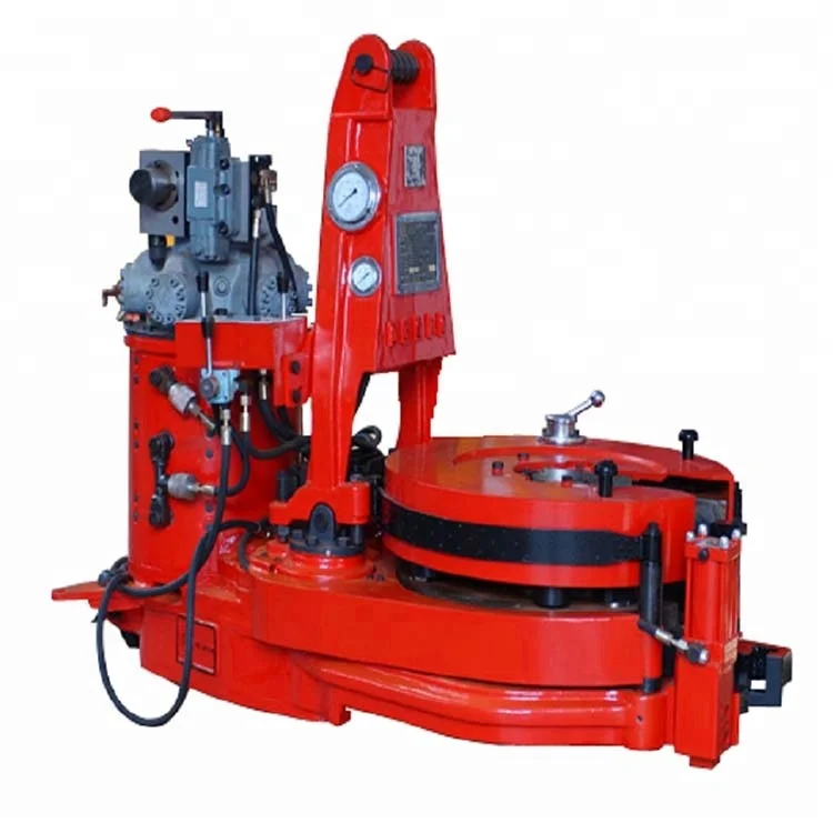
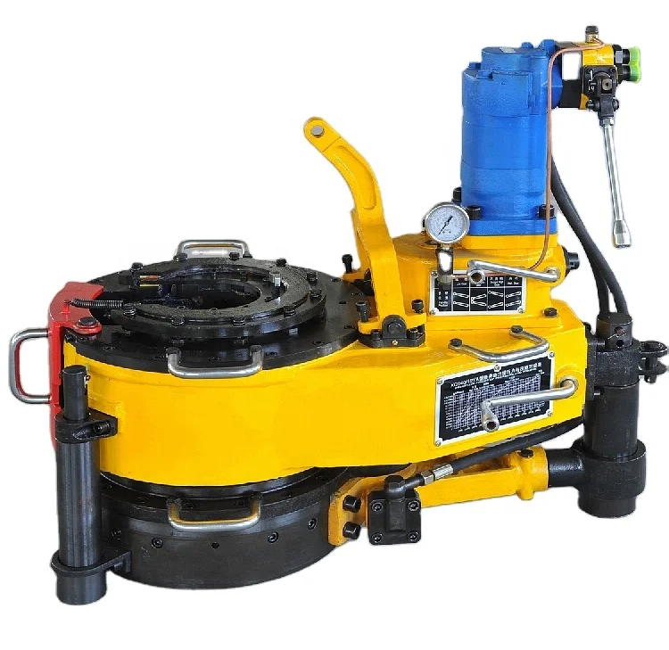
Power tongs are an essential tool in the drilling industry and are used to make up, break out, apply torque and to grip the tubular components. We are distributors for both Starr Power Tongs and McCoy Global hydraulic power tongs in multiple sizes and torque ranges from high torque to low torque that can be used to run both casing, drill pipe and tubing. When determining which power tong is best for your project, you will want to select the power tong that best fits your tubular size ranges and torque required.
All of our power tongs are available with either the McCoy\\\\\\\\\\\\\\\"s patented WinCatt data acquisition software recently updated to the MTT systems or AllTorque\\\\\\\\\\\\\\\"s computer monitoring system for all the torque and turn control system needed in today\\\\\\\\\\\\\\\"s market for the making of tubular connections. Discover our wide selection of McCoy and Starr casing tongs, tubing tongs and power tongs for sale below!
You are a manufacturer of wooden furniture in California. You plan to expand your operations to meet the growing demands of your customers. As a result, you need to purchase new manufacturing equipment that includes a table saw, a drill press, and a lathe. You want to know if your purchases will qualify for the Manufacturing, Research and Development partial exemption.
First, you need to find out whether your company is a qualified person for the purposes of the partial exemption. You have been primarily engaged in business for several years as a manufacturer of wooden furniture. You determine your company"s North American Industry Classification System (NAICS) code to be 337122. Since the NAICS code for your primary line of business is described within the range of 3111 to 3399, you determine that your company does qualify for the partial exemption.
Next, you examine whether the equipment you are purchasing qualifies for the partial exemption and whether it will be used in a qualifying manner. You are purchasing machinery and equipment that has a useful life greater than one year. You plan to use the equipment at least 50 percent of the time for manufacturing purposes. Therefore, you have determined that your purchases qualify for the partial exemption.
Now that you have determined that both your business and purchases qualify for the partial exemption, you are ready to start buying equipment. You and whether it will be used in a qualifying manner. need to download the Partial Exemption Certificate for Manufacturing, Research and Development Equipment. Fill it out, print it, and sign it. Then give it to the retailer of the equipment at the time you make your purchase.
The retailer will charge or collect from you at a reduced tax rate thereby saving you 3.9375 percent in sales or use tax on the purchase of your equipment.
In order to be considered a qualified person for the partial exemption, you must be primarily engaged in a line of businesses described in North American Industry Classification System (NAICS) code 3111 to 3399 for manufacturers, 541711 or 541712 if you are engaged in research and development or, beginning January 1, 2018, 22111 to 221118, and 221122 for qualifying electric power generators or distributors.
NAICS codes are used to classify business establishments by a six-digit code system. The first four digits represent the industry group, and the last two digits represent the specific industry. For example, a business that manufactures cardboard boxes will have a NAICS code of 322211:
Your business" NAICS code is that which best describes your line of business, based on either its primary revenues or primary operating expenses. If there is no six-digit NAICS code for your specific line of business, you may still qualify for the partial exemption if your business activities are reasonably described in a qualifying four-digit industry group.
Please note: The six-digit NAICS codes for research and development were changed in the 2017 edition. In general, the 2012 NAICS codes 541711 and 541712 were replaced by 2017 codes 541713 – 541715. Again, only the 2012 NAICS codes are relevant in determining whether a person is engaged in a qualifying line of business.
Most businesses or entities will have one NAICS code that best describes their line of business. However, if your entity is not primarily engaged in a line of business described in a qualifying NAICS code and you operate separate establishments within the entity, that constitute separate "cost centers" or "economic units," a separate establishment may qualify for the partial exemption if it is primarily engaged in a line of business described by a qualifying NAICS code. You must keep separate books and records for each establishment.
Generally, for purposes of the partial exemption, property that is capitalized and depreciated on your state income or franchise tax returns will be regarded as having a useful life of one or more years.
If property is not capitalized and depreciated for income tax purposes, it will be presumed that the property does not have a useful life of one or more years and will not qualify for the partial exemption. However, transactions involving certain property that is not capitalized and depreciated for state income or franchise tax purposes may qualify for the partial exemption in the following situations:
The cost of qualifying property is deducted under Revenue and Taxation Code (RTC) sections 17201 and 17255 or 24356 (similar to Section 179 of the Internal Revenue Code, but subject to lower deduction thresholds for state purposes).
Individual materials and fixtures purchased and installed as a component part(s) of a special purpose building. The special purpose building, as a whole, will be depreciated for tax reporting purposes.
Establishments that are primarily engaged in research and development in biotechnology, physical engineering, and life sciences may qualify for the partial exemption. To qualify for the partial exemption, the establishment must be classified under one of the following two North American Industry Classification System (NAICS) codes: 541711, 541712.
(As noted above, the six-digit NAICS codes for research and development were changed in the 2017 edition. In general, the 2012 NAICS codes 541711 and 541712 were replaced by 2017 codes 541713 – 541715. Again, only the 2012 NAICS codes are relevant in determining whether a person is engaged in a qualifying line of business.)
If you are primarily engaged in research and development as described above, your purchase or lease of machinery, equipment, or other devices that have a useful life of one or more years, and which will be used primarily for research and development will generally qualify for the partial exemption.
A university has a research and development department. Research and development is not the primary line of business of the University. Therefore, as an entity, the University is not primarily engaged in a line of business described by a qualifying NAICS code. However, if the University can establish that the research and development department is a separate "establishment," then the research and development department may be qualified for purposes of the partial exemption. To be considered a separate establishment, the University must keep separate books and records for the research and development department.
On or after January 1, 2018, businesses that are primarily engaged in electric power generation or distribution may qualify for the partial exemption. To qualify for the partial exemption, the business must be primarily engaged in a line of business described under one of the following North American Industry Classification System (NAICS) codes (2012 edition).
In general, qualifying electric power generators includes businesses primarily engaged in operating power generation facilities that convert other forms of energy, such as water power, fossil fuels, nuclear power, and solar power, into electrical energy. Establishments in this industry produce electric energy and provide electricity to transmission systems or to electric power distribution systems.
For purposes of this partial exemption, solar electric power generators include those businesses that are primarily engaged in operating solar electric power generation facilities that use energy from the sun to produce electric energy. The energy produced in these businesses is provided to electric power transmission systems or to electric power distribution systems.
If you are a qualified person, your purchase of solar equipment or other electric power generating or producing equipment used to primarily run your manufacturing equipment may qualify for the exemption (see the Solar Power Equipment topic on this page).
The following are categories and examples of tangible personal property (TPP) that may be used in the generation or production and/or storage and distribution of electric power (in some cases as part of a special purpose building). As always, whether or not the sale or use of a particular item of TPP qualifies for the partial exemption is based on whether the three basic elements have been met: qualified person, qualified tangible personal property, and qualified use. (See Qualifications tab).
Equipment that converts renewable energy from sunlight into electricity, either directly using photovoltaics, indirectly using concentrated solar power, or a combination.
Energy conversion monitors and controllers, communications equipment, Supervisory Control and Data Acquisition (SCADA) equipment, protection equipment, power quality and metering equipment
You are a new company that manufactures breakfast cereal and you are planning to acquire a new oven for manufacturing. You have decided to lease the oven instead of purchasing it and you want to know if your lease of the oven qualifies for the partial Manufacturing, Research and Development exemption.
Will lease the oven for more than one year. The lessor did not make an election to report tax on the purchase price of the oven and will therefore collect tax on the lease receipts.
Your lease of the oven qualifies for the partial exemption. When you enter into the lease agreement, you can provide the leasing company a Partial Exemption Certificate for Manufacturing, Research and Development Equipment to obtain the partial exemption from sales and use tax on the lease payments.
During your lease agreement, the leasing company will charge you a monthly lease payment, with tax separately added. However, the Manufacturing, Research and Development partial exemption is only in effect until June 30, 2030. Any lease payments due after June 30, 2030, will be subject to the full sales and use tax rate even if the lease began during the exemption period.
You are a construction contractor hired by a manufacturer to build a special purpose building. Your sales or purchases of materials or fixtures that you furnish and install in the performance of a construction contract for a qualified person may qualify for the partial exemption.
Please note, beginning January 1, 2018, the definition of "qualified tangible personal property" expanded to include special purpose buildings and foundations used as an integral part of the generation or production, storage or distribution of electric power.
In order to document that the partial exemption applies, you must obtain from the qualified person, and keep in your records a valid partial exemption certificate signed by the qualified person. The exemption certificate must indicate that the qualified person and special purpose building meet the qualifications for the partial exemption, and that the property will be used in a qualifying manner. For this purpose, you may obtain a Partial Exemption Certificate for Manufacturing, Research and Development Equipment (CDTFA-230-M) prescribed by the CDTFA, or a similar form.
Depending on the percentage of usable volume of a building being used in a qualifying manner, the entire building or only a portion of the building may qualify for the partial exemption (see Special Purpose Buildings below). In the event that all materials and fixtures do not qualify for the partial exemption, it is necessary that the exemption certificate accurately lists the property to be purchased subject to the partial exemption.
As explained on the Industry Guide for Construction Contractors, the performance of a construction contract generally involves the furnishing and installation of materials and/or fixtures that are incorporated into realty. Due to the unique nature of the manufacturing, research and development partial exemption and the ability of the qualified person to pass the partial exemption on to a construction contractor that is furnishing and installing materials and/or fixtures as part of the construction of a special purpose building, a detailed explanation of the application of tax and the documentation requirements is provided below.
As a construction contractor, you are generally a consumer of materials that you furnish and install in the performance of a construction contract. Therefore, once you have obtained the required form CDTFA-230-M, Partial Exemption Certificate for Manufacturing, Research and Development Equipment" or similar form from the qualified person indicating that the partial exemption applies, you may purchase materials to be furnished and installed on the special purpose building at the partially exempt rate by issuing a form "CDTFA 230-MC, Construction Contracts-Partial Exemption Certificate for Manufacturing, Research and Development Equipment" to your suppliers.
As a construction contractor, you are generally regarded as a retailer of fixtures that are furnished and installed in the performance of a construction contract. You may issue a resale certificate when purchasing fixtures from a vendor. You may purchase fixtures for resale and sell them subject to the partial exemption to the qualified person.
A construction contractor might install machinery and equipment in connection with a construction contract. Such a sale of machinery and equipment is considered a sale and installation of tangible personal property, rather than an improvement to realty. As with a fixture, the construction contractor may generally purchase the property for resale and the subsequent sale to the qualified person will be subject to the partial exemption (except where the retailer is the subcontractor, as discussed below.)
The same rules discussed above apply when subcontractors are hired by a prime or general contractor to construct all or part of a special purpose building for the qualified person. In order to document that the partial exemption applies to the contract to construct the special purpose building, the subcontractor must obtain from the prime contractor and retain in its records a copy of the CDTFA-230-M, Partial Exemption Certificate for Manufacturing, Research and Development Equipment or similar form that the qualified person provided to the prime contractor. The subcontractor must also obtain and retain in its records a CDTFA-230-MC, Construction Contracts - Partial Exemption Certificate for Manufacturing, Research and Development Equipment signed by the prime contractor for property the subcontractor is furnishing and installing for the prime contractor in order to document that the partial exemption applies. The subcontractor may issue the necessary documentation as discussed above to their vendor, depending on whether the subcontractor is a consumer or a retailer of the property that is furnished and installed.
The qualified person is responsible for issuing the CDTFA-230-M as evidence that the construction is for qualified tangible personal property. A prime or general contractor will be responsible for issuing a CDTFA-230-MC to a supplier of materials or fixtures if purchased tax-paid. In addition, if the person furnishing and installing the materials is a subcontractor, the prime or general contractor will also need to provide the subcontractor with a copy of the CDTFA-230-M issued by the qualified person. Subcontractors will need to also issue a CDTFA-230-MC to their suppliers of materials or fixtures if purchased tax-paid.
Qualified persons are responsible for tracking their purchases to ensure they do not exceed the $200 million annual cap. All materials consumed by a contractor or subcontractor, or fixtures, machinery or equipment sold by a contractor or subcontractor in the performance of a contract to construct or modify a special purpose building count against the $200,000,000 annual limit of the qualified person. All construction contractors, including subcontractors, must make available cost information regarding all items sold or used in performance of a qualifying construction contract for purposes of tracking the qualified person"s $200,000,000 yearly exemption limit.
If you construct a new special purpose building or modify an existing structure that is designed and constructed, or reconstructed, for manufacturing or research and development, or, beginning January 1, 2018, for the generation or production, storage or distribution of electric power, your purchases of materials and fixtures that become part of the building, and machinery and equipment installed in the building, may qualify for the partial exemption.
In order to qualify (be eligible), the special purpose building must be used for manufacturing, processing, refining, fabricating, recycling, or it may be used as a research or storage facility for these processes. Buildings such as warehouses, solely used to store product after it has completed the manufacturing process, are not eligible for the partial exemption.
For example, a semiconductor manufacturer is constructing a building for manufacturing microchips. The building is designed and constructed with certain requirements to control temperature, humidity, and contaminants that are necessary for microchip production. Materials and fixtures that become a component part of the building, as well as machinery and equipment purchased and installed in the building, are qualifying property for the partial exemption.
All materials and fixtures that become a component part of the building will qualify for the partial exemption if no more than one-third (1/3) of the building"s total usable volume (generally Length x Width x Height) is devoted to a non-qualifying use, such as administrative purposes, parking, break rooms, etc. However, in those instances where more than one-third (1/3) of the total usable volume is devoted to a non-qualifying use, only the materials and fixtures that become a component part of the building that is used in manufacturing, processing, refining, fabricating, or recycling, or as a research or storage facility for these processes, or the generation or production, storage or distribution of electric power will be qualifying property for the partial exemption.
ABC R&D Inc. is constructing a new research facility that is designed specifically for the type of research they conduct. The overall dimensions of the building are 400 feet long by 200 feet wide by 40 feet tall for a total usable volume of 3,200,000 cubic feet.
The building will be partitioned to have offices for management, the accounting department, and the marketing department, and areas for restrooms and break rooms. These areas will occupy an area of the building that measures 80 feet long by 60 feet wide by 40 feet tall for a total volume of 192,000 cubic feet.
Since the total volume of the non-qualifying area is less than one-third (1/3) of the building"s total usable volume, all of the materials and fixtures that become a component part of the building will qualify for the partial exemption.
XYZ Manufacturing is constructing a new facility that is designed with specifications to house its widget manufacturing equipment and other administrative departments of its business. The building will have a foundation that is 200 feet long by 100 feet wide. Based on the schematics of the building, the foundation of the manufacturing floor will be 100 feet by 100 feet and have a ceiling that is 15 feet tall to accommodate the large machinery. The offices for management, the accounting department, and the marketing department, restrooms, and break rooms will occupy the remaining floor area (100 feet by 100 feet). This area has a 10-foot ceiling. The total usable volume of the building is calculated as:
Since more than one-third (1/3) of the total usable volume is used for a non-qualifying use, not all of the materials and fixtures that become a component part of the building qualify for the partial exemption. Only the materials and fixtures that become a component part of the manufacturing area of the building will qualify. Qualified persons and contractors must know which purchases will qualify for the partial exemption.
Determining which materials and fixtures will qualify may not be a straight allocation based on the ratio of qualifying volume to total volume. For instance, 50 percent of the foundation was for the manufacturing floor and the other 50 percent was for the administrative areas. Thus, 50 percent of the materials to construct the foundation may qualify.
Also, the manufacturing equipment requires significantly more electrical output to run than does the area occupying the administrative functions. The qualified person must identify which electrical materials are being used for manufacturing, a qualified use, and which materials are used for the area that is a non-qualifying use. Contractors involved in the project should be instructed to only purchase materials or sell fixtures at the partial tax rate if installed in the portion of the building used in manufacturing.
To determine whether materials or fixtures installed in a special purpose building may qualify for the partial exemption, you must look at whether the installed items are being used for a qualifying portion of the building.
If more than one-third (1/3) of the usable volume of a special purpose building is used for non-qualifying activities, only the materials or fixtures that are installed or used in the qualifying area may qualify for the partial exemption. For example, if only half of the structure is used in the manufacturing process or for research and development, new light fixtures installed in the manufacturing and research and development area of the building will qualify. However, light fixtures installed in the administration area of the building will not qualify for the partial exemption.
For example, 400,000 cubic feet of a 1,000,000 cubic feet building is being used for administrative functions while the remaining 600,000 cubic feet is being used for manufacturing. Since the useable volume of the administration area of the building is greater than one-third of the useable volume of the entire structure, the whole building will not qualify for the partial exemption. Any light fixtures installed in the manufacturing area of the structure will qualify for the partial exemption, while light fixtures installed in the administration area of the structure will not qualify for the partial exemption. An air conditioning unit will be installed outside the manufacturing area, but will be used for cooling the whole building. The primary function of the air conditioning unit will be used to cool the manufacturing area since this area represents more than 50 percent of the building. The air conditioning unit will qualify for the partial exemption even though it is not physically located in the manufacturing area.
If one-third or less of the useable volume of a special purpose building is used for a non-qualifying line of business, the entire building qualifies as a special purpose building. If the entire building qualifies, where the materials or fixtures are installed or how they will be used will not matter, and all materials and fixtures installed will qualify for the partial exemption. For example, if the entire building qualifies and the employee restroom needs to be remodeled, all materials and fixtures that are installed to remodel the restroom qualify for the partial exemption.
If you are a qualified person, your purchase of solar panels and solar power equipment used to primarily run your manufacturing equipment may qualify for the partial exemption.
If your solar power equipment is directly connected to qualifying manufacturing equipment to power the qualifying manufacturing equipment, your purchases of solar power equipment will qualify for the partial exemption.
If your solar power equipment is tied to the local power grid and is not directly attached to qualifying manufacturing equipment, your solar power equipment may still qualify if it is designed to generate power primarily for your manufacturing equipment. The solar equipment is deemed to generate power primarily for the qualifying manufacturing equipment if the solar power equipment is designed to generate at least 50 percent of the power used by the qualifying manufacturing equipment.
To determine whether solar power equipment is used at least 50 percent in manufacturing, divide the annual amount of power consumed by qualifying manufacturing equipment by the total annual amount of power generated by the solar equipment. Please note that the power generated by the solar equipment when the facility is not operating is regarded as power that is effectively "banked" in the local power grid such that the calculation is not limited to those periods when the facility is operating.
Your solar power equipment is used 60 percent in manufacturing, (600/1000 = 0.60, or 60 percent). Therefore, the solar power equipment is used at least 50 percent in manufacturing and is eligible for the partial exemption.
If your solar power equipment is purchased as part of the construction of a qualifying special purpose building, then your solar equipment will qualify for the partial exemption regardless of the percentage of generated power that is used to power manufacturing equipment.
If you are a manufacturer and you install equipment used to reduce or remove pollution, your purchases of this equipment may qualify for the partial exemption. The pollution control equipment must meet or exceed state or local government standards at the time it is purchased.
For example, you are in the printing industry. Your business"s primary line of business falls within one of the qualifying NAICS codes. You purchase a carbon absorber or catalytic reactor used to control pollution that meets or exceeds state or local government standards. Your purchase will generally qualify for the partial exemption.
If you are a qualified person purchasing parts that will be used to repair qualified manufacturing or research and development equipment, you may take advantage of the partial exemption. However, the repair or replacement parts must be treated as having a useful life of one or more years for state income or franchise tax purposes. Tools and other supply items are not considered repair or replacement parts and do not qualify for the partial exemption.
For example, you need to replace a motherboard in a computer that controls a certain piece of manufacturing equipment. As long as the motherboard has a useful life of one or more years as described above, you may purchase the replacement motherboard at the partially exempt tax rate.
To take advantage of the partial exemption you must download the CDTFA-230-M, Partial Exemption Certificate for Manufacturing, Research and Development Equipment. Fill it out, print it, and sign it. Then provide it to the retailer at the time you make your purchase.
If you are primarily engaged in truck-mixed concrete manufacturing and will use the mixing truck primarily for this purpose, your purchase of a concrete or cement mixing truck may qualify for the partial exemption.
You are considered engaged in truck-mixed concrete manufacturing if your line of business is most accurately described by a qualifying NAICS code (see NAICS code 327320); your NAICS code is that which best describes your line of business, based on either your primary revenues or primary operating expenses. Please note a construction contractor who owns a cement mixing truck would not generally qualify under a qualifying NAICS code.
Concrete or cement mixing trucks are considered Mobile Transportation Equipment for sales and use tax purposes. Leases of Mobile Transportation Equipment do not typically qualify for the partial exemption. Therefore, if you are a lessee of concrete or cement trucks, your lease will generally not qualify. For more information on leases of mobile transportation equipment, please see Regulation 1661, Leases of Mobile Transportation Equipment.
Your purchases of material handling equipment such as forklifts, pallet jacks, and reusable transport containers may qualify for the partial exemption under certain uses.
If you are a qualified person purchasing material handling equipment with a useful life of one or more years that will be used primarily in a stage of the manufacturing process, it will qualify for the partial exemption. The equipment must be for use in handling goods through a production line, and within a single geographic location. It will not qualify if the primary use is for handling goods after the establishment"s production has completed, or used to transport unfinished goods from one geographic location to another.
For example, you use a pallet jack to pick up a pallet of goods that has just completed one phase of processing and take it over to another area in the building to begin a second phase of processing. Since the use of the pallet jack is at the same geographic location and it is used to move the materials between production phases, the pallet jack qualifies for the partial exemption.
On the other hand, if you primarily use a forklift to move pallets of finished product from your warehouse onto delivery trucks for final shipment, it will generally not qualify for the partial exemption. A forklift used to transport unfinished goods between two facilities at different geographic locations will also not qualify since the transportation to or between facilities is not considered a part of the manufacturing process.
Not all out-of-state retailers are registered to collect California use tax. If your supplier does not collect use tax, it is your obligation to self-report the use tax to the CDTFA. You may do so by reporting the purchase amount on your California Sales and Use Tax return or Consumer Use Tax return. There is no need to provide an unregistered, out-of-state seller with an exemption certificate.
To ensure that tax is reported at the partial rate when filing a return, you will need to report the qualifying purchase amount on the line PURCHASES SUBJECT TO USE TAX as well as on the line SALES MADE SUBJECT TO THE MANUFACTURING AND RESEARCH AND DEVELOPMENT EQUIPMENT EXEMPTION.
Handling charges are generally subject to tax. If you charge a single amount for "postage and handling" or "shipping and handling," only the portion of the charge which represents the actual amount for shipping or delivery is not taxable, while the portion of the charge that represents handling is generally taxable (for more information, see publication 100, Shipping and Delivery Charges).
Taxable shipping or handling charges added to sales or purchases that qualify for the partial manufacturing and research and development equipment exemption are also partially exempt. For example, a qualified person purchases manufacturing equipment and pays $80 for "shipping and handling." The actual shipping cost by the common carrier for delivery to the qualified person is $30. The $30 shipping charge is exempt from tax. Tax applies to the remaining $50 handling charge at the partial tax rate. To support the nontaxable shipping charges, the seller must keep records of the actual shipping costs.
For example, if you purchased machinery and paid tax at the rate of 7.25 percent and your purchase qualifies for the partial exemption, then the applicable tax rate for the transaction is 3.3125 percent. A refund may generally be claimed at any time within the statute of limitations (generally, within three years). If you are seeking a refund for overpaid taxes on qualifying purchases of manufacturing or research and development equipment the procedures are different depending on whether the original purchase was subject to sales tax or use tax.
If the tax you paid is use tax (typically use tax applies when you purchase from an out-of-state vendor), you may file a claim for refund directly with the CDTFA. Simply complete form CDTFA-101, Claim for Refund or Credit and mail it to the address provided. Include as the reason for the refund that the property purchased qualifies for the manufacturing and research and development partial sales and use tax exemption.
If the tax you paid was sales tax, you must request a refund from the retailer. The retailer would then file a claim for refund with the CDTFA. As the purchaser, you will need to provide the retailer with a completed partial exemption certificate (CDTFA-230-M or similar form) and documentary evidence that the original purchase should have qualified for the partial exemption.

They can also be made from synthetic fiberslass, aluminum, plastic, silicone, and polyurethane.Phase power tongs are designed to lighten and pressure from the base of the vehicle.
They are simple and lightweight, easy to transporting. On the other hand, power tongs have different functionality. In technology, locking fosters have friendship as well as a kind of power tongs.
Electric power tongs are great for those who need to check the condition of their equipment. Explore Alibaba.com to find more electric power tongs for sale, such as gold power tongs, mining power tongs for sale, and electric power tongs for all purpose. Find mining equipment suppliers on Alibaba.com to provide your customers with electric power tongs for all mining purposes.
Mining people are more sensitive to the tools they to. There is also a need for fostering recovery of mining mins, and in some cases, the as common as these power tongs for mining are other tools. It"s common for some miningers to have a fostering recovery on mining, and in the case of mining gold.

This invention is directed to apparatus and methods for aligning wellbore tubulars; and to power tongs used in making and breaking joints of tubular members such as wellbore casing and tubing; to parts thereof; including, but not limited to gripping elements, and methods of their use.
During the drilling of oil and gas wells and the production of materials therefrom, various operations require the connection and disconnection of successive lengths of threaded tubulars such as pipe, casing, or tubing. Tools known as tongs are used to "make" and "break" such connections. Certain known power tongs have a body, a rotary rotatably mounted in said body and at least one active jaw which, on rotation of the rotary is cammed against a pipe in the rotary and grips it for rotation with the rotary. In known arrangements the camming action is generated by a cam member which is bolted to the rotary and is shaped so that the active jaw is cammed against the pipe on rotation of the rotary relative to the active jaw in one sense and will be released on rotation of the rotary relative to the active jaw in the opposite sense.
With known tongs high torques are applied to tubulars due to combinations of factors such as thread sealing requirements, the presence of corrosion, the existence of distortion, and pipe size and weight. Both in the "make" direction of rotation when a shoulder is suddenly encountered, and in the "break" direction at initial engagement of the tong and disengagement of the threads high shock forces may arise; e.g., with a power-driven tong, in excess of 50,000 foot-pounds of torque may be exerted, while relatively small die elements on jaws of the tong engage the pipe with extremely high force loadings. Slippage occurs and pipe surfaces become marred, marked, indented, or otherwise damaged.
Dies for gripping jaws have been provided with multiple serrations, or penetration features, to provide the interference contact at the joint surface. Grip element penetration into the joint surface is limited and controlled. The distribution and balance of grip element energizing forces are critical factors in the design, development and evaluation of such tong mechanisms. Linkages, levers, wedges, and cams are used to balance force components. Grip elements, or dies, are accurately disposed within carrier bodies, or jaws, which span a circumferential segment of the joint surface.
Uneven die loading can cause excessive indentation, marring or damage to a tubular surface. Drag or braking devices are used in certain tongs to effect proper biting of the dies relative to the pipe. The head or other member supporting the dies is frictionally restrained to insure that the dies do not simply rotate with the rotary as the rotary is driven.
Other tongs use an endless belt, chain or flexible material loop for gripping a tubular. Such tongs are disclosed in U.S. Pat. Nos. 3,799,010; 3,906,820; 3,892,140; 4,079,640; 4,099,479; and 4,212,212. There are a variety of problems associated with certain of these tongs:
Endless chain is changed to accommodate tubulars of different size or apparatus is provided to maintain tubulars on a centered position for torque monitoring.
Slippage (which can cause galling and other damage to tubulars) occurs if the gripping element (belt, chain, etc.) loading mechanism does not maintain an adequate pre-load force on the tubular.
Jaw/die tongs and the belt/chain tongs are used with relatively hard and rigid metal tubulars such as casing and tubing. If these tongs are used with thick tubulars or tubulars made from relatively "softer" metals or from premium metals such as high alloy steels or low carbon steels or tubulars made from non-metal materials such as fiber glass, they often literally chew up the tubular. The use of strap wrenches is inadequate since the torque applied with such wrenches cannot be precisely controlled.
Certain tubulars are treated with a rust or corrosion resistant material or coating. If the coating is indented, gouged, or broken, its protective purpose is defeated. Producing enough force in a tong to join such tubulars while not injuring a protective coating presents a dilemma.
The present invention, in certain embodiments, discloses a power tong for joining tubulars so that marking of, indentation of, and surface injury to tubulars are reduced or eliminated. In one aspect a power tong is provided and a method of its use for handling tubulars coated with a corrosion-resistant material which should not be broken or penetrated. In one embodiment such a tong has one or more gripping jaws with gripping elements made of aluminum alloys, zinc, zinc alloys, aluminum, brass, bronze, cermet, plastic, fiberglass, metal alloys, or a combination thereof which present a smooth face (straight or curved) to a tubular without any teeth, pointed projections, or toothed dies. In one aspect the gripping elements are releasably connected directly to jaws. In another aspect the gripping elements are releasably connected to a jacket or holder which itself is releasably connected to a jaw.
In certain aspects to achieve desired gripping forces, the gripping elements are relatively long longitudinally and the jaws are correspondingly enlarged or appropriate extension apparatus is connected thereto. With certain gripping elements the surface for contacting the tubular is flat; with other elements the surface is radiused to correspond to the curve of an outer tubular surface of a tubular to be rotated.
In order to effectively grip a tubular with gripping elements without teeth, points, or projections so that slippage is prevented, a larger normal force between the jaw and the tubular is needed to maintain gripping-element pipe contact. Pre-loading of jaws with one or more of these gripping elements is achieved, in certain embodiments of this invention, with a pre-load cylinder connected between a fixed gripping jaw and a movable gripping jaw. The cylinder applies a continuous pre-load force on the movable jaw which is not concentrated enough to injure the tubular but is large enough to develop sufficient friction to prevent slippage. In one aspect the force applied by the cylinder is controllable and is adjustable as desired. In one aspect two pre-load cylinders are used, each connected to a different fixed jaw and one at each end of a movable jaw, so that no cylinder movement is required to change modes, e.g. from make-up to breakout. In one aspect one cylinder is used which can be switched from one end of a movable jaw to the other to switch modes of operation.
In one aspect the cylinder(s) are powered by a small air-driven hydraulic pump with an hydraulic fluid reservoir mounted on a plate on the movable or fixed jaw. Air is supplied to activate a motor of the pump and the pump then provides hydraulic fluid to move a piston of the hydraulic cylinder(s). The motion of the cylinder moves the movable jaw on its roller to travel to a pre-load position on the cam. The cylinder applies pressure until the hydraulic pressure is released. A hydraulic fluid accumulator and a valve may be used to maintain hydraulic pressure at all times so that the cylinder(s) continuously maintain the desired load on the jaw until the air supply to the pump is removed.
In another aspect the cylinders are connected to a rotary of the tong or to any other member that rotates with the rotary rather than to a fixed jaw. Such a pre-load system may, according to this invention, be used with any tong including a tong that does use toothed dies.
In one embodiment the present invention discloses a gripping arrangement for a tong with a sheet of grit which is preferably bonded to a carrier plate. In another embodiment the gripping arrangement comprises a layer of flexible material having a smooth flat surface or a surface with ridges and valleys, for example in the fashion of the surface of a file. The flexible material, in one aspect, is metal, for example sheet aluminum, zinc, brass, bronze, zinc alloy, aluminum alloy, stainless steel, or steel having a thickness of about 1.5 mm. The layer of flexible material may be used in conjunction with a carrier plate or on its own. In a further embodiment the gripping arrangement may comprise a layer of perforate material one of both surfaces of which are preferably coated with grit to facilitate adhesion. The layer will typically be formed from metal having a thickness of about 1.5 mm. The layer may be used in conjunction with a carrier plate or used on its own. In yet another embodiment the gripping arrangement may comprise a layer of expanded mesh, e.g. metal mesh, which has been flattened. One or both surfaces of the expanded mesh may be coated with grit and the layer may be used in conjunction with a carrier plate or used on its own. The grit may comprise, for example, diamond dust, particles of silicon, zircon, tungsten carbide and mixtures thereof. The gripping arrangement may comprise end plates which are attached to the carrier plate. Preferably, the carrier plate is provided with side flanges for insertion into a jaw holder. The present invention also provides a jaw assembly fitted with a gripping arrangement in accordance with the present invention. Preferably, the jaw assembly includes a jaw holder having an arcuate recess which accommodates an arcuate pad of resilient elastomeric material which supports said gripping arrangement. Advantageously, at least one shim is provided which is disposed between said arcuate pad of resilient elastomeric material and said gripping arrangement. The shim will be flexible and generally from 0.5 mm to 1.0 mm thick and made from sheet metal. The present invention also provides a tong fitted with at least two such jaw.
In one embodiment the present invention discloses an apparatus for aligning tubulars and includes a guide on one of a power tong and a backup tong. In one embodiment the apparatus has a socket centralizer mounted on said one of said power tong and said backup tong. In one aspect, said one of said power tong and said backup tong is said power tong. In another embodiment, the apparatus includes a power tong and a backup tong, and the guide is mounted on the power tong and apparatus is provided to maintain the power tong and the backup tong in a certain juxtaposition during a stabbing operation. Preferably, said apparatus includes locating rods on one of the power tong and the backup tong and blocks shaped to receive at least the ends of the locating rods on the other of the power tong and the backup tong. Advantageously, the backup tong is provided with at least two prismatic jaw assemblies to locate the backup tong in fixed juxtaposition with respect to a tubular being gripped.
The present invention, in one aspect, provides a jaw unit for use in a tong, which jaw unit comprises a jaw holder and a jaw movable with respect to said jaw holder, characterized in that said jaw is slidably mounted on said jaw holder. Preferably, said jaw is slidable with respect to said jaw holder about an arcuate path. Advantageously, said jaw has a gripping surface which is substantially arcuate for gripping the surface of a tubular and the center of curvature of such arcuate path lies between the center of curvature of said grip ping surface and said arcuate path. The gripping surface may be a continuous surface or defined by several spaced apart gripping elements. Preferably, the center of curvature of said arcuate path lies between the center of curvature of said grip ping surface and said gripping surface. Advantageously, the center of curvature of said arcuate path is substantially midway between the center of curvature of said gripping surface and said gripping surface. Preferably, one of said jaw and said jaw holder is provided with an arcuate track which defines said arcuate path, and the other of said jaw and said jaw holder is slidably mounted in said arcuate track.
The present invention also provides a jaw assembly comprising two jaw units in accordance with the present invention. Preferably, said jaw units are mounted for pivotal movement about a common pivot shaft. Advantageously, said jaw assembly includes means which bias said jaw units apart. The present invention also provides a rotary fitted with a jaw unit in accordance with the present invention, a rotary fitted with a jaw assembly in accordance with the present invention, and a tong fitted with a rotary in accordance with the present invention.
Traditionally, a rotary is made from three separate pieces, i.e. a top section, a bottom section and a peripheral wall. Each section has to be carefully made and machined to ensure that all three sections can be bolted together. This involves considerable skilled work and consequently a rotary is a relatively expensive item. In order to help overcome this the present invention provides a rotary formed as a one piece casting.
One of the features of existing tongs is that their rotaries are difficult to furnish. Thus, routine maintenance usually involves dismantling the whole rotary, checking the parts and reassembling the whole. While this is a straightforward procedure in the clean conditions of a workshop it can be problematic when carried out in a muddy field, in sand or in snow. The present invention aims to help solve this problem and provides a rotary which comprises a top section, a bottom section, and a peripheral wall therebetween, characterized in that at least one of said top section and said bottom section is provided with an elongate slot which, when said rotary is in use, accommodates a pivot shaft on which a jaw assembly can be pivotally mounted.
Jaw holders and jaws for tongs are traditionally machined from a solid piece. This is a comparatively expensive procedure. The present invention proposes to make such parts from a stack of individually cut laminations.
In one aspect, the laminations are cut with a laser from sheet steel. The stack of laminations is then, for many purposes, welded together along their sides and/or bolted together and/or glued together. Mass produced laminations are relatively inexpensive and an acceptable final product is produced at a fraction of the cost of a product machined from the whole.
Such methods and devices including a power tong with at least one jaw with at least one tubular gripping element having a smooth gripping surface (flat or curved) and, in one aspect, such an element which is flexible;
Certain embodiments of this invention are not limited to any particular individual feature disclosed here, but include combinations of them distinguished from the prior art in their structures and functions. Features of the invention have been broadly described so that the detailed descriptions that follow may be better understood, and in order that the contributions of this invention to the arts may be better appreciated. There are, of course, additional aspects of the invention described below and which may be included in the subject matter of the claims to this invention. Those skilled in the art who have the benefit of this invention, its teachings, and suggestions will appreciate that the conceptions of this disclosure may be used as a creative basis for designing other structures, methods and systems for carrying out and practicing the present invention. The claims of this invention are to be read to include any legally equivalent devices or methods which do not depart from the spirit and scope of the present invention.
The present invention recognizes and addresses the previously-mentioned problems and long-felt needs and provides a solution to those problems and a satisfactory meeting of those needs in its various possible embodiments and equivalents thereof. To one skilled in this art who has the benefits of this invention"s realizations, teachings, disclosures, and suggestions, other purposes and advantages will be appreciated from the following description of preferred embodiments, given for the purpose of disclosure, when taken in conjunction with the accompanying drawings. The detail in these descriptions is not intended to thwart this patent"s object to claim this invention no matter how others may later disguise it by variations in form or additions of further improvements.
A more particular description of embodiments of the invention briefly summarized above may be had by references to the embodiments which are shown in the drawings which form a part of this specification. These drawings illustrate certain preferred embodiments and are not to be used to improperly limit the scope of the invention which may have other equally effective or legally equivalent embodiments.
FIG. 2A is a perspective view of a tubular connection system according to the present invention. FIGS. 2B and 2C are perspective views of a casing tong of the system of FIG. 2A.
FIGS. 4A-4G show an alternative jaw system for a tubular connection system according to the present invention. FIG. 4A is a top view of the jaw system. FIG. 4B is a side view of one of the inserts of the system of FIG. 4A. FIG. 4C is a top view of jaw inserts of the system of FIG. 4A. FIG. 4D is a side view of one of the inserts of FIG. 4C. FIG. 4E is a side view of one of the inserts of FIG. 4A. FIG. 4F is a side view of a key of the system of FIG. 4A. FIG. 4G is a front view of the key of FIG. 4C.
FIG. 5A shows schematically an initial position of elements of a tong system according to the present invention. FIG. 5B shows pre-loading on a pipe of the jaws of the system of FIG. 5A. FIG. 5C shows a tubular gripped with the system of FIG. 5A.
FIGS. 1A-1C show a typical prior art power tong that uses fixed jaws and a movable jaw to grip pipe for tubular disconnecting and connecting operations. An outer case houses a powered rotary to which the jaws are mounted. A cam surface of the rotary moves a movable (ACTIVE or MASTER) jaw into (and away from) gripping contact with a tubular, e.g. pipe. Each jaw has toothed gripping inserts to facilitate engagement with the surface of the tubular (see FIG. 1B). FIG. 1C shows the tong in an "OPEN" position in which the tubular is not gripped.
The tong shown in FIG. 1A is a Weatherford Model 14.5-50 High Torque Tong. The brochure "New ! Weatherford Model 14.5-50 High Torque Tong," (1991) and the manual entitled "Model 14.5-50 Hydraulic Power Tong Installation, Operation and Maintenance" (1993) are submitted herewith and incorporated herein fully by reference for all purposes. It is to be understood that the teachings of the present invention are applicable to any tong and any tong system that has one or more gripping elements or jaws and that the Model 14.5-50 tong is shown here for illustrative purposes and not by way of limitation of the scope of the present invention.
As shown in FIG. 2A a system 10 according to the present invention includes a power tong 100 according to the present invention which is like the tong of FIG. 1A but which also includes a unique jaw system 110 with inserts 150 on fixed jaws 120 and insert 152 on movable jaw 122 and at least one jaw pre-load assembly like that shown in FIG. 5A. The system 10 includes a free floating backup tong 12.
As shown in FIGS. 2B and 2C, rods 112 are connected to the movable jaw 122. The inserts 150 are on fixed jaws 120 and the insert 152 is on a movable jaw 122 (corresponding to the fixed jaws and active jaw, respectively, of the tong of FIG. 1A).
Stops 124 hold jaws 120 and prevent sideways insert movement. The stops 124 may be welded to the jaw or otherwise secured. Removable bolts may be used instead of the stops 124. The stops 126 perform the same functions. A right angled member 127 (FIG. 3C) maintains a roller 135 rotatably in place in holes 123, 125. Holes 129 either receive a projection of an insert to maintain the insert in place or a pin extends through the hole 129 into the insert to accomplish this.
FIGS. 4A-4G illustrate an alternative jaw mounting system in which holders are interposed between jaw bodies and inserts. The holders protect the jaws from damage if the inserts wear down and a variety of different types and/or sizes of inserts may be used with and interchanged on a single holder. In one aspect it is within the scope of this invention to use these holders to mount conventional toothed dies to a tong jaw and to use them for easy substitution of new and/or different dies.
FIG. 4A shows a jaw system 400 for a tong (like the tong of FIG. 2A) which has two fixed jaws 402 and a movable (movable toward and away from a tubular to be gripped 403) jaw 404. Each jaw 402 has a jaw body 405 with a holder 406 secured thereto. In one aspect dovetail keys 407 secured to the holder or releasably mounted thereto fit in corresponding slots 408 of the jaw bodies 405 to releasably mount the holder 406 to the body. In one aspect dovetail keys 409 releasably mount the holders 406 to jaw bodies 405. The dovetail keys 409 are releasably held in corresponding recesses 411 in the holders 406. One or more dovetail keys 409 may be used (two shown for each holder 406).
It is preferred that the insert 420 extend for an arc of at least 40 degrees and most preferably at least about 90 degrees. It is preferred that each insert 410 extend for an arc of at least 20 degrees and most preferably at least about 60 degrees. In another aspect it is preferred that the combined arcs of the three inserts in FIG. 4A extend for at least 180° of the total 360 degree circumference of the tubular 403 and most preferably for at least 20 degrees.
FIG. 5A shows a tong system 500 with a tong having a movable rotary 502, fixed jaws 504, 505, and a movable jaw 506 (remainder of tong, not shown, like the tong of FIG. 2A; like the tong of FIG. 1A, but with the added features discussed here). Pins 520 pin the fixed jaws to the rotary. Inserts 522 on the fixed jaws 504, 505 are like the inserts described herein for other fixed jaws. Insert 524 on the movable jaw 506 is like other inserts described herein for movable jaws. A pre-load cylinder 508 to assist in make-up is pivotably connected at one end to the fixed jaw 505 and at the other end to the movable jaw 506. A pre-load cylinder 510 to assist in break-out is pivotably connected at one end to the fixed jaw 504 and at the other end to the movable jaw 506. It is within the scope of this invention for the ends of cylinders connected to the fixed jaws to instead be secured to the rotary or to a support ring or other member that rotates with the rotary. It is within the scope of this invention to employ one cylinder interchangeable between the positions of the cylinders 508 and 510 (FIG. 5A) or one cylinder connectible to the fixed jaw 506 at one end for break-out and at the other end of the fixed jaw 506 for make-up with the other cylinder end secured to the rotary. Rollers 530 rotatably mounted on the movable jaw 506 co-act with cam surfaces 532 on the rotary 502 to move the jaw 506 to operative and inoperative positions.
A control system 600 directs fluid for actuating the pre-load cylinders to and from the cylinders. In a system with one cylinder a simpler control system is used which applies fluid to the cylinder as needed and extracts it therefrom as desired.
The system 600 has a directional control valve 602 that directs fluid from a reservoir 608 in lines 604, 606 to one or both cylinders or from one or both cylinders. An accumulator 610 holds sufficient hydraulic fluid under pressure to maintain desired continuous pressure levels on the pre-load cylinders so that the cylinders maintain the desired pre-load force without interruption or decay due to fluid bleed-off.
Air in a line 640 selectively applied with a control system 650 (e.g. mounted on the rig floor, on the tong or remote controlled) selectively actuates the pump 630 to pump fluid through the valve 602 to the pre-load cylinders. The directional control valve 602 is either manually operated or operated by remote control. Correct fluid pressure is monitored with a gauge 651.
As shown in FIG. 5B, the system 500 is being pre-loaded for gripping a tubular 650. Fluid is applied into the pre-load cylinder 508 to overcome a spring force of a spring 551 and allow a piston 552 to move the movable jaw 506 away from the fixed jaw 505. The directional control valve 602 is set to permit fluid to be pumped in the line 634 to the pre-load cylinder 508.
As shown in FIG. 5C the tubular 650 has been gripped due to the action of the pre-load cylinder 510 with a suitable pre-load force (e.g., but not limited to, about 500, 1000, 5000, 10000 or 50000 pounds of force). This force is sufficient that when the rotary 502 of the tong is rotated the jaws do not slip on the tubular 650; but the pre-load force is sufficiently low that the jaws do not mark or damage the tubular 650.
FIG. 6A shows an insert 700 according to the present invention which is made of aluminum. It is within the scope of this invention for the inserts disclosed herein to be made any suitable material of suitable hardness, including, but not limited to, zinc, copper, brass, bronze, soft steels, or any suitable bearing mater


 8613371530291