
sucker rod power tong manufacturer pricelist
To buy a wholesale sucker rod tong from China for your personal use or resale, visit Alibaba.com for great varieties and deals. Here, you can compare the available products and order the one that most fits your needs.
Heavy mining machinery tends to wear and tear during operation, calling for replacement, repairs, and upgrades. If it is such a time, then the collection of sucker rod tong at Alibaba.com should be an excellent place to start. From high precision machines to hydraulics and gears, Alibcom connects you with sellers that offer suction rod tong for excavating, processing, and transporting minerals and other geological materials. If you want to drill a water well or find some copper, then collection s suckerrod tong are suitable for you.
Looking for purpose-built machine parts? Find them at Alibaba.com. From new components to used parts straight from the manufacturers. Plus, if you need custom-made pieces, you can chat with the supplier, give specifications and wait on delivery. From stone crushers to excavator undercarriage parts, buckets, and even drill bits to get you through the rocks, the sucker rod tong from Alibaba offers you the chance to continue operating without a hitch. Whether you are looking to introduce concrete into the rock walls for more consistency and safety during mining, then sucker rod tong that goes at wholesale prices at Alibaba will be an excellent addition to your machinery.

Alibaba.com offers 118 sucker rod power tong products. such as carbon steel, iron, and high manganese steel. You can also choose from energy & mining, machinery repair shops, and manufacturing plant. As well as from 1 year, 1.5 years, and 3 months. And whether sucker rod power tong is provided.

MOT"s Hydraulic Power Tongs are used for running or pulling tubular strings during well repair, workover, snubbing, drilling and casing operations to extract oil and gas from wells. MOT’s
Our TEDA Style power tongs apply correct, uniform torque, reducing costly rod and tubing failures, delivering ample power to make up and break out rods and tubulars from 5/8” rod to 5-1/2” casing. Our series of XQ power tongs come with Bi-Directional jaw systems that save time and enhance safety, and go from make to break with the flip of a knob.
Tongs offer a variety of upgrades from our standard XQ series of TEDA Style models featuring Eaton hydraulic motors for extra torque and reliability, two or three spool directional control valves for more efficient hydraulic operations, and modified structures for higher strength, durability and adaptability to specific job requirements.
Are available from 5-1/2” to 20” pipe and are able to handle both API Standard and PREMIUM (Proprietary Steel Grade) casing connections which require higher torque. Available in a variety of models with hydraulic back-up tongs optional: “KMA", “KHT”, “TQ", “KJD”, “KD” and SE 16-25 with torques ranging from 15,000 ft-lbs up to 55,000 ft-lbs.
Are designed for quick and safe making up and breaking out of drill pipe and drill collars. Our “ZQ” series of hydraulic power drill pipe tongs are widely used in oil and gas drilling, in land and offshore operations around the world. The integrated torque tong and bucking tong eliminate the need for manual tongs and spinning chains, able to handle pipe from2-3/8” up to 8” drill collars, providing torques of up to 92,000 Lbs-Ft.

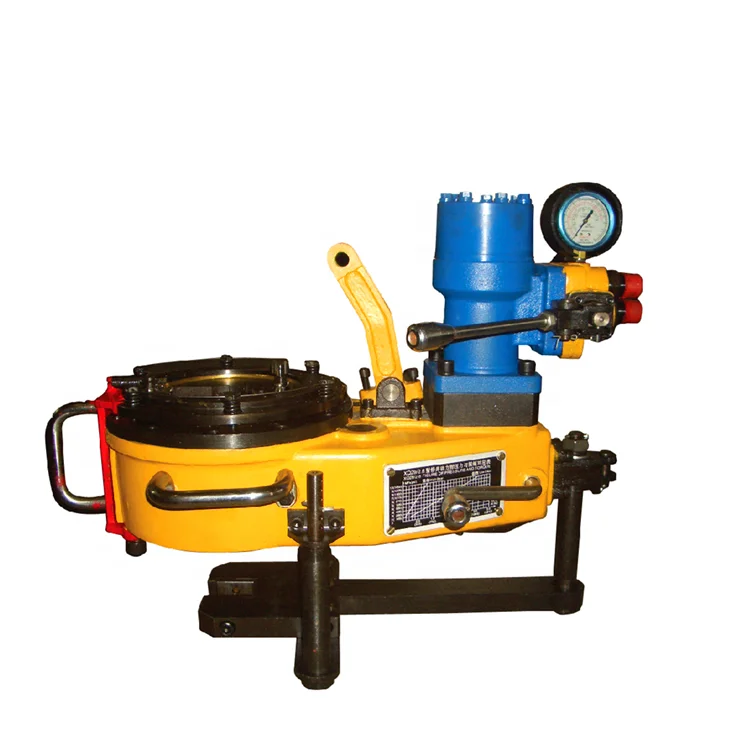
●The structure is compact ,concise and light. Master tong is driven by low speed large torque hydraulic motor which matching with manual control valve. The backup tong just like a spanner.
●The operating is briefness and convenience with die. Put the respondence size jaw set into master tong and the respondence size glutting into backup tong , turning the reset knob in correct direction then can make up and break out sucker rod by operating manual control valve. Two speed, snapping at low speed, spinning at high speed.

The working principle of the hydraulic power clamp is that the power of the workover rig is transferred to the hydraulic motor of the hydraulic power clamp through the stroke reducer, and then through two or one deceleration, the opening gear of the clamp head rotates, resulting in high and low rotational speeds, thus driving the pipe tool (drilling tool) to rotate. When the opening gear rotates, the plate frame does not rotate under the braking action of the brake hammer, so that there is a relative motion between the opening gear and the palate plate frame. In this way, the two rollers of the palate plate will climb the slope and force the clamp teeth on the crotch plate to move toward the center of the pipe tool (drilling tool) until they bite the pipe tool (drilling tool), and then drive the pipe tool (drilling tool) to rotate together with the opening gear.

The sucker rod is an important part of the rod oil pumping equipment. The sucker rod is connected to a sucker rod string by the coupling, the upper part is connected to the pumping unit or PCP motor through a polished rod, and the lower part is connected to the plunger of the sucker pump or PCP. Its function is transmitting the reciprocating motion of the horse head suspension point of the ground pumping unit to the down hole pump or transmitting the rotating torque of the PCP motor to the down hole PCP.
HYDRAULIC SUCKER ROD TONG M20, M40, M50, M75 OPERATION AND SERVICE MANUAL Oil Country Manufacturing, Inc. 300 W. Stanley Avenue Ventura, CA 93001 USA TEL: (805) 643 1200 FAX: (805) 643 6832
GENERAL DESCRIPTION ...................................................................................2HYDRAULIC SUCKER ROD TONG ILLUSTRATION................................................3INSTALLATION OF THE HYDRAULIC SUCKER ROD TONG ...................................4SUCKER ROD DISPLACEMENT VALUES (FIGURE 1).............................................5OPERATION OF THE TONG ...............................................................................6-7SAFETY TOOL INSTALLATION AND REMOVAL ....................................................8ILLUSTRATIONS (FIGURES 2 – 8)......................................................................9-10SERVICE AND REPAIR.......................................................................................11TROUBLESHOOTING.........................................................................................12ILLUSTRATIONS (FIGURES 10 – 11) ..................................................................13MAINTENANCE .................................................................................................14HOW TO ORDER PARTS ....................................................................................15ROD TONG ILLUSTRATIONS .............................................................................16-17ROD TONG REPLACEMENT PARTS LIST .............................................................18-21INNER RING TUBING ASSEMBLIES ....................................................................22-23TORQUE CHART AND SPECIFICATIONS GRAPH..................................................24ROD TONG MOTOR AND PIPING RELIEF VALVE OPERATION ..............................25-26RECOMMENDED SPARE PARTS LIST FOR ONE YEAR...........................................27 GENERAL DESCRIPTION
This manual contains instructions on maintenance and operations of Oil CountryManufacturing, Inc. Hydraulic Sucker Rod Tong (Models M-20, M-40, M-50, and M-75). Thetong has a balanced weight distribution that is easily handled by one man. Front or backthrottle handles control both the speed and the direction of the rotation. The safety doorgates provide quick on-off action, eliminating hand latching.
STANDARD HYDRAULIC ROD TONG ASSEMBLIES PART NUMBER DESCRIPTION 27841 STANDARD M20 ROD TONG ASSY 27841-1 STANDARD M40 ROD TONG ASSY 27841-5 STANDARD M50 ROD TONG ASSY 27841-75 STANDARD M75 ROD TONG ASSY
ROD TONG ASSEMBLY WITH RELIEF VALVE OPERATIONS PART DESCRIPTION NUMBER 27841-101 M20 ROD TONG ASSY WITH RELIEF VALVE OPERATIONS 27841-102 M40 ROD TONG ASSY WITH RELIEF VALVE OPERATIONS 27841-103 M50 ROD TONG ASSY WITH RELIEF VALVE OPERATIONS 27841-104 M75 ROD TONG ASSY WITH RELIEF VALVE OPERATIONS 27841-105 M75 ROD TONG ASSY FOR SATELLITE CONTROL BOX 2 HYDRAULIC SUCKER ROD TONGMODELS M-20, M-40, M-50, AND M-75
3 INSTALLATION OF THE HYDRAULIC SUCKER ROD TONG MODELS M-20, M-40, M-50, AND M-751. Suspend the Hydraulic Sucker Rod Tong on a 9/16” wire line from a point high enough to allow the tong to swing easily around the work area. The line may be attached to a fixed eye or over a sheave for additional counterbalance.2. Install hoses with the pressure hose on the right hand side as viewed from the back of the tong. Ensure that couplings are completely engaged and free of debris.3. Check inner ring to ensure proper size, rotation, and installation of inner ring (refer to illustration on page 9 for installation and removal). Check back-up wrench for proper size and to ensure that wrench is supported by back-up support springs.4. Set relief valve (hydraulic pressure) for breakout of sucker rods. Adjust hydraulic pressure control valve to maximum output of 2000 PSI.5. Install safety line to eye on rear of tong, attach opposite end to rig or secure tie down. WARNING: Failure to do so will cause bodily harm.6. Before attempting to make-up sucker rod, it is very important to adjust the hydraulic control valve to minimum pressure setting to avoid damage to coupling by over- torquing. Slowly adjust pressure to reach specified PSI per chart on page 24. Torque must be adjusted for each rod size prior to make-up. The torque gauge on the rod tong is used for reference only. Pressure must be regulated by PSI gauge on well servicing unit or pressure relief valve. To ensure proper make-up of coupling, refer to the sucker rod displacement chart on page
5 OPERATION OF THE TONGThe Hydraulic Sucker Rod Tong can be operated from the left side, right side, or front ofunit. It is recommended to operate the tong from the front position to ensure properalignment of pin and couplings. All functions of this unit are easily controlled by theoperator, using the throttle control (ref. 109 on parts illustration, page 16).
After installation of the inner ring assembly, rotate the jaws to the “open” position. Observethe bottom square on the sucker rod, guide the tong onto the rod so that the back-upwrench easily slides onto the bottom square. This can be achieved by slightly lifting up onthe front of the tong as you guide it onto the sucker rod. The jaws will automatically adjustto grip the top square.
MAKE-UP1. Inspect the power tong to ensure that hydraulic fluid is at operating temperature. This can be accomplished by running the unit continually for a short period of time.2. Ensure that the pressure relief valve is set on minimum output, and adjust to low side of recommended displacement value.3. Make-up first coupling to hand tight position (see Figure 1). Scribe a vertical line on the top and bottom of coupling.4. Back off coupling approximately four (4) turns, positioning the sucker rod tong on the tong. Activate the throttle handle to fully depressed position.5. Remove the tong and measure the displacement. Compare the displacement with A.P.I. displacement recommendations for type and size of coupling to be run. Increase or decrease the tong operating pressure to achieve manufacturer’s recommended displacement.
6CHANGING DIRECTION OF ROTATION1. Checking Rotation Direction: I. The inner ring rotates in the direction indicated on the top and bottom of the inner ring assembly. The side marked “MAKE” is for making up rods. The side marked “BRAKE” is for breaking out rods. The jaw points in the direction that the rods will turn (ref. Figure 6 and 7, page 9).2. Removing the Inner Ring: I. Rotate the tong to close jaws, stopping rotation when the opening of the inner ring lines up with the opening in the tong case (Figure 8 and 9). Slightly reverse rotation in order to free inner ring for removal (approximately 1” turn only). Remove the inner ring using inner ring safety tool. NOTE: Do not reach inside the tong with hands to remove inner ring.3. Replacing the Inner Ring: I. After removing the inner ring, detach the safety tool, turn inner ring over and attach safety tool. II. Rotate tong 180 degrees. III. Carefully align outer gear roller in center of brake drum opening (Figure 8 and 9). Note that the outer gear roller is in the center of both brake drum and opening in the tong case. IV. Install inner ring, aligning opening of inner ring with brake drum opening (Figure 4). V. When inner ring is in place, it has dropped down over the brake drum pins. The top surface should be approximately 1/2” below the top of the frame plate. Pull back on inner ring safety tool to remove.NOTE: THE OPENING OF THE OUTER GEAR MUST POINT IN THE DIRECTION OF “MAKE”WHEN INSTALLING INNER RING FOR MAKE, AND OPPOSITE FOR BRAKE.
4. Indexing Knob: I. Inner ring assemblies are manufactured with an indexing knob on the side (see Figures 6 and 7). The purpose for this is to prevent installing the inner ring upside down or out of time with the outer ring. It also makes it necessary to line up the opening in the tong case, as described.
7 SAFETY TOOL INSTALLATION AND REMOVALThe Oil Country inner ring safety tool is designed to install and remove the rod tong innerring assembly when changing rod sizes. This tool permits alignment of the inner ring andbrake drum to be achieved by actuating the hydraulic controls.
OPERATION:1. Install the safety tool on the inner ring by pushing down firmly until latches are secure on the inner ring (See Figure 2).2. Rotate the tong until the outer ring gear rollers are in the center of the opening in the inner ring.3. Remove inner ring (See Figure 3).4. Firmly hold inner ring on a flat surface and push quickly on the safety tool to release latches.5. Turn the inner ring over to the opposite side and attach the safety tool.6. Rotate the tong 180º to the opposite direction. Install the inner ring (See Figure 4).7. Push or pull the safety tool to release (See Figure 5).8. Rotate the jaws to the open position.
8910 SERVICE AND REPAIRWARNING: DISCONNECT TONG HYDRAULIC HOSES PRIOR TO INSPECTION ORMAINTENANCE. FAILURE TO DO SO CAN RESULT IN INJURY OR LOSS OF LIMBS.
DISCONNECTING HOSES:1. Shut off hydraulic power prior to attempting to disconnect hoses. If pressure cannot be shut off, disconnect pressure side first and return line last. Failure to do so can result in damage to personnel and equipment.2. Servicing Torque Indicator Gauge: I. This torque gauge should be tested periodically. The torque indicator is a closed system and occasionally must be refilled with hydraulic oil to ensure its accuracy. Oil is required when the load cell piston will not hold the back-up wrench away from the bottom cover plate when under a load. When load cell piston is full of fluid, it will protrude about 3/8” from the piston housing. II. To add oil, turn the tong on its side with the fill hole on the high side. Remove filler plug with an allen wrench. Push the load cell piston back until it bottoms out against the seal. Add hydraulic oil. Replace plug.
11 TROUBLESHOOTING: Problem SolutionTong is out of time: A tong is out of time when the brake drum does not line up with the opening on the tong case. If the brake drum is out of alignment, the inner ring assembly cannot be installed properly. To re-align the drum, use a short piece of wood (2” X 4”) or insert two metal punches in the brake drum pinholes and pry around to correct position. Refer to Figures 10 and 11. NOTE: CHECK BRAKE DRUM AND BAND FOR WEA R. REPLACE IF NEEDED.
Tong jumping out of The tong can jump out of time if the brake cover plate becomestime: loose, allowing the break drum to drop down and disengage from the inner ring or the roll pins in the brake drum become worn or are driving too far in the brake drum. The pins should extend 1/2” above the brake drum to allow the inner ring to index.Jaws fail to engage: Failure of the jaws to grip the rods can be caused by an excessively worn brake band, by interference between the jaws and the inner ring or outer gear or both. If there is interference between the jaws and the outer ring, something is probably holding the inner ring too high, causing the jaws to hit or drag the inside top of the outer ring. This can be caused by: ? The brake drum not being positioned against the brake cover plate. ? A brake drum pin sticking up too high. ? The inner ring hinge pin is not spaced correctly in the inner ring, preventing the brake drum pin from engaging correctly.Oil Leaking from An oil weep hole is provided under the frame beneath the motor. ItWeep Hole: prevents the case from filling up with hydraulic oil if the motor shaft seal leaks or blows out. Check motor and seals for excessive wear and replace, as necessary.
1213 MAINTENANCEINSPECTION1. Inspect all throttle linkage for loose pins. Replace as needed.2. Remove inner ring assembly. Check outer ring roller for wear.3. Check outer ring frame rollers for wear by rotating outer ring with pry bar.4. Inspect the bottom of the tong to inspect back-up support springs, door springs, gate bolts, etc.5. Check torque pressure gauge by prying against one side of back-up wrench.6. Inspect spring hanger assembly, check for wear on top and bottom caps. Replace if worn.LUBRICATIONNOTE: OIL COUNTRY ROD TONG IS MANUFACTURED WITH SEALED BEARINGS ANDPACKED WITH SEALED BEARINGS AND GREASE AT THE FACTORY. MOST INTERNALPARTS RECEIVE AMPLE LUBRICATION FROM THE OIL OFF THE SUCKER RODS. DURINGREPAIR AND INSPECTION, THE TONG SHOULD BE PACKED WITH GREASE AND THEWORN BEARINGS SHOULD BE REPLACED.
SAFETY PRECAUTIONSSafety, based on technical skills and years of experience has been carefully built into yourRod Tong. Time, money, and effort have been invested in making your unit a safe product.The dividend you realize from this investment is your own personal safety.It should be remembered, however, that power-driven equipment is only as safe as the manwho is at the controls. Your are urged, as the operator of this equipment, to observed thefollowing rules:1. Operate the tong from the back-up line side only. (Does not apply to front control tongs.)2. Never change a jaw or put hands within the rotating parts of the tong while tongs are connected to hydraulic hoses.3. Never remove or operate the tong without the guard doors in place.4. Do not exceed the maximum pressure for which this system is rated.5. Always use a back-up line for all tong operations.6. Keep loose fitting clothing away from the rotating parts of the tong.
When ordering parts for your Rod Tong, refer to the following Parts List. Use schematicdrawing to locate the correct item number, and then obtain part number.
151617 ROD TONG REPLACEMENT PARTS LISTREF. PART NO. WGTNO. NUMBER REQ DESCRIPTION LBS 27841 M20 Rod Tong Assembly 27841-1 M40 Rod Tong Assembly 27841-5 M50 Rod Tong Assembly 27841-75 M75 Rod Tong Assembly 27841-101 M20 Rod Tong Assembly With Relief Valve 27841-102 M40 Rod Tong Assembly With Relief Valve 27841-103 M50 Rod Tong Assembly With Relief Valve 27841-104 M75 Rod Tong Assembly With Relief Valve 27842 Frame Assembly1 27862 1 Frame 26.002 27868 2 Outer Ring Wear Ring 1.253 27869 4 Idler Gear Thrust Washer .504 27870 1 Cluster Gear Shaft .755 27871 2 Second Reduction Washer .256 27872 2 Cluster Gear Thrust Washer .507 27873 14 Thrust Washer Retainer Pin .069 942392-112 1 2nd Reduction Gear Lower Needle Bearing .3010 27851-1 1 2nd Reduction Gear 13.6311 942392-53 4 Idler Gear Shaft Bearing .3011A 29888 2 Idler Gear Shaft Disc .1311B 992253-137 2 Idler Gear Shaft Disc Snap Ring .2512 940287-819 1 2nd Reduction Gear Shaft Seal .1013 940287-12 4 Idler Gear Shaft Lower Seal .1014 944524-244 1 Motor Pinion Retaining Ring .1015 992082-74 3 Frame to Cover Dowel .2517 944524-295 1 Motor Pinion Retaining Ring .10 27850 1 Motor Pinion Assy (ref. 18-21) (M-20 and M-40) 3.00 28614 1 Motor Pinion Assy (ref. 18-21) (M-50 & M-75) 3.0018 27921 1 Motor Pinion Gear (M-20 and M-40) .1318 29197 1 Motor Pinion Gear (M-20 and M-75) 1.5019 979384-8 1 Motor Pinion Lower Bearing 1.0020 979384-10 1 Motor Pinion Upper Bearing (M-20 and M-40) .2520 28610 1 Motor Pinion Bearing Adapter Ring (M-50 & M-75) .38 27847 1 Cluster Gear Assy (ref. 22 and 23 (M-20 and M-40) 7.00 28613 1 Cluster Gear Assy (ref. 22 and 23 (M-50 & M-75) 7.0022 27922 1 Cluster Gear (M-20 and M-40) 6.1322 29196 1 Cluster Gear (M-50 only) 6.5023 942392-72 1 Cluster Gear Bearing .25 27846 2 Idler Gear Assy 5.1324 27866 2 Idler Gear 5.1325 27867 2 Idler Gear Shaft .75 30026 1 Outer Ring Assy (ref. 26-29) 21.1326 30026-01 1 Outer Ring Gear 19.1327 30027 2 Outer Ring Roller .6327 30027-75 2 Outer Ring Roller (M-75) .6028 30028 2 Outer Ring Roller Pin .25 18 ROD TONG REPLACEMENT PARTS LISTREF. PART NO. WGTNO. NUMBER REQ DESCRIPTION LBS 27843 1 Frame Cover Assy (ref. 30-45)29 992081-04 2 Outer Ring Plug .1330 27874 1 Frame Cover 12.0032 942453-11 14 Outer Ring Roller Frame 1.0033 992116-10 14 Outer Ring Frame Roller Nut .3038 942393-84 1 2nd Reducing Gear Needle Bearing .3039 940286-318 1 2nd Reducing Gear Upper Seal .1040 944047-08 2 Frame Cover Snap-In Seal .9041 992019-17 3 Frame Cover Cap screw .2043 992019-10 2 Frame Cover Cap screw .2044 992019-20 3 Frame Cover Cap screw .2045 992015-06 2 Frame Cover Outer Wear Ring Cap screw .20 27844 Gear Case Cover Assy 11.5047 27875 1 Gear Case Cover 11.0048 27876 1 Back-Up Wrench Support Spring .2549 28007 1 Support Spring Plate 1.0050 992003-03 2 Support Spring Cap screw .4051 27877 1 Back-Up Wrench Pivot Spring .5052 27878 1 Pivot Spring .7553 992019-07 1 Pivot Spring Cap screw .2053A 992164-05 1 Nut .1053B 992051-06 1 Lock Washer .1054 27909 1 Pivot Spring Retainer Plate .3855 27908 1 Torque Indicator Load Cell Piston .1359 992154-212 1 Load Cell Piston O-Ring .1060 992287-SC-212 2 Load Cell Back-Up Ring .1061 940288-471 1 Piston Seal .1062 992080-02 1 Load Cell Pipe Plug .2563 27918 1 Gasket-Gear Box Cover .1364 992019-06 11 Gear Case Cover Cap screw .2065 992160-08 11 Lock Washer .10 27852 Hanger Assy (ref. 71-77) 6.0071 27852-1 1 Hanger 3.2572 45019 1 Hanger Balancing Screw 2.0074 992586-40 1 Hanger Balancing Screw Bolt .0774A 992162-09 1 Hanger Balancing Screw Nut .2074B 992587-16 1 Hanger Balancing Screw Washer .2577 992003-06 4 Hanger Cap screw .2578 27848-200 1 Brake Drum Assy (includes 78A pins) 2.7578A 27884 2 Brake Drum Pin (Was 992011-198) .0679 27849-200 1 Brake Band 5.0080 27861-2 1 Brake Band Anchor Pin Kit81 992155-02 1 Flat Washer .1083 27855 1 Brake Cover Plate 1.0084 992015-09 2 Brake Cover Plate Cap screw .20 19 ROD TONG REPLACEMENT PARTS LISTREF PART NO WGTNO NUMBER REQ DESCRIPTION LBS 27899 1 Inner Ring Assy, 5/8”, 3/4”, and 7/8” Rods With 1”Flats (ref. 85-89) 6.5085 27894 1 Inner Ring 5.0086 27900 2 Jaw, 5/8”, 3/4”, 7/ 8” Plain For 1” Flats 5.0088 27897 2 Jaw Spring 1.0089 27722 2 Jaw Hinge Pin .2590 27902 1 Back-Up Wrench, 5/8” Rod 10.0090 27903 1 Back-Up Wrench, 3/4” - 7/8” Rod 10.00 27899-3 1 Inner Ring Assy, 7/8” EL Rods with 1-1/8” Flats (ref 85-89) 6.5085 27894 1 Inner Ring (ref. 85-89) 5.0086 27900-1 1 7/8” EL Jaw For 1 1/8” Flats 5.0088 27897 2 Spring 1.0089 27722 2 Latch Pin .2590 27903-1 1 Back-Up Wrench, 7/8” EL Rod 10.00 27899-4 1 Inner Ring Assy, 1” Rods W/ 1.312” Flats (ref. 85-89) 6.5085 27894 1 Inner Ring 5.0086 32967 1 Jaw 1” For 1.312 Flats 1.3888 27897 2 Spring 1.0089 27722 2 Latch Pin .2590 27906 1 Back-Up Wrench, 1” Rod 10.00 27899-1 1 Inner Ring Assy, 1-1/8” Rod W/ 1.500 Flats (ref. 85-89) 6.5085 27894 1 Inner Ring 5.0086 27905 1 Jaw 1-1/8” For 1.500” Flats .1388 27897 2 Spring 1.0089 27722 2 Latch Pin .25 27899-6 1 M-75 Inner Ring Assy, 1-1/8” Rod W/ 1.500 Flats (ref. 85-89) 6.5085 27894 1 Inner Ring 5.0086 27975 1 Jaw 1-1/8” (M-75) For 1.500 Flats 1.3888 27897 2 Spring 1.0089 27722 2 Latch Pin .2590 27906 1 Back-Up Wrench, 1” Rod 10.0090 27907 1 Back-Up Wrench, 1-1/8” Rod 10.0099 992154- 1 Frame Torque Indicator O-Ring .10 110100 27860 1 Frame Handle .13101 992501-11 6 Frame Cover Nut .20102 29783 1 Control Valve Shaft .50103 29143 1 Torque Indicator Gauge 4.00 29192 1 Front End Control Assy (ref. 104-113) 4.00
ITEM PART NO. QTY DESCRIPTION------- 27880-201 1 RELIEF VALVE MOTOR & PIPING GROUP W/ M20 ROD TONG (ITEMS 1-16)------- 27880-200 1 RELIEF VALVE MOTOR & PIPING GROUP W/ M40 ROD TONG (ITEMS 1-16)------- 27880-202 1 RELIEF VALVE MOTOR & PIPING GROUP W/ M50 ROD TONG (ITEMS 1-16)------- 27880-203 1 RELIEF VALVE MOTOR & PIPING GROUP W/ M75 ROD TONG (ITEMS 1-16)1 27841-M20 1 TORQUE INDICATOR PLATE: M20 ROD TONG1 27841-M40 1 TORQUE INDICATOR PLATE: M40 ROD TONG1 27841-M50 1 TORQUE INDICATOR PLATE: M50 ROD TONG1 27841-M75 1 TORQUE INDICATOR PLATE: M75 ROD TONG2 27883-200 1 ROD TONG GAUGE HOUSING: WELDMENT3 30020-200 1 M20/ M50 ROD TONG HYDRAULIC MOTOR F/ RV: SUBASSY3 30021-200 1 M40/M75 ROD TONG HYDRAULIC MOTOR F/ RV: SUBASSY4 700B-04-019-02 1 HYDRAULIC HOSE 5 700B-08-019-02 1 HYDRAULIC HOSE6 943972-46 1 RELIEF VALVE7 992080-03 1 DRYSL PRESSURE PLUG8 992081-06 1 FLSHSL PRESSURE PLUG9 992131-S-12-12 1 NPT HEX NIPPLE ADAPTER:10 992131-S-16-12 1 NPT HEX NIPPLE ADAPTER11 992141-S-12-8 2 FL 90 ADAPTER12 992151-S-16-16 1 RUN TEE ADAPTER13 992171-01 1 3000 PSI/ BAR GAUGE14 992204-04 3 FILLISTER HEAD SCREW15 992344-S-04-04 1 90° ADAPTER16 992475-S-04-04 1 90 FL ADAPTER*17 992285-FH-16-16 FEMALE QUICK DISCONNECT (AEROQUIP)*18 992285-MH-16-16 MALE QUICK DISCONNECT (AREOQUIP)*19 45407-203 2 SWIVEL JOINT*NOTE: THESE COMPONENTS NOT INCLUDED WITH ASSEMBLIES
PART NO. DESCRIPTION QTY.27849-200 Brake Band 2 27861-2 Brake Band Anchor Kit 4 27884 Brake Drum 1942453-11 Cam Followers 14 27876 Backup Wrench Support Spring 1 27858 Gate Spring 1 30027 Outer Ring Roller 2 27897 Rod Jaw Spring 6992011-58 Gate Roll Pin 2
PART NO. DESCRIPTION QTY.27849-200 Brake Band 4 27861-2 Brake Band Anchor Kit 8 27884 Brake Drum 2942453-11 Cam Followers 28 27876 Backup Wrench Support Spring 2 27858 Gate Spring 2 30027 Outer Ring Roller 4 27897 Rod Jaw Spring 12992011-58 Gate Roll Pin 4 27868 Wear Ring 2 27878 Pivot Pin 2 30028 Outer Ring Roller Pin 2992011-58 Gate Roller in 6

Power Tongs are used for running or pulling tubular strings during well repair, workover, snubbing, drilling and casing operations to extract oil and gas from wells.


 8613371530291