
weatherford lamb power tong supplier

The 14-100 hydraulic power tong provides 100,000 ft-lb (135,600 N∙m) of torque capacity for running and pulling 7- to 14-in. casing. The tong has a unique gated rotary, a free-floating backup, and a hydraulic door interlock.
Our 14-50 high-torque casing tong provides 50,000 ft-lb (67,790 N∙m) of torque capacity for running and pulling 6 5/8- to 14-in. casing. The tong has a unique gated rotary, a free floating backup, and a hydraulic door interlock.
The 16-25 hydraulic casing tong provides 25,000 ft-lb (33,900 N∙m) of torque capacity for running and pulling 6 5/8- to 16-in. casing. The tong features a unique gated rotary and as many as seven contact points that create a positive grip without damaging the casing.
Rigged up without rig modifications, our 21-300 riser tong is the only tong capable of producing 300,000 ft-lb (406,746 N∙m) of continuous rotational torque in both makeup and breakout mode. The power it achieves in a compact size compares with a conventional 24-in. casing tong.
The 24-50 high-torque casing tong provides 50,000 ft-lb (67,790 N∙m) of torque capacity for running and pulling 10 3/4- to 24-in. casing. The tong features a unique gated rotary, a free-floating backup, and a hydraulic door interlock.
The 30-100 high-torque casing tong provides 100,000 ft-lb (135,600 N∙m) of torque capacity for running and pulling 16- to 30-in. casing. The tong features a unique gated rotary, a free-floating backup, and a hydraulic door interlock.
The 5.5-15 hydraulic tubing tong provides 15,000 ft-lb (20,340 N∙m) of torque capability for makeup and breakout of 1.66- to 5.5-in. tubing and premium or standard connections on corrosion‑resistant alloy tubulars. The tong features an ergonomic, lightweight design with a free-floating hydraulic backup.
The 7.6-30 hydraulic tubing tong provides 30,000 ft-lb (40,670 N∙m) of torque capability for makeup and breakout of 2 3/8- to 7 5/8-in. tubing and premium or standard connections on corrosion‑resistant alloy tubulars. The tong features an ergonomic, lightweight design with a free-floating hydraulic backup.
Our SpeedTork 8.0-70 tong provides torques up to 70,000 ft-lb (94,900 N∙m) and 360° rotation in makeup and breakout operations. It can torque drillpipe connections, drillstring components, drilling tools, packers, couplings, and valves.
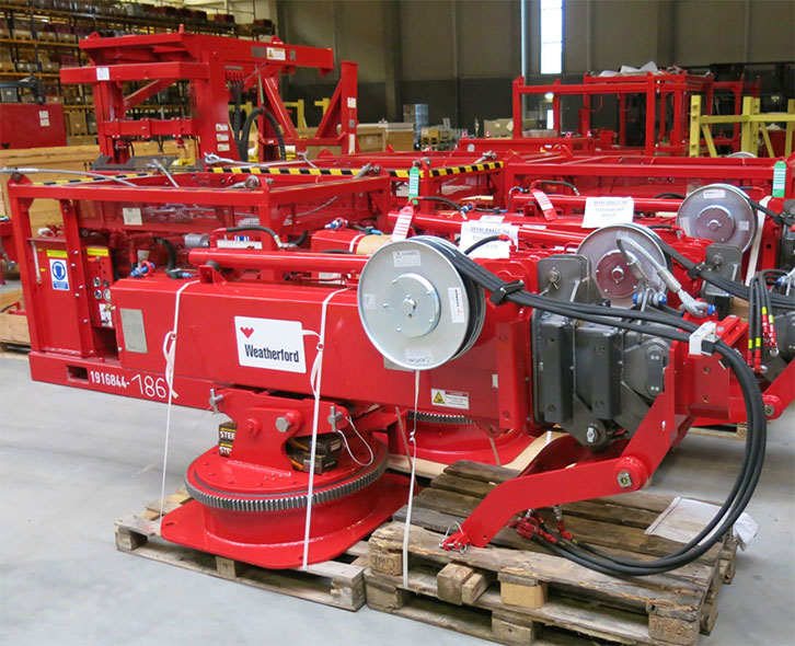
Weatherford is the leading wellbore and production solutions company, providing integrated solutions across well stages and customer domains to the oil and gas industry.
Manufacturer of oil well casing hydraulic power tongs. Provides make-up and break-out capabilities when running casing tubular in the drill hole. Available from 5 1/2 to 36 in. capacity and 15,000 up to 2,00,000 ft·lb torque. Offered with self aligning throat, speed shifting and radial lock door. Suitable for handling high torque and lightweight casing. Secondary services include assembly, engineering, welding, cutting, heat treating, machining, testing and inspection. Serves oil and gas industries. CE certified. Made in the USA.
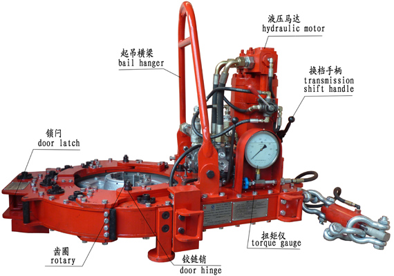
The tongs head of oscillating double jaw plate is made by precision casting, in this way, not only the outline is beautiful, but also the strength is high and the dismounting is convenient. The perfect design can ensure that the clamping is reliable and the backslide is easy.It adopts ribbon brake apparatus, and the brake moment is high. The operation is so easy that it’s convenient to repair and change.With hydraulic torque indicator and installation interface of torque gauge, it can equip model NKY torque control recorder, so as to realize the computer management.
This invention is directed to apparatus and methods for aligning wellbore tubulars; and to power tongs used in making and breaking joints of tubular members such as wellbore casing and tubing; to parts thereof; including, but not limited to gripping elements, and methods of their use.
During the drilling of oil and gas wells and the production of materials therefrom, various operations require the connection and disconnection of successive lengths of threaded tubulars such as pipe, casing, or tubing. Tools known as tongs are used to "make" and "break" such connections. Certain known power tongs have a body, a rotary rotatably mounted in said body and at least one active jaw which, on rotation of the rotary is cammed against a pipe in the rotary and grips it for rotation with the rotary. In known arrangements the camming action is generated by a cam member which is bolted to the rotary and is shaped so that the active jaw is cammed against the pipe on rotation of the rotary relative to the active jaw in one sense and will be released on rotation of the rotary relative to the active jaw in the opposite sense.
With known tongs high torques are applied to tubulars due to combinations of factors such as thread sealing requirements, the presence of corrosion, the existence of distortion, and pipe size and weight. Both in the "make" direction of rotation when a shoulder is suddenly encountered, and in the "break" direction at initial engagement of the tong and disengagement of the threads high shock forces may arise; e.g., with a power-driven tong, in excess of 50,000 foot-pounds of torque may be exerted, while relatively small die elements on jaws of the tong engage the pipe with extremely high force loadings. Slippage occurs and pipe surfaces become marred, marked, indented, or otherwise damaged.
Dies for gripping jaws have been provided with multiple serrations, or penetration features, to provide the interference contact at the joint surface. Grip element penetration into the joint surface is limited and controlled. The distribution and balance of grip element energizing forces are critical factors in the design, development and evaluation of such tong mechanisms. Linkages, levers, wedges, and cams are used to balance force components. Grip elements, or dies, are accurately disposed within carrier bodies, or jaws, which span a circumferential segment of the joint surface.
Uneven die loading can cause excessive indentation, marring or damage to a tubular surface. Drag or braking devices are used in certain tongs to effect proper biting of the dies relative to the pipe. The head or other member supporting the dies is frictionally restrained to insure that the dies do not simply rotate with the rotary as the rotary is driven.
Other tongs use an endless belt, chain or flexible material loop for gripping a tubular. Such tongs are disclosed in U.S. Pat. Nos. 3,799,010; 3,906,820; 3,892,140; 4,079,640; 4,099,479; and 4,212,212. There are a variety of problems associated with certain of these tongs:
Jaw/die tongs and the belt/chain tongs are used with relatively hard and rigid metal tubulars such as casing and tubing. If these tongs are used with thick tubulars or tubulars made from relatively "softer" metals or from premium metals such as high alloy steels or low carbon steels or tubulars made from non-metal materials such as fiber glass, they often literally chew up the tubular. The use of strap wrenches is inadequate since the torque applied with such wrenches cannot be precisely controlled.
Certain tubulars are treated with a rust or corrosion resistant material or coating. If the coating is indented, gouged, or broken, its protective purpose is defeated. Producing enough force in a tong to join such tubulars while not injuring a protective coating presents a dilemma.
The present invention, in certain embodiments, discloses a power tong for joining tubulars so that marking of, indentation of, and surface injury to tubulars are reduced or eliminated. In one aspect a power tong is provided and a method of its use for handling tubulars coated with a corrosion-resistant material which should not be broken or penetrated. In one embodiment such a tong has one or more gripping jaws with gripping elements made of aluminum alloys, zinc, zinc alloys, aluminum, brass, bronze, cermet, plastic, fiberglass, metal alloys, or a combination thereof which present a smooth face (straight or curved) to a tubular without any teeth, pointed projections, or toothed dies. In one aspect the gripping elements are releasably connected directly to jaws. In another aspect the gripping elements are releasably connected to a jacket or holder which itself is releasably connected to a jaw.
In one aspect the cylinder(s) are powered by a small air-driven hydraulic pump with an hydraulic fluid reservoir mounted on a plate on the movable or fixed jaw. Air is supplied to activate a motor of the pump and the pump then provides hydraulic fluid to move a piston of the hydraulic cylinder(s). The motion of the cylinder moves the movable jaw on its roller to travel to a pre-load position on the cam. The cylinder applies pressure until the hydraulic pressure is released. A hydraulic fluid accumulator and a valve may be used to maintain hydraulic pressure at all times so that the cylinder(s) continuously maintain the desired load on the jaw until the air supply to the pump is removed.
In another aspect the cylinders are connected to a rotary of the tong or to any other member that rotates with the rotary rather than to a fixed jaw. Such a pre-load system may, according to this invention, be used with any tong including a tong that does use toothed dies.
In one embodiment the present invention discloses a gripping arrangement for a tong with a sheet of grit which is preferably bonded to a carrier plate. In another embodiment the gripping arrangement comprises a layer of flexible material having a smooth flat surface or a surface with ridges and valleys, for example in the fashion of the surface of a file. The flexible material, in one aspect, is metal, for example sheet aluminum, zinc, brass, bronze, zinc alloy, aluminum alloy, stainless steel, or steel having a thickness of about 1.5 mm. The layer of flexible material may be used in conjunction with a carrier plate or on its own. In a further embodiment the gripping arrangement may comprise a layer of perforate material one of both surfaces of which are preferably coated with grit to facilitate adhesion. The layer will typically be formed from metal having a thickness of about 1.5 mm. The layer may be used in conjunction with a carrier plate or used on its own. In yet another embodiment the gripping arrangement may comprise a layer of expanded mesh, e.g. metal mesh, which has been flattened. One or both surfaces of the expanded mesh may be coated with grit and the layer may be used in conjunction with a carrier plate or used on its own. The grit may comprise, for example, diamond dust, particles of silicon, zircon, tungsten carbide and mixtures thereof. The gripping arrangement may comprise end plates which are attached to the carrier plate. Preferably, the carrier plate is provided with side flanges for insertion into a jaw holder. The present invention also provides a jaw assembly fitted with a gripping arrangement in accordance with the present invention. Preferably, the jaw assembly includes a jaw holder having an arcuate recess which accommodates an arcuate pad of resilient elastomeric material which supports said gripping arrangement. Advantageously, at least one shim is provided which is disposed between said arcuate pad of resilient elastomeric material and said gripping arrangement. The shim will be flexible and generally from 0.5 mm to 1.0 mm thick and made from sheet metal. The present invention also provides a tong fitted with at least two such jaw.
In one embodiment the present invention discloses an apparatus for aligning tubulars and includes a guide on one of a power tong and a backup tong. In one embodiment the apparatus has a socket centralizer mounted on said one of said power tong and said backup tong. In one aspect, said one of said power tong and said backup tong is said power tong. In another embodiment, the apparatus includes a power tong and a backup tong, and the guide is mounted on the power tong and apparatus is provided to maintain the power tong and the backup tong in a certain juxtaposition during a stabbing operation. Preferably, said apparatus includes locating rods on one of the power tong and the backup tong and blocks shaped to receive at least the ends of the locating rods on the other of the power tong and the backup tong. Advantageously, the backup tong is provided with at least two prismatic jaw assemblies to locate the backup tong in fixed juxtaposition with respect to a tubular being gripped.
The present invention, in one aspect, provides a jaw unit for use in a tong, which jaw unit comprises a jaw holder and a jaw movable with respect to said jaw holder, characterized in that said jaw is slidably mounted on said jaw holder. Preferably, said jaw is slidable with respect to said jaw holder about an arcuate path. Advantageously, said jaw has a gripping surface which is substantially arcuate for gripping the surface of a tubular and the center of curvature of such arcuate path lies between the center of curvature of said grip ping surface and said arcuate path. The gripping surface may be a continuous surface or defined by several spaced apart gripping elements. Preferably, the center of curvature of said arcuate path lies between the center of curvature of said grip ping surface and said gripping surface. Advantageously, the center of curvature of said arcuate path is substantially midway between the center of curvature of said gripping surface and said gripping surface. Preferably, one of said jaw and said jaw holder is provided with an arcuate track which defines said arcuate path, and the other of said jaw and said jaw holder is slidably mounted in said arcuate track.
The present invention also provides a jaw assembly comprising two jaw units in accordance with the present invention. Preferably, said jaw units are mounted for pivotal movement about a common pivot shaft. Advantageously, said jaw assembly includes means which bias said jaw units apart. The present invention also provides a rotary fitted with a jaw unit in accordance with the present invention, a rotary fitted with a jaw assembly in accordance with the present invention, and a tong fitted with a rotary in accordance with the present invention.
One of the features of existing tongs is that their rotaries are difficult to furnish. Thus, routine maintenance usually involves dismantling the whole rotary, checking the parts and reassembling the whole. While this is a straightforward procedure in the clean conditions of a workshop it can be problematic when carried out in a muddy field, in sand or in snow. The present invention aims to help solve this problem and provides a rotary which comprises a top section, a bottom section, and a peripheral wall therebetween, characterized in that at least one of said top section and said bottom section is provided with an elongate slot which, when said rotary is in use, accommodates a pivot shaft on which a jaw assembly can be pivotally mounted.
Jaw holders and jaws for tongs are traditionally machined from a solid piece. This is a comparatively expensive procedure. The present invention proposes to make such parts from a stack of individually cut laminations.
Such methods and devices including a power tong with at least one jaw with at least one tubular gripping element having a smooth gripping surface (flat or curved) and, in one aspect, such an element which is flexible;
FIG. 2A is a perspective view of a tubular connection system according to the present invention. FIGS. 2B and 2C are perspective views of a casing tong of the system of FIG. 2A.
FIG. 5A shows schematically an initial position of elements of a tong system according to the present invention. FIG. 5B shows pre-loading on a pipe of the jaws of the system of FIG. 5A. FIG. 5C shows a tubular gripped with the system of FIG. 5A.
FIGS. 1A-1C show a typical prior art power tong that uses fixed jaws and a movable jaw to grip pipe for tubular disconnecting and connecting operations. An outer case houses a powered rotary to which the jaws are mounted. A cam surface of the rotary moves a movable (ACTIVE or MASTER) jaw into (and away from) gripping contact with a tubular, e.g. pipe. Each jaw has toothed gripping inserts to facilitate engagement with the surface of the tubular (see FIG. 1B). FIG. 1C shows the tong in an "OPEN" position in which the tubular is not gripped.
The tong shown in FIG. 1A is a Weatherford Model 14.5-50 High Torque Tong. The brochure "New ! Weatherford Model 14.5-50 High Torque Tong," (1991) and the manual entitled "Model 14.5-50 Hydraulic Power Tong Installation, Operation and Maintenance" (1993) are submitted herewith and incorporated herein fully by reference for all purposes. It is to be understood that the teachings of the present invention are applicable to any tong and any tong system that has one or more gripping elements or jaws and that the Model 14.5-50 tong is shown here for illustrative purposes and not by way of limitation of the scope of the present invention.
As shown in FIG. 2A a system 10 according to the present invention includes a power tong 100 according to the present invention which is like the tong of FIG. 1A but which also includes a unique jaw system 110 with inserts 150 on fixed jaws 120 and insert 152 on movable jaw 122 and at least one jaw pre-load assembly like that shown in FIG. 5A. The system 10 includes a free floating backup tong 12.
As shown in FIGS. 2B and 2C, rods 112 are connected to the movable jaw 122. The inserts 150 are on fixed jaws 120 and the insert 152 is on a movable jaw 122 (corresponding to the fixed jaws and active jaw, respectively, of the tong of FIG. 1A).
FIGS. 4A-4G illustrate an alternative jaw mounting system in which holders are interposed between jaw bodies and inserts. The holders protect the jaws from damage if the inserts wear down and a variety of different types and/or sizes of inserts may be used with and interchanged on a single holder. In one aspect it is within the scope of this invention to use these holders to mount conventional toothed dies to a tong jaw and to use them for easy substitution of new and/or different dies.
FIG. 4A shows a jaw system 400 for a tong (like the tong of FIG. 2A) which has two fixed jaws 402 and a movable (movable toward and away from a tubular to be gripped 403) jaw 404. Each jaw 402 has a jaw body 405 with a holder 406 secured thereto. In one aspect dovetail keys 407 secured to the holder or releasably mounted thereto fit in corresponding slots 408 of the jaw bodies 405 to releasably mount the holder 406 to the body. In one aspect dovetail keys 409 releasably mount the holders 406 to jaw bodies 405. The dovetail keys 409 are releasably held in corresponding recesses 411 in the holders 406. One or more dovetail keys 409 may be used (two shown for each holder 406).
FIG. 5A shows a tong system 500 with a tong having a movable rotary 502, fixed jaws 504, 505, and a movable jaw 506 (remainder of tong, not shown, like the tong of FIG. 2A; like the tong of FIG. 1A, but with the added features discussed here). Pins 520 pin the fixed jaws to the rotary. Inserts 522 on the fixed jaws 504, 505 are like the inserts described herein for other fixed jaws. Insert 524 on the movable jaw 506 is like other inserts described herein for movable jaws. A pre-load cylinder 508 to assist in make-up is pivotably connected at one end to the fixed jaw 505 and at the other end to the movable jaw 506. A pre-load cylinder 510 to assist in break-out is pivotably connected at one end to the fixed jaw 504 and at the other end to the movable jaw 506. It is within the scope of this invention for the ends of cylinders connected to the fixed jaws to instead be secured to the rotary or to a support ring or other member that rotates with the rotary. It is within the scope of this invention to employ one cylinder interchangeable between the positions of the cylinders 508 and 510 (FIG. 5A) or one cylinder connectible to the fixed jaw 506 at one end for break-out and at the other end of the fixed jaw 506 for make-up with the other cylinder end secured to the rotary. Rollers 530 rotatably mounted on the movable jaw 506 co-act with cam surfaces 532 on the rotary 502 to move the jaw 506 to operative and inoperative positions.
Air in a line 640 selectively applied with a control system 650 (e.g. mounted on the rig floor, on the tong or remote controlled) selectively actuates the pump 630 to pump fluid through the valve 602 to the pre-load cylinders. The directional control valve 602 is either manually operated or operated by remote control. Correct fluid pressure is monitored with a gauge 651.
As shown in FIG. 5C the tubular 650 has been gripped due to the action of the pre-load cylinder 510 with a suitable pre-load force (e.g., but not limited to, about 500, 1000, 5000, 10000 or 50000 pounds of force). This force is sufficient that when the rotary 502 of the tong is rotated the jaws do not slip on the tubular 650; but the pre-load force is sufficiently low that the jaws do not mark or damage the tubular 650.
FIG. 8 shows schematically a top view of a power tong according to the present invention. A power tong T has an hydraulic motor M with control/monitor apparatus C on a tong case S. A movable jaw J is moved and rotated by a rotary R which is moved by interconnection, via appropriate gearing, by the motor M. Fixed jaws F and G are secured to the rotary R. A first pre-load cylinder D connects the movable jaw J to the fixed jaw G for applying a pre-load to the movable jaw for make-up operations. A second pre-load cylinder L connects the movable jaw J to the fixed jaw F for applying a pre-load to the movable jaw for break-out operations. An insert I (any insert disclosed herein) is secured to the movable jaw J and inserts K (any insert disclosed herein) are secured to the fixed jaws F and G.
FIG. 9 shows a tong jaw 450 according to the present invention with an insert 454 (any insert disclosed herein) and rods 452 secured thereto, e.g. by welding. The rods 452 provide a member to which either a cylinder body or a piston of a pre-load piston cylinder apparatus is connectible. Instead of the rods 452 as shown which extend from above the jaw 450 to a point below it, only rod sections may be used secured to one or both sides of the jaw to provide a securement member for an end of a pre-load apparatus.
According to the present invention a variety of apparatuses and devices may be employed to pre-load a tong jaw having one or more smooth faced gripping insert elements thereon. In one aspect a manually activated pre-load cylinder is used which has fluid or material manually introduced therein to apply a pre-load or manually removed therefrom to release a pre-load. In another aspect a pre-load cylinder is pivotably secured at one end to a rotary or part thereof and the other end is releasably connectible to either end of a movable jaw so that a pre-load may be applied, selectively, to either end of the movable jaw for make-up or break-out operations as desired. In one aspect such a pre-load cylinder has a rod with an end member receivable in and movable in a slot in the movable jaw or there are recesses at either end of the jaw for holding the end member of the rod so that a pre-load can be applied. A secondary small cylinder may be used to selectively move the pre-load cylinder in the jaw slot or it can be moved manually. In another embodiment the tong"s movable jaw has one or more upwardly projecting lugs engageable by a forked piston rod end of a pre-load piston/cylinder that is attached to the rotary. The rotary is rotated so that the jaw is cammed into the pipe to be rotated in a pre-load position and then the forked rod is removed for further tong operations.
In use, two or more jaw assemblies are placed in a tong and are disposed around a length of casing. The jaw assemblies 1001, 1001" are then advanced radially inwardly in the direction of arrows "A" (FIG. 12) until they engage and firmly grip the casing. Because of the flexible construction of the gripping arrangement 1007, the shims 1006 and the arcuate pad 1004, the friction layer 1009 substantially conforms to the circumference of the casing and grips the casing with a substantially uniform gripping action. Once the casing has been firmly gripped the jaws are rotated by the tong in the usual manner. It will be noted that circumferential forces applied to the friction layer are transmitted through the carrier plate 1008 so that any local loads caused, for example by an irregularity in the surface of the casing are redistributed by the carrier plate 1008 and transmitted to the jaw holder 1002 via the side flange 1011 and the arcuate pad 1004 (see FIG. 18).
Referring to FIGS. 19A and 19B of the drawings there is shown a conventional tong assembly which is generally identified by the reference numeral 2001.
The power tong 2002 comprises a pair of gates 2004, 2005 which are held together in the position shown by latch 2006. When the latch 2006 is released the gates 2004, 2005 can be swung open by admitting hydraulic fluid to piston and cylinder assemblies 2007 and 2008. The power tong 2002 also contains a rotary 2009 which is provided with four jaw assemblies 2010. The rotary 2009 can be rotated by a hydraulic motor 2011.
The backup tong 2003 is provided with two gates 2012, 2013 which are held together by latch 2014 but which, when latch 2014 is released can be swung to an open position.
Once the pin is correctly located the stabbing guide is removed. The gates 2004, 2005 of the power tong 2002 and the gates 2012, 2013 of the backup tong 3 are then opened and the tong assembly 2001 moved towards the casing until the lower length of casing lies within the backup tong 2003 and the upper length of casing lies within the power tong 2002. The gates 2004, 2005, 2012, 2013 are then closed and latched. Jaw assemblies in the backup tong are then advanced to engage the lower length of casing while jaw assemblies in the power tong 2002 are advanced to grip the upper length of casing. The hydraulic motor 2011 is then actuated to turn the rotary 2009 and rotate the upper length of casing relative to the lower length of casing. The tong assembly 2001 is supported by a pneumatic lifting cylinder 2015 which enables the power tong 2002 to move towards the backup tong 2003 as the pin enters the socket. Reaction forces are transmitted by columns 2016 disposed to either side of the tong assembly 2001 and by a series of levers in a known manner. It should be noted that the power tong 2002 is free to move in a plane parallel to the backup tong 2003 within certain limits.
The apparatus 2100 comprises a tong assembly 2101 which is generally similar to the tong assembly 2001 shown in FIGS. 19A and 19B and parts of the tong assembly 2101 similar to the tong assembly 2001 have been identified by similar reference numerals in the "2100" series.
Turning first to the guide 2117 it will be seen from FIG. 21B that this comprises four identical components 2118 which are bolted to the top of the power tong 2102. As best shown in FIG. 21C each component is tapered so as to guide the pin of an upper casing to the center of the opening of the power tong 2102.
Referring now to FIG. 22, the backup tong 2103 is provided with three prismatic jaw assemblies 2119a, 2119b, and 2119c which, when actuated, hold a lower length of casing 2120 in a fixed position relative to the backup tong 2103.
As shown in FIG. 23 the backup tong 2103 is provided with three upwardly extending locating rods 2121 which are each provided with a conical tip 2122. Similar, the underside of the power tong 2102 is provided with three blocks 2123 each of which is provided with a recess 2124 shaped to receive the conical tip 2122 of a respective locating rod 2121.
In use, the lower length of casing 2120 is first secured by slips on the rig floor in the usual manner. The gates 2112 and 2113 of the backup tong 2103 are then opened and the tong assembly 2101 moved into position with the backup tong 2103 circumjacent the lower length of casing 2120 and immediately below the socket 2125 thereof.
The gates 2112 and 2113 are then closed by hydraulic piston and cylinder assemblies 2126 and 2127 and the latch 2114 closed. The prismatic jaw assembly 2119a is fixed while prismatic jaw assemblies 2119b and 2119c are automatically advanced by a predetermined distance when the latch 2114 is closed. This grips the lower length of casing firmly and also ensures that the backup tong 2003 is in a fixed position relative to the lower length of casing 2120. The position thus far attained is shown in FIG. 23.
At this time pneumatic lifting cylinder 2115 is extended which lowers the backup tong 2003. The conical tips 2122 of the locating rods 2121 enter the recesses 2124 of the blocks 2123 and thus locate the power tong 2002 with respect to the backup tong 2003. This in turn locates the guide 2117 with respect to the lower length of casing 2120 so that the center of the guide 2117 is coaxial with the axis of the lower length of casing 2120. This position is shown in FIG. 24.
The power tong 2102 is then raised so that the blocks 2123 are well clear of the locating rods 2121. At this point the jaw assemblies in the power tong 2102 are applied to the upper length of casing 2128 and the hydraulic motor 2111 actuated to rotate the rotary and screw the pin 2129 into the socket 2125. During the procedure the power tong 2102 moves towards the backup tong 2103. However, even when the joint is tightened to the required torque the blocks 2123 still lie a short distance above the conical tips 2122 of the locating rods 2121.
At this stage the jaw assemblies of both the power tong 2102 and the backup tong 2103 are relaxed, the gates 2104, 2105, 2112 and 2113 opened and the tong assembly 2101 retracted in preparation for the casing being lowered. It will be noted that one component 2118 of the guide 2117 is mounted on each of the gates 2104, 2105 and accordingly the guide 2117 opens and closes with the gates 2104, 2105.
For certain applications a backup tong is not required, for example where the power tong can conveniently be restrained by a chain attached to the drilling tower.
The apparatus 2200 comprises a power tong 2202 which is generally similar to the power tong 2002. The basic construction of the power tong 2202 is similar to the power tong 2002 and parts having similar functions have been identified by the same reference numeral in the "2200" series.
The main differences are that the apparatus 2200 does not include a backup tong and that it is provided with a guide 2217 and a socket centralizer 2230.
In use, the lower length of casing 2220 is first secured by slips (not shown) with the socket 2225 facing upwardly close to the slips. The power tong 2202 is then lowered onto the socket 2225 so that the socket 2225 enters the socket centralizer 2230 and aligns the socket centralizer 2230, the socket 2225 and the guide 2217. The upper length of casing 2228 is then lowered so that its pin 2229 enters the guide 2217, is center there by and enters the socket 2225. At this point power tong 2202 is raised. Its jaw assemblies are then advanced to grip the upper length of casing 2228 which is then rotated to screw the pin 2229 into the socket 2225. Once the joint is tightened to the required torque the gates 2204, 2205 are opened and the power tong 2202 withdrawn.
The embodiment shown in FIG. 29 is generally similar to that shown in FIG. 28 except that the apparatus 2300 also includes a backup tong 2303. Since the upper length of casing 2328 and the lower length of casing 2320 are being aligned by the guide 2317 and the socket centralizer 2330 no special arrangements need be made for aligning the power tong 2302 and the backup tong 2303.
The procedure for connecting the upper length of casing 2328 to the lower length of casing 2320 is as follows. First, the lower length of casing 2320 is secured in slip (not shown). The gates 2312, 2313 of the backup tong are then opened and the apparatus 2300 maneuvered so that the lower length of casing 2320 is disposed within the backup tong 2303. The power tong 2302 is then lowered until the socket 2325 on the lower length of casing 2320 is received within the socket centralizer 2330. The upper length of casing 2328 is then lowered until the pin 2329 passes through guide 2317 and enters the socket 2328. Only at this stage are gates 2312, 2313 closed and the jaw assemblies of the backup tong 2303 activated to grip the lower length of casing 2320. The power tong 2302 is then raised and its jaw assemblies activated to grip the upper length of casing 2328 which is then rotated to cause the pin 2329 to enter the socket 2325 and the joint to be tightened to the desired torque. The jaw assemblies are then relaxed and the gates 2304, 2305, 2312, 2313 of the power tong 2302 and the backup tong 2303 opened prior to retracting the apparatus 2300.
Various modifications to the embodiments described are envisaged, for example, if desired, the guide and the socket centralizer could be mounted on the backup tong 2303 rather than the power tong 2302. Alternatively, the guide could be mounted on the backup tong without a socket centralizer. Such an arrangement is shown in FIG. 30.
The embodiment shown in FIG. 30 is generally similar to that shown in FIG. 19a and 19b and parts of the tong assembly 2401 similar to the tong assembly 2001 have been identified by similar reference numerals in the "2400" series. One difference is that the top of the backup tong 2403 is provided with a guide 2417.
In use, the lower length of casing 2420 is first secured by stops 2431 on the rig floor in the usual manner. The gates 2412 and 2413 of the backup tong 2403 are then opened. Since two of the four components 2418 of the guide 2417 are mounted on the gates 2412 and 2413 the guide 2417 opens with the gates 2412 and 2413 so that the lower length of casing 2420 can enter the backup tong 2403 when the carriage 2432 which supports the apparatus 2400 is advanced towards the casing 2420 on rails 2433. When the lower length of casing 2420 is fully within the backup tong 2403 the gates 2412 and 2413 are closed. The components 2418 of the guide 2417 have a stepped interior (not visible in FIG. 30) so that the lower part of each component 2418 touches the socket on the top of the lower length of casing 2420 whilst the upper part of the interior of each component 2418 tapers inwardly to form a funnel. Once the lower length of casing 2420 has been gripped the upper length of casing 2428 is lowered through the power tong 2402 towards the lower length of casing 2420. The guide 2417 guides the pin on the bottom of the upper length of casing 2428 into the socket. The power tong 2402 is disposed a small distance above the guide 2417. Once the pin of the upper length of casing 2428 has entered the socket on the lower length of casing the jaws of the power tong 2402 are applied to the upper length of casing 2428 which is rotated until the joint reaches the desired torque.
Referring now to FIG. 38, the rotary 3100 is shown fitted in a tong 3116. As shown in FIG. 39 and 40, the rotary 3100 is formed as a one piece casting which comprises a top section 3117, a bottom section 3118, and a peripheral wall 3119 on which is formed a toothed track 3120. Both the top section 3117 and the bottom section 3118 are provided with an elongate slot 3121, 3122 respectively. Each elongate slot 3121, 3122 has its center of curvature on the center of rotation of the rotary 3100.
As can be seen in FIG. 38 and FIGS. 31 to 37, the sides of the rotary 3100 are provided with cams 3128, 3129, 3130 and 3131 which are screwed to the rotary 3100. The rotary 3100 is located in the tong 3116 by nine guide rolls 3132, five of which are visible in FIG. 38. The guide rolls 3132 each have an upper and a lower roller which bears against the peripheral wall 3119 of the rotary 3100 above and below the toothed track 3120 respectively.
.jpg)
From a second aspect, conventional drilling rigs utilise a make up/break out system to couple/decouple the tubular pipe sections from the tubular string. A conventional make up/break out system comprises a lower set of tongs which are brought together to grip the lower pipe like a vice, and an upper set of tongs which firstly grip and then secondly rotate the upper pipe relative to the lower pipe and hence screw the two pipes together. In addition to this conventional make up/break out system, a conventional drilling rig utilises a rotary unit to provide rotation to the drill string to facilitate drilling of the borehole, where the conventional rotary unit is either a rotary table provided on the drill rig floor or a top drive unit which is located within the drilling rig derrick.
According to a fifth aspect of the present invention, there is provided a tong apparatus, the tong apparatus comprising: an upper tong having a gripping means for gripping a tubular, the upper tong further comprising a rotation mechanism to provide rotation to the gripping means to provide rotation to said tubular; and
a lower tong having a gripping means for gripping a tubular, the lower tong further comprising a rotation mechanism to provide rotation to the gripping means to provide rotation to said tubular.
According to a sixth aspect of the present invention, there is provided a method of providing rotation to at least one tubular, the method comprising: providing an upper tong having a gripping means for gripping a tubular, the upper tong further comprising a rotation mechanism to provide rotation to the gripping means;
providing a lower tong having a gripping means for gripping a tubular, the lower tong further comprising a rotation mechanism to provide rotation to the gripping means; and
Typically, the upper tong comprises a plurality of gripping means. Preferably, a range of gripping means can be utilised to grip differing diameters of tubulars.
Preferably, a motive means is provided to actuate the rotation mechanism, where the motive means may be a hydraulic motor having a suitable hydraulic fluid power supply.
Preferably, the lower tong comprises a plurality of gripping means. Preferably, a range of gripping means can be utilised to grip differing diameters of tubulars. Preferably, a motive means is provided to actuate the rotation mechanism, where the motive means may be a hydraulic motor having a suitable hydraulic fluid power supply. Preferably, the lower tong further comprises a turntable bearing means which support ring gear of the gripping means. Typically, the lower tong further comprises a breaking system which permits controlled release of residual tubular string torque.
A make up/break out unit in the form of a snubbing unit is generally designated at 20 and is shown in FIG. 17( a) as comprises a frame 106 which is made up of a work basket base 106 a, support column spacers 106 b, work basket support column 106 c, and snubbing unit base 106 d. An upper tong 108 and a lower tong 109 are mounted within a tong frame 110 which is further mounted within the work basket base 106 aas can be seen in FIG. 17 a, where the tong frame 110 can be seen in isolation in FIGS. 17 bto 17 e.
It should be noted that the upper tong 108 can be used to make up/break out work strings, casing and production tubulars as large as 8⅝ inches in diameter, although if modified in a suitable fashion, then it could be used for larger diameters if required.
The lower tong 109 is also known as a rotary back up 109, and is used to rotate the drill string 17 at speed and torque required for milling, side tracking and drilling. However, the lower tong 109 also acts as a back up to the upper tong 108 when making up or breaking out connections.
Mounting the tong system above the snubbing unit 20 travelling slips 114 eliminates the need to swing tongs 108, 109 to engage and disengage the drill pipe 17 at every drill pipe joint connection by allowing the drill pipe 17 and drill pipe joints to pass through the tongs 108, 109 during tripping operations. The tongs 108, 109 and travelling slips 114 have a manually operated “large-bore” feature which allows their bore to be quickly increased to allow passage of downhole tools with diameters up to and over 11 inches. A remotely mounted control panel can be utilised to operate all tong 108, 109 functions at any jack position without placing personnel at dangerous positions, and this enhances safety and speeds tripping operations.
Additionally, this has the advantage that operators will be able to make up/break out connections while the drill pipe 17 is being moved by the snubbing unit 20. It should be noted that reactive make up/break out torques are transferred between the tongs 108, 109 via the frame 106 and a reaction column 118 (as shown in FIG. 17( a) and 14 (as shown in FIG. 4), which is coupled to the frame 106 by means of a roller joint 120. Hence, the snubbing unit 20 can move vertically upwardly or downwardly by means of the roller joint 120. Hydraulic jacking cylinders 122, of which there are preferably four, are arranged, and act, between the stationary snubbing unit base 106 dand the moveable cylinder plate 116, and actuation of the hydraulic jacking cylinders 122 provides movement to the cylinder is plate 116 and hence snubbing unit 20.
The active make up/break out torques are transferred between the upper tong 108 and lower rotary back up 109 by means of an integral reaction column in the form of a closed head tong leg assembly 113 and the substructure of the derrick 102. This allows the snubbing unit 20 to accept conventional hydraulic load cell and torque gauge assemblies and/or electronic load cells required for computerised tubular make up control.
The upper tong 108 will now be described in detail. The upper tong 108 provides means to make up and break out tubing, casing or drill pipe during tripping and snubbing operations, and is hydraulically powered. The upper tong 108 comprises three sliding jaws (not shown) which virtually encircle the drill pipe 17 to maximise torque while minimising marking and damage to the outer surface of the drill pipe 17. The upper tong 108 is provided with a cam operated jaw system (not shown) which can be opened to allow passage of work string tool joints as well as tubing and casing couplings. A range of jaw systems can be used for different dies such as dove tail strip dies which are used with drill pipe tool joints, and wrap around dies which are used with tubing or casing. The upper tong 108 can also be used for running CRA tubulars (such as 13% to 26% Cr tubulars) with grit faced dies. Additionally, non-marking aluminium dies can also be used with low friction jaws. Additionally, electronic turns encoder(s) and electronic load cell(s) can be provided to permit torque turn compatibility with electronic OCTG analysis systems, which can provide a record, such as a computer print out, of the quality of the make up between the respective end joints of two tubulars.
Additionally, it should be noted that the dies can be replaced whilst pipe passes through the upper tong 108. Also, the upper tong 108 can be manually operated such that the tong bore can be increased to allow passage of tools with diameters up to 11.06 inches. The upper tong 108 is powered by twin two speed hydraulic motors (not shown) which provide speeds and torque capable of spinning and making/breaking high torque connections. The upper tong 108 is provided with a hydraulic power supply which has a 35 gpm and 3000 psi output (62 hydraulic Horse Power) which produces 30,000 ft lbs at 9 rpm and high torque, low speed mode and 15,000 ft lbs at 18 rpm in low torque, high speed mode.
Alternatively, the hydraulic motors can provide 24 rpm maximum speed and low torque, high speed mode at 47.6 gpm which is the maximum allowable flow rate using a standard PVG 120 Danfoss™ valve package, although alternative valve systems can be used to provide even higher speeds at higher flow rates. The upper tong 108 can be used for tubulars with a range from 2 1/16 inches to 8⅝ inches outside diameter with a range of jaws and dies being supplied as required to accommodate the varying diameters. The gripping range for jaws being supplied with dove tail dies is half an inch under the nominal size of the jaws, and the gripping range for jaws supplied with wrap around dies is that the wrap around dies are machined to match specific tubing, casing, tool joints, couplings or accessory diameters.
The lower tong or rotary back up 109 has two functions. During drilling operations, the rotary back up 109 generates the torque required for high speed milling and drilling. This torque is transferred to the outer diameter of the work or drill string 17 by means of three sliding jaws. During tripping operations, the jaws of the rotary back up 109 are activated to grip the pipe 17 and resist the torque generated by the upper tong 108 when making up or breaking out the tubular connections. However, the rotary back up 109 differs from the upper tong 108 in several aspects. Firstly, the rotary back up 109 has large turntable bearings (not shown) to support the ring gear (not shown) instead of a series of dumb bell roller assemblies (not shown) which are provided on the upper tong 108. Also, the body of the rotary back up 109 is sealed and filled with gear oil to protect the bearings in gear surfaces during extended periods of drilling. A hydraulically operated braking system (not shown) is also provided which allows controlled release of residual work string torque. However, the rotary back ups 109 drive train (not shown) is similar to the drive train (not shown) of the upper tong 108, but features different motor displacements and gear ratios. However, like the upper tong 108, the rotary back up 109 utilises three jaws which virtually encircle the pipe 17 to maximise torque whilst minimising marking and damage to the outer surface of the pipe 17. The cam operated jaw system (not shown) of the rotary back up 109 can be opened to allow passage of tubing and casing couplings, and the rotary back UP"s 109 jaw systems (not shown) are interchangeable with those of the upper tong 108. Dovetail strip dies (not shown) can be provided for the rotary back up"s 109 jaws for use with drill pipe tool joints and wrap around dies can be used for tubing or casing. Additionally, the dies can be replaced while the drill pipe 17 passes through the rotary back up 109, and the rotary back up 109 can be manually operated to increase it"s bore to allow the passage of tools with diameters up to 11.06 inches. Twin two speed hydraulic motors (not shown) provides speeds for milling and drilling operations. A removable lower pipe guide plate assembly (not shown) is provided separately for each specific coupling diameter and assists pipe alignment during jacking operations.
The hydraulic power supply of the rotary back up 109 supplies 145 gpm and 2250 psi output (190 hydraulic horse power) and produces 7500 ft lbs at 80 rpm in high speed, low torque mode and 15000 ft lbs at 40 rpm in high torque, low speed mode.
Referring again to FIG. 17( a), the tong frame 110 is bolted to the travelling slips 114 via a lower tong frame 111, although it should be noted that some configurations may require a separate adapter plate (not shown). The upper tong 108 is suspended within the tong frame 111 by double acting spring assemblies located on legs 113 (see FIG. 17( b)) which extend upward from the rotary back up 109. The upper tong 108 can be pinned in one of two positions to facilitate make up of work string tool joints and connections using couplings. The spring assemblies (not shown) within legs 113 allow the upper tong 108 to float ±2.5 inches to accommodate thread lead during make up or break out. An open throat top guide plate 115 is fixed to the upper end of legs 113 and is fitted with lifting eyes 117 which enable handling of the tong frame 110. An optional remotely operated adjustable upper guide plate assembly can be provided to facilitate hands off stabbing of tubulars, and hence the remotely operated adjustable upper guide plate assembly acts as a hydraulic stabbing guide for the tubulars. The tong frame 110 is approximately 39 inches wide by 39 inches deep.
A remote control and instrumentation console may also be provided and which features direct acting hydraulic control valves (not shown) to provide control for the following: i) Tong motor direction manual directional control which uses a Danfoss PGV 120™ load independent proportional hydraulic control valve assembly (not shown) for open loop power unit with a manual lever operated valve section to control the tong motor with flow rates to 47.6 gpm.
vi) Rotary back up motor manual directional control which uses a hydraulic control valve assembly for open loop power unit with a manual lever operated valve section. One section controls the rotary back up 109 motors with flow rates to 145 gpm which is the maximum allowable flow rate for continuous operation in high speed mode. Infinitely variable rotational speed control may be achieved most efficiently through the use of variable displacement pump systems. Alternatively, the speed may be adjusted by throttling the direction of control valve or through the use of an adjustable flow control valve.
FIG. 8 ashows the upper end of drill pipe 17 cprojecting upwardly from the snubbing unit 20. At this point, the fixed slips 124, which are located within a fixed slip housing 3, are energised to firmly grip against the outer surface of the lower end of drill pipe 17 c, such that the fixed slips 124 are holding the entire weight of the drill string. The four hydraulic jacking cylinders 122 are then actuated to raise the snubbing unit 20 upwards until it reaches the position shown in FIGS. 7 aand 9 a, such that the upper end of drill pipe 17 cand lower end of drill pipe 17 bare located within the snubbing unit 20. The travelling slips 114 are then energised to engage the outer surface of drill pipe 17 cjust below the upper end thereof. The jaws of the rotary back up 109 are then energised to engage the outer surface of drill pipe 17 cimmediately below the upper end thereof and the jaws of the upper tong 108 are energised to engage the outer surface of drill pipe 17 bimmediately above the lower end thereof. The fixed slips 124 are then released and the hydraulic jacking cylinders 122 are then actuated to move the snubbing unit 20 downwardly. Simultaneously, the upper tong 108 is operated to rotate drill pipe 17 brelative to drill pipe 17 csuch that the two joints thereof are made up to the required torque level. Therefore, by the time snubbing unit 20 has reached the position shown in FIG. 10 a, the joint between drill pipe 17 band 17 chas been made up. The pipe handler fluid swivel 13 bcan then be disengaged from the upper end of drill pipe 17 band can be moved downwardly on the arm runner 9 b, as shown in FIGS. 11 band 12 bto pick up another pipe 17. The fixed slips 124 are then re-energised to engage the outer surface of drill pipe 17 b, and when this has been done, the engagement between upper tong 108, rotary back up 109 and the respective drill pipe 17 b, 17 ccan be released. The hydraulic jacking cylinders 122 are then actuated once more such that the snubbing unit 20 moves to the configuration shown in FIG. 13 a. The travelling slips 114 are re-energised to grip the drill pipe 17 and the fixed slips 124 are released. The hydraulic jacking cylinders 122 are then actuated to move downwardly such that the snubbing unit 20 and travelling slips 114 stroke the drill string 17 into the borehole. A typical length of travel of the hydraulic jacking cylinders 122, and hence stroke of the drill string 17, is 13 feet. The snubbing unit 20 therefore moves from the configuration shown in FIG. 13 ato the configuration shown in the FIG. 14 aand 15 a. Additionally, articulated pipe arms 12 ahave moved pipe 17 ato be co-axial with the drill pipe 17 b.
Additionally, or alternatively to the rotary bearing assembly providing the power to rotate the drill string 17, the rotary backup 109 can be operated to impart rotation to the drill string 17.
Downward movement of the upper pipe 17 bis again commenced as previously described (i.e. by a combination of downward movement of the wire pulley 10 band also downward movement of the hydraulic jacking cylinders 194) until it comes into close proximity with the upper end of lower pipe 17 c. Valve V2is then opened and a suitable fluid is supplied into the injection port 184 via the now open V2, in order to flush the threads of the two pipes. Hence, the upper tong 108 and the lower tong or rotary back up 109 are operated to grip the two pipes 17 b, 17 cand the actuation of the upper slips 190 upon the drill pipe 17 bis released. Thereafter, the upper tong 108 and the lower tong/rotary back up 109 are operated to make up the two pipes 17 b, 17 c.
The unique articulating pipe handling arms 12 and power tong 108, 109 make up provides the apparatus 100 with the ability to make tubular connections “on the fly” with a continual trip speed of over 60 joints per hour being possible.
- DIES FOR PIPE AND TUBING TONGS Filed April 18. 1960 4 Sheets-Sheet 1 CROSS CUT DEPTH TOOTH DEPTH i n N a 3 Q 4 L- I 2 M 4 it m E 8 I o PEI-I 21 m m; E 1 Q :0;
u.| l 5* I 5 i" l M 4 l 4 INVENTORS 0.5. MARQUIS 8 J.H. PROVINCE N n v: -n o l o m 2 I I J BY z ,w% r I 7 ATTORNEYS March 1964 D. E. MARQUIS ETAL 3 3 DIES FOR PIPE AND TUBING TONGS Filed April 18. 1960 4 Sheets-Sheet 2 x (PENETRATION CROSS SECTION) INVENTORS D. E. MARQUIS J.H. PROVINCE A 7" TORNEKY March 10, 1964 D. E. MARQUIS E" I"AL 3,
DIES FOR PIPE AND TUBING TONGS 4 Sheets-Sheet 4 Filed April 18. 1960 INVENTORS D.E. MARQUIS J.H. PROVINCE A T TORNEVS United States Patent 3,124,023 DIES FOR PIPE AND TUBING TONGS Duane E. Marquis and John H. Province, Bartlesville,
0kla., assignors to Phillips Petroleum Company, a corporation of Deiaware Filed Apr. 18, 1960, Ser. No. 22,842 19 tllaims. (Cl. 81186) This invention relates to a die for pipe and tubing tongs. In one aspect this invention relates to an improved die which, when employed in pipe and tubing tongs, causes less damage to the pipe or tubing being made up or broken out with the aid of said tongs. In another aspect this invention relates to an improved die for pipe and tubing tongs which die provides maximum contacting surface of essentially the same curvature as the outer circumference of the pipe or tubing to which said die is applied.
Thus, it has been found that much of the handling damage is caused by the dies in the tongs employed in making up and breaking out joints of tubing. As a result of extensive field, laboratory, and experimental tests we have invented a new die for pipe and tubing tongs, which die reduces damage to said pipe or tubing to the minimum, but yet provides efiicient safe handling in making up and breaking out strings of pipe or tubing.
An object of this invention is to provide an improved die for pipe and tubing tongs. Another object of this invention is to provide an improved die for pipe and tubing tongs which provides maximum tooth contacting areas and minimum tooth penetration, thereby resulting in the elimination or mitigation of tong die damage. Another object of this invention is to provide an improved die which is less subject to clogging. Still another object of this invention is to provide an improved die which is easier to clean. Another object is to provide an improved power tong adapted to be employed with said die. Other aspects, objects and advantages of the invention will be apparent to those skilled in the art in view of this disclosure.
Thus, according to the invention there is provided a die for pipe and tubing tongs, said die comprising: a bar-like body having a concave working face provided with a plurality of buttressed teeth thereon; said teeth having a substantially triangular cross section and being arranged in from 5 to 9 spaced apart parallel rows per inch of said concave working face; each of said teeth having an apex length or contacting surface within the range of to 4 inch; said teeth being spaced apart in said rows a distance within the range of from A to inch; and said apexes of said teeth providing an arcuate contacting surface having a curvature essentially the same as the outer circum ference of the pipe or tubing with which said die is to be employed.
Each of said elements is critical to the combination, within the above specified limits, in that each cooperates with the others to provide a unitary end result, i.e., a die, which when employed in a pipe or tubing tong and applied to a pipe or tubing, will cause minimum damage to said pipe or tubing.
FIGURE 4 is a diagrammatic view, partly in cross section, illustrating a conventional tubing power tong which has been modified to employ the dies of the invention.
FIGURE 5 is an enlargement of the gripping mechanism of the power tongs of FIGURE 4 and illustrates the relationship between the teeth of the die of the invention and the circumference of a pipe or tubing.
In the specific embodiment illustrated the back face 24 of the die is slightly convex and the side faces 26 are tapered. The amount of curvature on said convex back is not critical so long as it is not large enough to cause instability. In the die illustrated said curvature is about equal to the curvature of a circle having a radius of 12 inches. If desired, said back face 24 can be fiat. Said tapered sides are tapered at an angle of about 15 degrees. Said tapered sides are advantageous in holding the dies of the invention in the grooves provided in the bushing and jaw of the tongs. Said convex back is provided to enable or provide a slight rocking motion within said grooves when the dies are first brought into contact with the pipe or tubing and thus aid in fitting or placing the die to the tubing or pipe with which it is to be employed. Opening 25 is provided for convenience in stringing the dies for temporary storage as when a string or wire is passed through a set of dies to keep them separate from other similar dies. The specific embodiment of the die of the invention illustrated in FIGURES 1, 2 and 3 has an overall length of 3 /8 inches and a width at the base of 2 inches.
Referring now to FIGURE 4, there is illustrated a conventional power tong which has been modified to accommodate the dies of the invention. Said power tong is of the general type illustrated in US. Patent 2,618,467 issued to C. A. Lundeen on November 8, 1952. Said power tong comprises a bushing 27 and a jaw 28 which are part of an inner ring assembly 29 which is actuated by an outer ring assembly 31. Said bushing 27 is provided with two adjacent tapered grooves 34 and 36 which contain dies A and B fabricated in accordance with the invention. Said dies are held in place in said bushing and said jaw by means of cotter pins 35 at the top and bottom (not shown). The sides of said tapered grooves 34 and 36 are tapered at approximately the same angle as the side faces of said dies A and B but said grooves are slightly wider than said dies A and B so as to provide room for said dies A and B to rock on their convex back faces in said grooves when said jaw 28, containing die J, is brought into contact with a tubing (not shown). Said bushing 27 is stationary in said inner ring assembly 29 while said jaw 28 is hinged at the point 32 so that as said outer ring assembly 31 rotates in the direction indicated by the arrow with respect to said inner ring assembly, the roller 33 will roll along the cam surface of said jaw 28 and cause die I to be moved into contact with a tubing or pipe (not shown). Power tongs of the general type here illustrated are well known to those skilled in the art and no further explanation of their operation is believed necessary. Further details concerning the operation of power tongs of this general type can be found in said Patent 2,618,468.
FIGURE 5 illustrates more clearly the relationship between the dies A, B, and I, fabricated in accordance with the invention, and a tubing which has been placed in the power tongs and jaw 28 closed. It will be noted that the contacting surface provided by the teeth of each of said dies A, B and J covers an area of the tubing equivalent to about 70 degrees of the circumference of said tubing, or a total area of 210 degrees for three of said dies. In the practice of the invention it is preferred that each die cover an area of the tubing which it contacts equivalent to at least about 60 degrees of the circumference of said tubing. This feature of the invention, i.e., the apexes of the teeth of said dies providing an arcuate contacting surface having a curvature essentially the same as the outer circumference of the pipe or tubing with which said dies are employed, provides an important advantage of the invention.
The candidate dies were installed in a conventional power tong similar to that illustrated in FIGURE 4 herein and that illustrated in said Patent 2,618,468. The bushing and jaw of said power tongs were modified where necessary to accommodate the candidate dies.
EXAMPLE II On the basis of observations during the tests described in the above Example I three dies having symmetrical type teeth and meeting the above determined total penetration cross section requirement of 0.0886 sq. in. for dies having symmetrical type teeth were fabricated. It was desired to reduce the average tooth penetration to 3 mils (0.003 inch) if possible. In order to fit into the power tongs being employed the overall dimensions of each die were set at a length of 3% inches and a width of 2 inches. A tooth contact length of inch with inch space between the teeth in the row was chosen. For a die 3% inches in length this will permit 30 teeth per row or a total contact area of 0.936 inches per row of teeth.
Said dies were then heat treated to impart a Rockwell C hardness of 61-63 to the teeth surfaces. When tested in a power tong on 2.875 inch O.D. tubings made of 4340 steel and tubings made of 9 chrome steel having Rockwell C hardnesses in the range of 25 to 32, and employing from 2500 to 5000 ft. lbs. of applied torque, the dies slipped and the die teeth acted much in the manner of a cutting tool.
Said dies were then heat treated to impart a Rock well C. hardness of 60-61 to the teeth surfaces. When tested in a power tong on 2.375 inch O.D. tubings made of 4340 steel and tubings made of 9 chrome steel having Rockwell C hardnesses ranging from 25 to 32, and employing from 2500 to 5000 ft. lbs. of applied torque, the action of the dies was satisfactory in every respect.
1. A die for pipe and tubing tongs, said die compris ing: a bar-like body having a concave working face provided with a plurality of buttressed teeth thereon; said teeth having a substantially triangular cross section and being arranged in from 5 to 9 spaced apart parallel rows per inch of said concave working face; each of said teeth having an apex length within the range of from to inch; said teeth being spaced apart in said rows a distance within the range of from to 4 inch; and said apexes of said teeth providing an arcuate contacting surface having a curvature essentially the same as the outer circumference of the pipe or tubing wit


 8613371530291