
what is a power tong operator price
Texas International Oilfield Tools (TIOT) offers a free standing test stand for testing of hydraulic casing and tubing power tongs. The test stand is designed to resist torque applied by a power tong through a test mandrel.
The test stand is an air operated device that utilizes a hydraulic active dual spring disc brake chamber in order to apply friction force (“brake” action) to the rotating (or stationary) test mandrel mechanism. The power tong is tested by applying torque to the test stand’s mandrel. The test stand’s brake is activated by pushing and twisting clockwise the red control box button on the control box. A brake foot pedal is supplied as backup for the mini power unit. Using the control box mounted on the test stand, the black knob regulates pressure.
The terms VARCO, VARCO-BJ, and BJ are trademarks of Varco I/P, Inc., National Oilwell Varco, L.P., or their affiliates. Texas International Oilfield Tools is not an authorized distributor of any Varco I/P or NATIONAL OILWELL VARCO product. Texas International Oilfield Tools is not affiliated with Varco I/P, Inc., National Oilwell Varco, L.P., or their affiliates. Varco I/P, Inc., National Oilwell Varco, L.P., and their affiliates do not endorse any Texas International Oilfield Tools’ products or replacement parts.
This website is using a security service to protect itself from online attacks. The action you just performed triggered the security solution. There are several actions that could trigger this block including submitting a certain word or phrase, a SQL command or malformed data.
This website is using a security service to protect itself from online attacks. The action you just performed triggered the security solution. There are several actions that could trigger this block including submitting a certain word or phrase, a SQL command or malformed data.
In oil and gas recovery operations, tubular members are usually run or pulled using a workover rig or a snubbing unit. Workover rigs are basically small drilling rigs having a derrick and drawworks, and although they are less expensive to employ than full-sized rigs, their use can still be quite costly.
Snubbing units are smaller, easier to transport and less expensive to operate than workover rigs and are often employed when working a pressurized well that requires tubular members to be forced into the wellbore.
A viable alternative that improves safety and efficiency during snubbing operations consists of a power tong set, with lead and back-up tongs that are mounted on the slip bowl of the traveling jack head of a snubbing unit and rotates with the slip bowl. Service lines for the tong set are not connected during string rotation.
In another version of this type of device, a fluid feed-through swivel is mounted on the tong set, secured to the necessary tong operating and control service fluid lines, such that the tong set can rotate with tong service lines between the tong set and the snubbing unit attached during rotation.
In an alternate form, the tong set is mounted on the jack head, independent of the rotary table, and the tong set does not rotate when the rotary table rotates.
Snubbing is an old technique dating back to the late 1920s in the United States that was primarily used in emergency situations, such as blowouts or uncontrolled wells.
Like coiled tubing techniques, snubbing allows a tubular to be run with a check valve on the end into a live well by means of specialized handling and sealing systems. However, instead of pipe coiled up on a reel, it uses tubing-type pipe lengths run in hole and made up to each other by conventional threaded connections. This means that larger-diameter pipe can be used than in the coiled tubing method.
The snubbing unit therefore offers better flow capacity, breaking load and rotation capacity and is able to put weight on the downhole tool. In contrast, tripping takes longer because the lengths of pipe have to be screwed together and the procedure for running the connections through the safety stack on the wellhead may be slow and represents a high risk for personnel if not done properly.
A snubbing unit consists basically of a pipe-handling system, a wellhead safety system, a hydraulic power unit and the downhole accessories incorporated into the snubbing string.
The pipe-handling system must be able to push the pipe into the well during the snubbing phase (also called light pipe phase), which occurs every time the pipe weight is lower than the wellbore pressure force against it.
The mobile system usually consists of only one set of single acting slips while the stationary system consists of two sets of opposing slips that keep the pipe in place, whatever the phase of the operation, and it is located below the low position of the traveling slips.
With the traveling slips closed and the stationary ones open, the pipe can be tripped over a length corresponding to the stroke of the jacks. Then, all that is required to bring the jack back to its original position is to close the stationary slips and open the traveling slips. After the traveling slips have been closed again and the stationary slips have been opened, the operation can continue.
The pipe is brought up from the pipe rack by a set of elevators, sheaves and a handling cable attached to the gin pole, and the connections are made by using a set of power tongs that remain hanging by cable at the height of the work area. The tong may also be attached to a tong arm fixed to the basket.
Operating in this manner requires specialized people, usually consisting of a foreman and three or four people per shift. The space in the snubbing basket is usually very limited and unstable, which magnifies the hazards associated with the manipulation of pipe, elevators and power tongs.
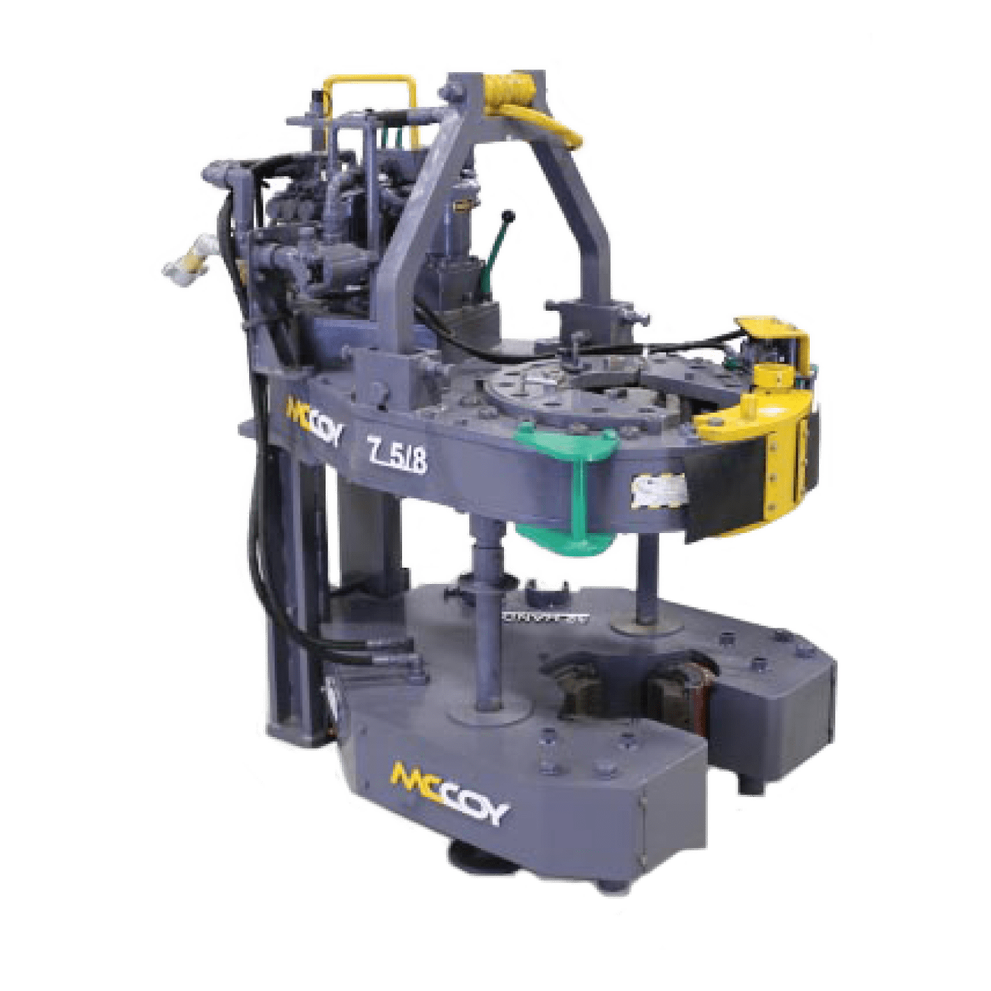
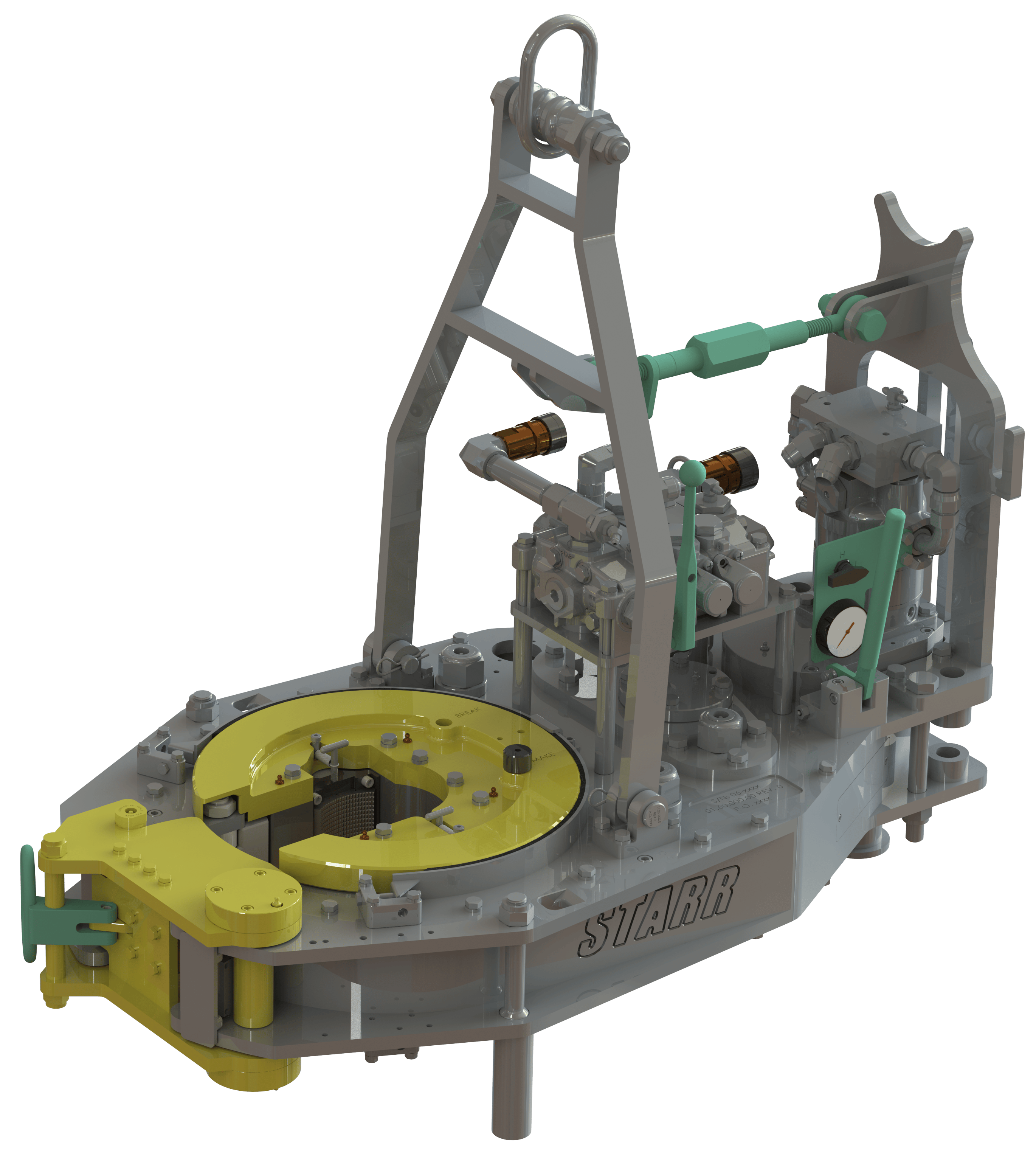
ODS International and Rogers Oil Tools (ROT) have developed a patented power tong built specifically for snubbing and well control applications (Figure 1). It is the only tong designed to ride the jack incorporated with a swinging basket.
No tong pole and no pushing or pulling of the tong on and off the pipe is necessary, which eliminates nagging injuries (broken or mashed fingers, twisted or strained backs, shoulder damage) and significantly improves the efficiency of the operation.
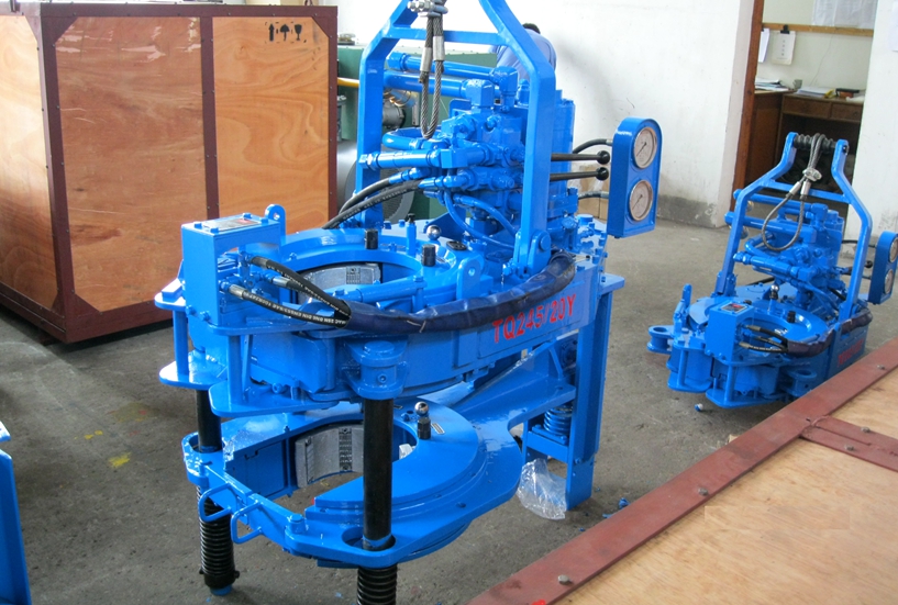
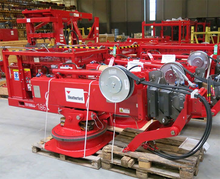
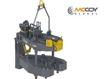
ODS-ROT can provide different models, either slip or jack-mounted (Figure 2), providing the choice of eliminating personnel in the snubbing basket by utilizing the remote operation option.
The jack head tong carries the provision of having a three-section cage plate system that can be removed to allow the jack head tong to be open for full wellbore capabilities, matching the BOP’s bore. This is the fastest and safest way to trip pipe with a snubbing unit.
Snubbing is an old technique with relatively little innovation over the past several years. The hazards associated with this type of operations still must be considered when seeking to eliminate risks.
The snubbing power tong introduced in this article is a viable alternative, making operations safer by eliminating movement of the tong on and off the pipe. This eliminates nagging injuries and increases the operational efficiency, which ultimately impacts the overall costs of well servicing programs in benefit of operator and drilling contractors.
The tong should be secured for both make-up or break-out operation, by utilizing the snub line. If this is not done, the tong may be thrown against operator causing physical harm.
To be sure connectors are completely tight, first tighten them until trave lis restricted and the end of the thread travel appears to be reached. Then try to tighten the connector further to be sure first restriction was not a false tightness. Then continue to tighten the fitting until connection is tight.
When using the mechanical shift lever to change speeds, the power tong must first come to a complete stop before shifting. When using tongs hydraulic shift two-speed motor to change speeds, the tong may be shifted "On the Run."
Eckel tongs have proven to basically to last forever with minimal maintenance as all they are manufactured with the highest quality of steel. Using Eckel equipment tells your customer that you have the highest quality equipment on the market.
Tong size is determined by range of tubulars you will run. For example a 5-1/2 Hydra-Shift® is capable of running tubulars 5-1/2-inches and smaller while the 14 UHT is capable of running tubulars 14-inches and smaller. It is important not to use a large range of sizes with just one tong. If you have a 10-3/4 Standard and you regularly run 4-1/2-inch tubing with this tong, you might consider using a smaller tong.
Determine the maximum torque that will be required to break-out the tubular you are running. There are many influences that figure in to break out torque. In some instances it requires up to 2-1/2 times the makeup torque to break out a connection.
Wrap-Around dies offer a much larger surface contact on the tubular. This distributes the force uniformly around the tubular reducing needless pipe damage due to point loading.
PSI pressure determines the maximum torque the tong will safely be able to reach. Eckel rates all their tongs at the industry standard 2500 PSI. A competitor with a similar size tong may show more or the same torque as an Eckel tong due to a higher PSI from the power unit (which is in fine print) in an effort to fool you, thinking there tong is equal to the industry standard (Eckel tong.)
Gallons Per Minute determines the rotational speed of the tong. A low GPM will cause the tong to operate at a lower speed while a high GPM will result in the tong to rotate at a higher speed. Eckel offers an RPM (Revolutions per minute) Control which is a flow divider to decrease the amount of hydraulic fluid that reaches the tong if needed, the remaining fluid is returned to the power unit reservoir. By decreasing the amount of fluid reaching the tong the operator is able to control the maximum RPM of the tong.
Field tests have shown depending on several factors most power units used in above 32 degrees Fahrenheit conditions no matter if your hydraulic oil tank holds 200 gallons of oil, will exceed 150 degrees during a short 8 hour job. Most power units without hydraulic oil coolers exceed 170 degrees which is way past the recommended guide lines.
Power Tong and Pressure Testing business for sale. Perfect set up for ambitious owner/operator. 3 sets of tongs, Farr 9 5/8, Mighty Mite 9 5/8, Mighty Mite 11 3/4. Slips & Elevators from 11 3/4 to 4 1/2 with recent certs. Cat 3507 pressure test pump. 2 ton picker, Electric reels on combo unit.
Minimum 4-5+ years related experience High School diploma, skilled labour certificate or equivalent. Strong operational and maintenance knowledge of equipment Valid Commercial Driver"s License or the ...
Minimum 4-5+ years related experience High School diploma, skilled labour certificate or equivalent. Strong operational and maintenance knowledge of equipment Valid Commercial Driver"s License or the ...
include but are not limited to: Safely and efficiently performing all tasks on the rig floor and B.O.P. area under the direction and supervision of the Driller. Operating the tongs, slips, and spinners ...
are prominent in every aspect of drilling the well, manual handling of tubular and tools, making up or breaking out during making connections or tripping pipe. The position is responsible for the processes ...
Desarrollar todas las actividades de Tubular Running Services cumpliendo con los procedimientos Operativos de la compania en cuanto a corridas de revestimientos, completamiento, produccion (Tubing), todo ...
2 or more years related field experience in the of the following disciplines Torque Turn Systems Power Tong Systems Handling Tool Systems High School diploma (or Secondary School Diploma or equivalent) ...
are prominent in every aspect of drilling the well, manual handling of tubular and tools, making up or breaking out during making connections or tripping pipe. The position is responsible for the processes ...
are prominent in every aspect of drilling the well, manual handling of tubular and tools, making up or breaking out during making connections or tripping pipe. The position is responsible for the processes ...
are prominent in every aspect of drilling the well, manual handling of tubular and tools, making up or breaking out during making connections or tripping pipe. The position is responsible for the processes ...
are prominent in every aspect of drilling the well, manual handling of tubular and tools, making up or breaking out during making connections or tripping pipe. The position is responsible for the processes ...
The Field Specialist IV will rig up, rig down and run TRS (Tubular Running Services) equipment at location with no supervision, lead and train less experienced Operators. Prepare accurate tickets, job ...
of the Floorhand include: Assisting the Derrickhand, Motorhand and Driller on the drill floor while making trips; Operating manual tongs and slips to connect and disconnect drilling pipe and drilling ...
of the Floorhand include: Assisting the Derrickhand, Motorhand and Driller on the drill floor while making trips; Operating manual tongs and slips to connect and disconnect drilling pipe and drilling ...
The present invention relates to open-head power tongs used in drilling operations, and more particularly, is directed to an improved means of actuating and deactuating the operation of the power tong drive means in response to the opened and closed positions of an access door.
As well known in the drilling industry, power tongs are employed in making-up and breaking-out operations of casings, tubings, rods, pipes and the like. More particularly, power tongs are used to grip and rotate lengths of drill pipe or the like to connect or join several lengths of pipe together to thereby form a drill string in a make-up operation, and in the alternative, to grip and rotate a length of drill pipe to disconnect it from the drill string in a break-out operation.
One type of power tong commonly used today is the open-head tong, such as the one shown and described in U.S. Pat. No. 4,060,014. The open-head tong has a bifrucated frame defining a central opening and a side opening communicating with the central opening for the passing therethrough of a drill pipe or the like. Due to the extreme costs of drilling, open-head tongs have become very popular, in that, they can easily and readily be moved into and out of an operative position when they are needed in the making up and breaking out of drill strings.
In operation, the open-head power tong exerts large rotational torques on the drill pipes, usually the larger the tong, the larger the torque output. Due to these large torque outputs and the resulting forces generated therefrom, the open-head tongs have been provided with an access door that bridges the gap between the bifrucated ends of the tong. The primary purpose of such an access door is to strengthen the tong structure so as to prevent, during the operation of the tong, the bifrucated ends from separating or springing apart, which not only results in damage to the tong, but could also inflict injury to the operating personnel. The access door, in addition to providing structural rigidity to the tong, also provides the operator with safety in bodily protecting him from the rotating pipe gripping and engaging jaws.
Such access doors perform very satisfactorily in providing structural rigidity to the tong and do provide protection to the operators from the rotating components of the tong when the door is properly latched in position during the make-up and break-out operations; however, in an effort to save time, operators have been known to operate the tong with the access door open, and in some instances, the operators have even removed the access door from the tong. Such operator"s carelessness not only causes costly structural damage to the tong, but also results in personal injury to the operator.
In U.S. Pat. No. 2,705,614 there is shown an open-head power tong having an automatic hydraulically powered access door, operably interconnected to the hydraulic cylinders that actuate the jaw gripping mechanism, which must be closed before the jaws can be actuated so as to rotate a drill pipe. Such door interlock mechanism has been specifically designed for the type of tong disclosed and is not readily adaptable to other types of power tongs, such as the one shown in the above-mentioned U.S. Pat. No. 4,060,014. Further, the hydraulic circuitry that is involved with such a powered access door is not only complicated, having expensive components, but is also, costly to maintain and repair. Still further, such door interlock mechanism does not provide adequate safety to an operator, in that, although the operator is protected from the pipe gripping and engaging mechanism when the door is closed, he is also subjected to the risk of having the power operated door being automatically swung into him as it is being closed, thus, creating a potentially dangerous and unsafe condition under which the operator must work.
The present invention obviates the problems experienced with access doors and disadvantages associated with the prior art door-interlock mechanisms by providing, as one of its principle objects, an improved door-interlock mechanism for an open-head power tong that ensures the access door is in a closed position before the tong can be operated, thereby preventing possible structural damage to the tong from operating the tong with the door open, as well as, preventing personal injury to the operators by protecting them from the various rotating components of the tong.
Another object of the present invention is to provide a door-interlock mechanism for an open-head power tong that is simple in structure and adaptable to all types of open-head power tongs.
Accordingly, the present invention, sets forth in an open-head power tong having an access door mounted on the tong and moveable between opened and closed positions, an improved door-interlock mechanism that includes means for controlling the operation of the tong in response to the opened and closed position of the door. More particularly, the control means preferably includes a pneumatic contact valve interconnected with a pneumatically piloted diverter valve operably associated with the power means of the tong such that the power means is placed in either an operative or inoperative condition in response to respective closed and opened positions of the door. Specifically, the pneumatic contact valve is so positioned in the vicinity of the side opening that the door, in its closed position, engages the contact valve thereby actuating the diverter valve to permit operation of the power means, and when, the door is moved from its closed position out of engagement with the contact valve, the contact valve causes the diverter valve to deactuate the power means, thus stopping the operation thereof.
These and other advantages and attainments of the present invention will become apparent to those skilled in the art upon reading of the following detailed description when taken in conjunction with the drawings wherein there is shown and described an illustrative embodiment of the invention.
FIG. 1 is a top plan view of an open-head power tong incorporating the improved door-interlock mechanism of the present invention with the access door being in its closed position in engagement with the contact valve which actuates the diverter valve.
FIG. 2 is a diagrammatic fragmentary view of the power tong showing the side edge portion of the access door with the door latch removed and with the contact valve being in disengagement with the door which is partly open.
Referring to the drawings, and particularly, to FIG. 1, there is shown, for illustration purposes only, an open-head power tong, being generally indicated by the numeral 10, incorporating the principles of the present invention. The tong illustrated in FIG. 1 is of the type shown and described in U.S. Pat. No. 4,060,014, and thus, for the sake of brevity, since the tong itself forms no part of this invention, only a brief description of the tong will follow.
Briefly, as best seen in FIG. 1, the power tong 10 is comprised of a bifrucated frame structure 12 defining a central drill pipe receiving opening, and a side opening that communicates to the central opening for laterally passing a drill pipe therewithin. Rotatably supported within the frame structure 12 is a pipe engaging and gripping means that includes jaws 14 that swing into and out of the central opening for gripping and rotating a drill pipe disposed within the central opening during make-up and break-out operations of a drill string. The pipe engaging and gripping means with its associated jaws 14 are rotatably driven through a suitable drive train (not shown) by power means such as the hydraulic motor 16 which receives fluid under pressure from a suitable hydraulic pump (not shown) and through a hydraulic control valve 17. The valve 17 is conventional, being moveable between three spool positions; one position being such that the fluid drives the motor in a forward clockwise direction, another position being such that the hydraulic fluid drives the motor in a reverse counterclockwise direction, and the third position being a neutral position wherein fluid passes through the valve to the return line that returns the fluid to a reservoir (not shown) for recirculation thereof.
Also supported on the frame structure 12 is an access door 18, adapted to span or bridge the access opening defined between the bifrucated end portions so as to provide structural rigidity to the power tong 10, as well as, to protect the operator from the various moving components, such as the jaws 14. One end of the access door 18 is hinged to an end of one of the frame bifrucations by a pivot pin 20 whereas the free end of the door is provided with a self-latching arm 22 that engages a latch member 24 mounted on the other bifrucation so as to positively latch the door when it is closed. The door and the door latching mechanism are of the type shown and described in a pending U.S. application, bearing U.S. Ser. No. 791,752; filed Apr. 28, 1977; and entitled TONG LOCKING MECHANISM. The door and the latching mechanism forms no part of this invention and thus a further description will not be given.
To ensure that the tong 10 is only operated when the door 18 is closed, closing the access opening, the tong 10 is provided with an interlock mechanism which basically includes a contact valve 26, engageable by the door 18, and a hydraulic diverter valve 28, operably associated with the hydraulic motor 16 so as to permit flow of hydraulic fluid to the motor, or, in the alternative position, to bypass the flow of hydraulic fluid around the motor.
As seen in FIGS. 1 and 2, in particularly FIG. 2, the contact valve 26 is mounted on the front side of the frame structure 12, in proximity to the access opening, and is so positioned to be engaged by the door 18 when the door is closed and disengaged when the door is opened. The contact valve 26 has an internal spring that biases the valve to its disengaged position. A suitable source for generating pneumatic pressure, such as a compressor (not shown) is provided to supply pressure to the valve 26 through inlet line 30 and therethrough, when valve 26 is in its engaged position, via line 62 to one end of the pneumatic piloted hydraulic diverter valve 28. When pressure is so applied on the diverter valve 28, the valve is so positioned to permit hydraulic fluid to flow to the motor 16 and thereby its operation. However, when pressure is relieved from the diverter valve 28, which is caused when the door 18 is disengaged from the contact valve 26, an internal biasing spring forces the valve to a position which diverts the flow of hydraulic flow around the motor 16, and thus, stoppage thereof.
Now turning to FIG. 3 which schematically represents the various operating components as well as the hydraulic and pneumatic circuitry associated therewith, the operation of the door interlock will be further described. First, it should be noted that both the hydraulic source and the pneumatic source are fully operating with respective fluids being under pressure in inlet lines, the access door 18 being closed, engaged with the actuating arm of the contact valve 26, the piloted diverter valve 28 being detented so as to pass the flow of hydraulic fluid around the motor 16, and with the hydraulic spool control valve 17 being in its neutral position such that fluid passes directly therethrough to the reservoir tank via inlet line 34, passageway 36, return line 38. Thus, as the spool valve 17 is shifted to its forward drive position, hydraulic fluid passes from the inlet line 34, through passageway 40, to line 42, through passageway 44 (of diverter valve 28), to line 46 which directs fluid into the left-hand side of the motor 16, and then via lines 48,49 to passageway 50 of valve 18 which is internally connected to the hydraulic return line 38. If the spool valve 17 is shifted in an opposite direction so as to reverse the direction of the motor 16, fluid flows via line 34, through passageway 52 to line 49 and line 48 to the right side of the motor 16, and then returns via lines 46, passageway 44, line 42 to passageway 54 which is internally connected to return line 38. It can be thus seen that when pressure is applied on the diverter valve 28, it is so positioned to pass hydraulic fluid either to one or the other sides of the motor 16 to thereby drive the rotating components of the tong 10 in either forward or reverse directions depending on the forward or reverse positions of the control valve 17. However, when the pneumatic pressure is relieved from the diverter valve 28, the internal spring forces the valve to the right, thus changing the flow path of the hydraulic fluid so as to bypass the motor 16. In such pressure relief position of the diverter valve 28, the fluid flow path is via lines 49,58, passageway 56 and line 42, thereby bypassing the flow of fluid to the motor 16. Since the flow of fluid through line 46 is blocked, no fluid passes to the motor 16, thus rendering it inoperative.
Thus, it can be readily appreciated from the above, that hydraulic fluid is either directed to the motor 16 for operation thereof, or bypassed therearound, preventing its operation, depending on the position of diverter valve 28. The diverter valve 28 is caused to move between its respective positions in response to the engaged and disengaged positions of the contact valve 26. In its engaged position, air under pressure passes from inlet line 30 through passageway 60 to line 62 for applying pressure to the diverter valve 28 to thereby maintain it in its retracted position wherein hydraulic fluid is permitted to pass to the motor 16. However, when the access door 18 is opened, disengaged from the contact arm of the contact valve 26, the internal spring in the contact valve 26 moves the valve to the left, thereby relieving the pressure in line 62 by venting it to the atmosphere through passageway 64, causing the internal spring to shift the position of the diverter valve 28 such that hydraulic fluid flow is bypassed around the motor 16, thus non-operation thereof.
It can be understood from the foregoing that the described interlock-mechanism controls the operation of the hydraulic motor 16, and thus the operation of the tong 10, in response to the open and closed positions of the access door 18, such that the tong 10 can only be operated with the access door 18 in its closed position, and thereby eliminating the possibility of structural damage to the tong from operating same with the door open, as well as, providing safety to the operator from exposure to the various operating components of the tong.
It is thought that the invention and many of its attendant advantages will be understood from the foregoing description and it will be apparent that various changes may be made in form, construction, and arrangement of the improved door interlock mechanism without departing from the spirit and scope of the invention or sacrificing all of its material advantages, the form hereinabove described being merely a preferred or exemplary embodiment thereof.

* Please note that all salary figures are approximations based upon third party submissions to SimplyHired or its affiliates. These figures are given to SimplyHired users for the purpose of generalized comparison only. Minimum wage may differ by jurisdiction and you should consult the employer for actual salary figures.

Contact our expert sales staff for pricing, availability and product specifications for the Gill Power Tong right for your application at the link provided on this page.

DrillingParts.com is in no way affiliated with the companies referenced in this website. References and/or mention of company names or the accompanying computer code are for ID purposes only and are not Trade Marks or Trade Names used by or affiliated with DrillingParts.com. Although under affiliate program agreements, DrillingParts.com may earn on qualifying purchases completed through third party associates such as Amazon, eBay and our marketplace vendors.


 8613371530291