
3 high pressure pup joint rack drawings supplier

Swivel loop Pup jointis cementing and fracturing equipment delivery High Pressure Fluid Control Products. Widely used in the acidic operating environment (excluding containing CO2, H2S sour gas operating environment) in the high-pressure discharge line, input line, a temporary flow line, well testing, and other high-voltage transmission lines on pipelines.
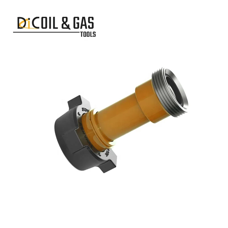
Pup jointmade of high strength steel, with a special toughening process. It uses Acme threaded connection, making it with the demolition convenient, fast, reliable connection, and reliable. Multiple seal design and high precision, to ensure the sealing performance of Pup joint.
4. Each technical parameters and performances of pup joints conform to standards of API Spec 6A and can be exchanged with like products internationally.

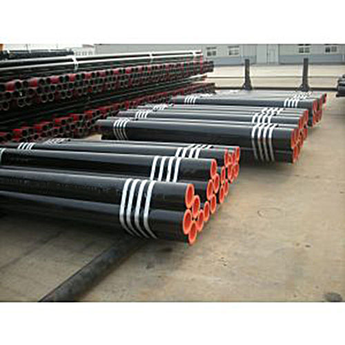
A pup joint is Casing, Pipe or Tubing shorter in length than a standard tubular string. This allows for the adjustment and installation of tools and various tubular components when placement downhole is critical for a specific project. A Spacer Pipe is another reference used to identify pup joints. Pup joint features consist of connections, lengths, weights and material grade.
Crossover pup joints are manufactured from seamless mechanical tube. As with all Crossover products, each piece is marked with a distinctive job number and heat number that is fully traceable. A complete range of sizes (1" to 4.5"), weights (standard or heavy wall), and grades (J-55, N-80, L-80, and P-110) are commonly available from stock in 2", 3", 4", 6", 10", and 12" lengths. Lengths up to 20" are available upon request.
Seamless pup joints with premium connections are available in API and exotic alloy grades. Premium ends are threaded by the manufacturer or authorized licensee.
Available with standard or special perforation spacings. Each joint has four rows of ⅜ inch holes drilled longitudinally along the tube. Optional patterns, hole size, and lengths furnished upon request.
Crossover, Inc. handles many types of API Couplings. As a rule, we stock enough of your common couplings which enable us to ship the same day if needed. We carry in stock J-55, L-80, N-80, and P-110. As for sizes, we carry 2 3/8”, 2 7/8” 3 ½”, 4 ½” tubing and some of the casing sizes up to 13 3/8”. Stock connections are EU 8 Rd., Nu 10 Rd., LTC, STC, and BTC. Our couplings are primarily of USA manufacture. If origin is not important, we can source other origins and sometimes beat the USA manufactured cost.
Swages are generally Box x Pin with a transition on the outside diameter and the inside diameter of the swage to assure that there are no sharp corners to set up an area of stress risers. When stress risers occur, there is a chance that the part could fail due to the fact that the part would be prone to crack in these areas.
A blast joint is shorter in length than standard tubular joint. Built with a heavy wall pipe it is incorporated in the production string to facilitate production across any perforated interval and zone. Blast Joints are manufactured to the following specs connections, lengths, weights and material grade.
Crossover Blast Joints are heavy wall pin by box connectors used in tubing strings and are designed to minimize the effect of external erosive action caused by production fluids. Blast joints are located opposite the location of perforations in the production casing or just below the tubing hanger in sand frac designs. Crossover blast joints are manufactured from seamless mechanical tube in sizes ranging from 2 3/8” to 4 1/2” OD. Any length, grade of material, and threading is available at the customers request. Typical lengths are 10" and 20". Both API and Premium threads are available.
Crossover Flow Couplings are heavy wall box by box connectors used in tubing strings and are designed to minimize the effect of internal erosive action caused by production fluids. Flow couplings are located just above or below Landing Nipples, Safety Valves or Control Devices where turbulent flow problems are likely to occur. Crossover flow couplings are manufactured from seamless mechanical tube in sizes ranging from 2 3/8” to 4 1/2” OD. Any length, grade of material, and threading is available at the customers request. Typical lengths are 3" and 6". Both API and Premium threads are available.
Crossover Coarse Thread Tubing Safety Joint provides for emergency recovery of the major portion of the tubing string should it become necessary to abandon the equipment below. Precision left-hand threads facilitate the release of the joint by right-hand tubing rotation. Equipment requiring right-hand rotation should not be used below the Safety joint.
Crossover Straight-Pull/Shear-Out Safety Joint is used between packers in dual and triple completions and in selective completions using Hydrostatic Single-String Packers. It is also used when rotational releasing is not desired. When ran above the upper packer in a single-string completion, however, the shear value should be adjusted to compensate for any hydraulic conditions that exist when the string is landed, or that are created by well treating operations. They are available in keyed and non-keyed configurations.
Crossover Drop Ball Circulating Subs are manufactured from AISI 4140/4145. The standard is pin by box. They are activated by dropping a chrome steel ball, which lands on a sleeve and as pressure increases, the pins in the sleeve are sheared. This causes the sleeve to move down and expose four ports in the side of the sub diverting the fluid flow.
Crossover"s Drop-in Check Valve is a retrievable check valve. It is retrievable by means of a retrievable tool (gravel girdie) run in on wireline. When needed the check valve is pumped down the drill string to the landing sub. The dogs are locked in place with pressure from below the valve. The check valve will open to allow circulation and close when circulation is stopped.
Crossover rotary shoes are manufactured from specially tempered steel to provide the ultimate in toughness and durability. They are used to cut a clearance between the fish and the wall of the well bore. Each shoe is tailored to fit a particular downhole need and normally is run on the bottom of one or more joints of washover pipe. Shoe design is dictated by whether it cuts on the bottom, on the OD, on the ID, or any combination of these. When hole sizes permit, additional clearances can be cut using side ribs, thus providing greater circulation.

Integral Pup Joints are used for transporting high-pressure flow in fracturing, cementing, maintenance, and test manifolds. These are made from high-quality alloy steel, integrally constructed, forged-ended features seamless upset construction. Standard integral pup joints are available in different models, pressure, and temperature rating.
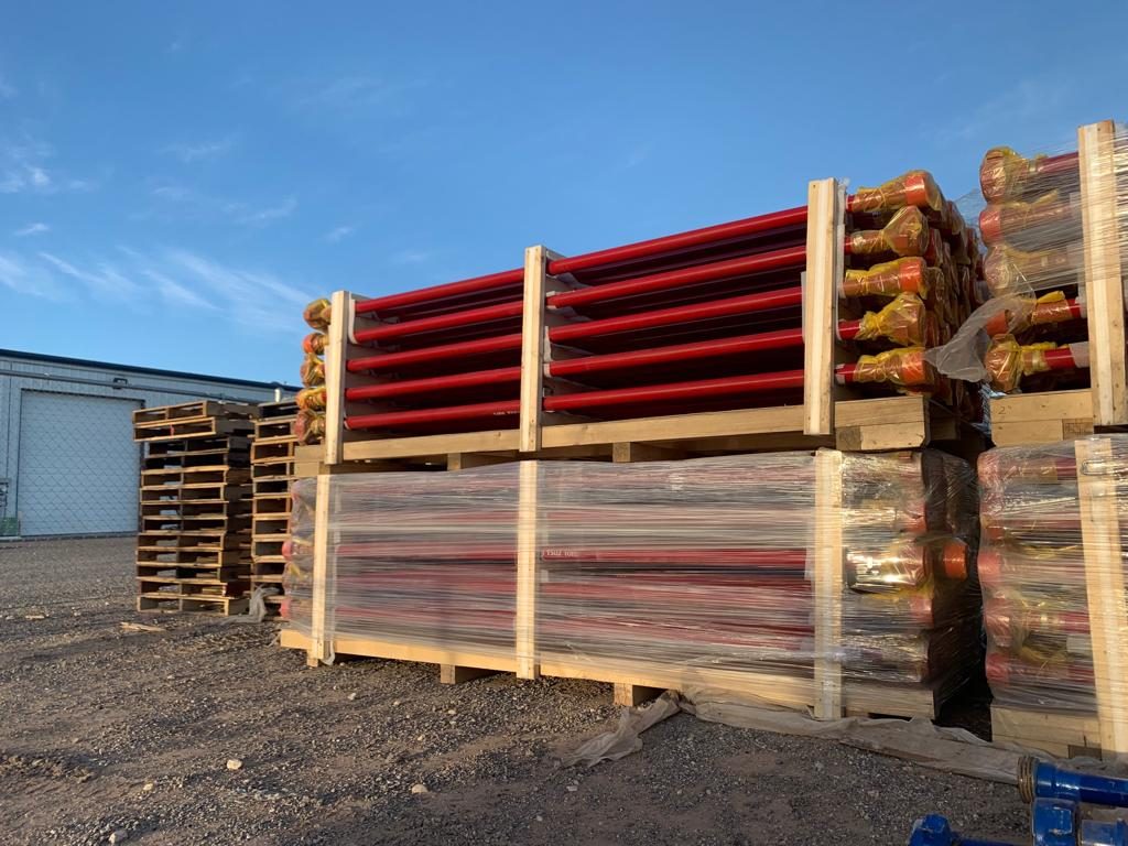
We manufacture pup joints in all sizes, grades, and thread profiles to meet any requirement. Our tubing pup joints are manufactured out of seamless tubing and machined or upset to final dimensions. All API casing and tubing pup joints are manufactured according to API Spec 5CT. Special requirements are available on request.

Integral → The pup joints are one-piece construction made from alloy steel and feature wing union end connections that eliminate welds and threads. The pup joints are capable of handling a variety of fluids and a working pressure of 15,000 psi. Available in lengths up to 15 feet, they are pressure rated to 10,000 psi for sour gas service.
Flow iron pup joints from Cameron deliver maximum total life cycle cost savings, even in the oil and gas industry’s most demanding applications. For all of your flow iron requirements, from high-stage-count hydraulic fracturing to cementing, well testing, and even abrasive flowback, you can count on Cameron for high reliability and low cost.
Maximum pressure. Under no condition shall acetylene be generated, piped (except in approved cylinder manifolds) or utilized at a pressure in excess of 15 psig (103 kPa gauge pressure) or 30 psia (206 kPa absolute). The 30 psia (206 kPa absolute) limit is intended to prevent unsafe use of acetylene in pressurized chambers such as caissons, underground excavations or tunnel construction.) This requirement is not intended to apply to storage of acetylene dissolved in a suitable solvent in cylinders manufactured and maintained according to U.S. Department of Transportation requirements, or to acetylene for chemical use. The use of liquid acetylene shall be prohibited.
All cylinders with a water weight capacity of over 30 pounds (13.6 kg) shall be equipped with means of connecting a valve protection cap or with a collar or recess to protect the valve.
Inside of buildings, cylinders shall be stored in a well-protected, well-ventilated, dry location, at least 20 feet (6.1 m) from highly combustible materials such as oil or excelsior. Cylinders should be stored in definitely assigned places away from elevators, stairs, or gangways. Assigned storage spaces shall be located where cylinders will not be knocked over or damaged by passing or falling objects, or subject to tampering by unauthorized persons. Cylinders shall not be kept in unventilated enclosures such as lockers and cupboards.
Fuel-gas cylinder storage. Inside a building, cylinders, except those in actual use or attached ready for use, shall be limited to a total gas capacity of 2,000 cubic feet (56 m3) or 300 pounds (135.9 kg) of liquefied petroleum gas.
For storage in excess of 2,000 cubic feet (56 m3) total gas capacity of cylinders or 300 (135.9 kg) pounds of liquefied petroleum gas, a separate room or compartment conforming to the requirements specified in paragraphs (f)(6)(i)(H) and (f)(6)(i)(I) of this section shall be provided, or cylinders shall be kept outside or in a special building. Special buildings, rooms or compartments shall have no open flame for heating or lighting and shall be well ventilated. They may also be used for storage of calcium carbide in quantities not to exceed 600 (271.8 kg) pounds, when contained in metal containers complying with paragraphs (g)(1)(i) and (g)(1)(ii) of this section.
Oxygen cylinders shall not be stored near highly combustible material, especially oil and grease; or near reserve stocks of carbide and acetylene or other fuel-gas cylinders, or near any other substance likely to cause or accelerate fire; or in an acetylene generator compartment.
Oxygen cylinders in storage shall be separated from fuel-gas cylinders or combustible materials (especially oil or grease), a minimum distance of 20 feet (6.1 m) or by a noncombustible barrier at least 5 feet (1.5 m) high having a fire-resistance rating of at least one-half hour.
Where a liquid oxygen system is to be used to supply gaseous oxygen for welding or cutting and the system has a storage capacity of more than 13,000 cubic feet (364 m3) of oxygen (measured at 14.7 psia (101 kPa) and 70 °F (21.1 °C)), connected in service or ready for service, or more than 25,000 cubic feet (700 m3) of oxygen (measured at 14.7 psia (101 kPa) and 70 °F (21.1 °C)), including unconnected reserves on hand at the site, it shall comply with the provisions of the Standard for Bulk Oxygen Systems at Consumer Sites, NFPA No. 566—1965, which is incorporated by reference as specified in §1910.6.
Before connecting a regulator to a cylinder valve, the valve shall be opened slightly and closed immediately. The valve shall be opened while standing to one side of the outlet; never in front of it. Never crack a fuel-gas cylinder valve near other welding work or near sparks, flame, or other possible sources of ignition.
Fuel-gas shall never be used from cylinders through torches or other devices equipped with shutoff valves without reducing the pressure through a suitable regulator attached to the cylinder valve or manifold.
Except as provided in paragraph (c)(1)(iii) of this section fuel-gas cylinders connected to one manifold inside a building shall be limited to a total capacity not exceeding 300 pounds (135.9 kg) of liquefied petroleum gas or 3,000 cubic feet (84 m3) of other fuel-gas. More than one such manifold with connected cylinders may be located in the same room provided the manifolds are at least 50 feet (15 m) apart or separated by a noncombustible barrier at least 5 feet (1.5 m) high having a fire-resistance rating of at least one-half hour.
Fuel-gas cylinders connected to one manifold having an aggregate capacity exceeding 300 pounds (135.9 kg) of liquefied petroleum gas or 3,000 cubic feet (84 m3) of other fuel-gas shall be located outdoors, or in a separate building or room constructed in accordance with paragraphs (f)(6)(i)(H) and (f)(6)(i)(I) of this section.
Separate manifold buildings or rooms may also be used for the storage of drums of calcium carbide and cylinders containing fuel gases as provided in paragraph (b)(3) of this section. Such buildings or rooms shall have no open flames for heating or lighting and shall be well-ventilated.
Oxygen manifolds shall not be located in an acetylene generator room. Oxygen manifolds shall be separated from fuel-gas cylinders or combustible materials (especially oil or grease), a minimum distance of 20 feet (6.1 m) or by a noncombustible barrier at least 5 feet (1.5 m) high having a fire-resistance rating of at least one-half hour.
Except as provided in paragraph (c)(2)(iv) of this section, oxygen cylinders connected to one manifold shall be limited to a total gas capacity of 6,000 cubic feet (168 m3). More than one such manifold with connected cylinders may be located in the same room provided the manifolds are at least 50 feet (15 m) apart or separated by a noncombustible barrier at least 5 feet (1.5 m) high having a fire-resistance rating of at least one-half hour.
An oxygen manifold, to which cylinders having an aggregate capacity of more than 6,000 cubic feet (168 m3) of oxygen are connected, should be located outdoors or in a separate noncombustible building. Such a manifold, if located inside a building having other occupancy, shall be located in a separate room of noncombustible construction having a fire-resistance rating of at least one-half hour or in an area with no combustible material within 20 feet (6.1 m) of the manifold.
An oxygen manifold or oxygen bulk supply system which has storage capacity of more than 13,000 cubic feet (364 m3) of oxygen (measured at 14.7 psia (101 kPa) and 70 °F (21.1 °C)), connected in service or ready for service, or more than 25,000 cubic feet (700 m3) of oxygen (measured at 14.7 psia (101 kPa) and 70 °F (21.1 °C)), including unconnected reserves on hand at the site, shall comply with the provisions of the Standard for Bulk Oxygen Systems at Consumer Sites, NFPA No. 566-1965.
Manifolds shall be of substantial construction suitable for use with oxygen at a pressure of 250 psig (1.7 MPa). They shall have a minimum bursting pressure of 1,000 psig (6.8 MPa) and shall be protected by a safety relief device which will relieve at a maximum pressure of 500 psig (3.4 MPa). DOT-4L200 cylinders have safety devices which relieve at a maximum pressure of 250 psig (1.7 MPa) (or 235 psig (1.6 MPa) if vacuum insulation is used).
Hose and hose connections subject to cylinder pressure shall comply with paragraph (e)(5) of this section. Hose shall have a minimum bursting pressure of 1,000 psig (6.8 MPa).
The assembled manifold including leads shall be tested and proven gas-tight at a pressure of 300 psig (2.04 MPa). The fluid used for testing oxygen manifolds shall be oil-free and not combustible.
Portable outlet headers for fuel-gas service shall be provided with an approved hydraulic back-pressure valve installed at the inlet and preceding the service outlets, unless an approved pressure-reducing regulator, an approved back-flow check valve, or an approved hydraulic back-pressure valve is installed at each outlet. Outlets provided on headers for oxygen service may be fitted for use with pressure-reducing regulators or for direct hose connection.
Piping and fittings shall comply with section 2, Industrial Gas and Air Piping Systems, of the American National Standard Code for Pressure Piping ANSI B31.1, 1967, which is incorporated by reference as specified in §1910.6, insofar as it does not conflict with paragraphs (d)(1)(i)(A)(1) and (d)(1)(i)(A)(2) of this section:
Hose connections and hose complying with paragraph (e)(5) of this section may be used to connect the outlet of a manifold pressure regulator to piping providing the working pressure of the piping is 250 psi (1.7 MPa) or less and the length of the hose does not exceed 5 feet (1.5 m). Hose shall have a minimum bursting pressure of 1,000 psig (6.8 MPa).
When oxygen is supplied to a service piping system from a low-pressure oxygen manifold without an intervening pressure regulating device, the piping system shall have a minimum design pressure of 250 psig (1.7 MPa). A pressure regulating device shall be used at each station outlet when the connected equipment is for use at pressures less than 250 psig (1.7 MPa).
Joints in steel or wrought iron piping shall be welded, threaded or flanged. Fittings, such as ells, tees, couplings, and unions, may be rolled, forged or cast steel, malleable iron or nodular iron. Gray or white cast iron fittings are prohibited.
Joints in brass or copper pipe shall be welded, brazed, threaded, or flanged. If of the socket type, they shall be brazed with silver-brazing alloy or similar high melting point (not less than 800 °F (427 °C)) filler metal.
Joints in seamless copper, brass, or stainless steel tubing shall be approved gas tubing fittings or the joints shall be brazed. If of the socket type, they shall be brazed with silver-brazing alloy or similar high melting point (not less than 800 °F (427 °C)) filler metal.
Aboveground piping systems shall be marked in accordance with the American National Standard Scheme for the Identification of Piping Systems, ANSI A13.1−1956, which is incorporated by reference as specified in §1910.6.
Piping systems shall be tested and proved gastight at 1½ times the maximum operating pressure, and shall be thoroughly purged of air before being placed in service. The material used for testing oxygen lines shall be oil free and noncombustible. Flames shall not be used to detect leaks.
Pressure relief devices. Service piping systems shall be protected by pressure relief devices set to function at not more than the design pressure of the systems and discharging upwards to a safe location.
The fuel-gas and oxygen piping systems, including portable outlet headers shall incorporate the protective equipment shown in Figures Q-1, Q-2, and Q-3. When only a portion of a fuel-gas system is to be used with oxygen, only that portion need comply with this paragraph (e)(3)(i).
Excessive back pressure of oxygen in the fuel-gas supply system. The three functions of the protective equipment may be combined in one device or may be provided by separate devices.
The protective equipment shall be located in the main supply line, as in Figure Q-1 or at the head of each branch line, as in Figure Q-2 or at each location where fuel-gas is withdrawn, as in Figure Q-3. Where branch lines are of 2-inch pipe size or larger or of substantial length, protective equipment (designated as PF) shall be located as shown in either Q-2 and Q-3.
Back-pressure protection shall be provided by an approved pressure-relief device set at a pressure not greater than the pressure rating of the backflow or the flashback protection device, whichever is lower. The pressure-relief device shall be located on the downstream side of the backflow and flashback protection devices. The vent from the pressure-relief device shall be at least as large as the relief device inlet and shall be installed without low points that may collect moisture. If low points are unavoidable, drip pots with drains closed with screw plugs or caps shall be installed at the low points. The vent terminus shall not endanger personnel or property through gas discharge; shall be located away from ignition sources; and shall terminate in a hood or bend.
A check valve, pressure regulator, hydraulic seal, or combination of these devices shall be provided at each station outlet, including those on portable headers, to prevent backflow, as shown in Figures Q-1, Q-2, and Q-3 and designated as SF and SO.
When approved pipeline protective equipment (designated PF) is located at the station outlet as in Figure Q-3, no additional check valve, pressure regulator, or hydraulic seal is required.
Where station outlets are equipped with approved backflow and flashback protective devices, as many as four torches may be supplied from one station outlet through rigid piping, provided each outlet from such piping is equipped with a shutoff valve and provided the fuel-gas capacity of any one torch does not exceed 15 cubic feet (0.42 m3) per hour. This paragraph (e)(4)(viii) does not apply to machines.
When parallel lengths of oxygen and acetylene hose are taped together for convenience and to prevent tangling, not more than 4 inches (10.2 cm) out of 12 inches (30.5 cm) shall be covered by tape.
Hose connections shall be clamped or otherwise securely fastened in a manner that will withstand, without leakage, twice the pressure to which they are normally subjected in service, but in no case less than a pressure of 300 psi (2.04 MPa). Oil-free air or an oil-free inert gas shall be used for the test.
Pressure-reducing regulators shall be used only for the gas and pressures for which they are intended. The regulator inlet connections shall comply with Regulator Connection Standards, 1958, Compressed Gas Association.
The total hourly output of a generator shall not exceed the rate for which it is approved and marked. Unless specifically approved for higher ratings, carbide-feed generators shall be rated at 1 cubic foot (0.028 m3) per hour per pound of carbide required for a single complete charge.
Relief valves shall be regularly operated to insure proper functioning. Relief valves for generating chambers shall be set to open at a pressure not in excess of 15 psig (103 kPa gauge pressure). Relief valves for hydraulic back pressure valves shall be set to open at a pressure not in excess of 20 psig (137 kPa gauge pressure).
Nonautomatic generators shall not be used for generating acetylene at pressures exceeding l psig (7 kPa gauge pressure), and all water overflows shall be visible.
The escape or relief pipe shall be carried full size to a suitable point outside the building. It shall terminate in a hood or bend located at least 12 feet (3.7 m) above the ground, preferably above the roof, and as far away as practicable from windows or other openings into buildings and as far away as practicable from sources of ignition such as flues or chimneys and tracks used by locomotives. Generating chamber relief pipes shall not be inter-connected but shall be separately led to the outside air. The hood or bend shall be so constructed that it will not be obstructed by rain, snow, ice, insects, or birds. The outlet shall be at least 3 feet (0.9 m) from combustible construction.
The gas holder may be located in the generator room, in a separate room or out of doors. In order to prevent collapse of the gas bell or infiltration of air due to a vacuum caused by the compressor or booster pump or cooling of the gas, a compressor or booster cutoff shall be provided at a point 12 inches (0.3 m) or more above the landing point of the bell. When the gas holder is located indoors, the room shall be ventilated in accordance with paragraph (f)(6)(ii) of this section and heated and lighted in accordance with paragraphs (f)(6)(iii) and (f)(6)(iv) of this section.
If acetylene is used from the gas holder without increase in pressure at some points but with increase in pressure by a compressor or booster pump at other points, approved piping protective devices shall be installed in each supply line. The low-pressure protective device shall be located between the gas holder and the shop piping, and the medium-pressure protective device shall be located between the compressor or booster pump and the shop piping (see Figure Q-4). Approved protective equipment (designated PF) is used to prevent: Backflow of oxygen into the fuel-gas supply system; passage of a flashback into the fuel-gas supply system; and excessive back pressure of oxygen in the fuel-gas supply system. The three functions of the protective equipment may be combined in one device or may be provided by separate devices.
Compressor or booster pumps shall be provided with pressure relief valves which will relieve pressure exceeding 15 psig (103 kPa gauge pressure) to a safe outdoor location as provided in paragraph (f)(4)(ii) of this section, or by returning the gas to the inlet side or to the gas supply source.
Portable generators shall not be used in rooms of total volume less than 35 times the total gas-generating capacity per charge of all generators in the room. Generators shall not be used in rooms having a ceiling height of less than 10 feet (3 m). (To obtain the gas-generating capacity in cubic feet per charge, multiply the pounds of carbide per charge by 4.5.)
When a part of the generator house is to be used for the storage or manifolding of oxygen cylinders, the space to be so occupied shall be separated from the generator or carbide storage section by partition walls continuous from floor to roof or ceiling, of the type of construction stated in paragraph (f)(6)(i)(H) of this section. Such separation walls shall be without openings and shall be joined to the floor, other walls and ceiling or roof in a manner to effect a permanent gas-tight joint.
Explosion venting for outside generator houses and inside generator rooms shall be provided in exterior walls or roofs. The venting areas shall be equal to not less than 1 square foot (0.09 m2) per 50 cubic feet (1.4 m3) of room volume and may consist of any one or any combination of the following: Walls of light, noncombustible material preferably single-thickness, single-strength glass; lightly fastened hatch covers; lightly fastened swinging doors in exterior walls opening outward; lightly fastened walls or roof designed to relieve at a maximum pressure of 25 pounds per square foot (0.001 MPa).
Calcium carbide in excess of 5,000 pounds (2,268 kg) shall be stored in one-story buildings without cellar or basement and used for no other purpose, or in outside generator houses. If the storage building is of noncombustible construction, it may adjoin other one-story buildings if separated therefrom by unpierced firewalls; if it is detached less than 10 feet (3 m) from such building or buildings, there shall be no opening in any of the mutually exposing sides of such buildings within 10 feet (3 m). If the storage building is of combustible construction, it shall be at least 20 feet (6.1 m) from any other one- or two-story building, and at least 30 feet (9.1 m) from any other building exceeding two stories.


 8613371530291