
drill pipe pup joint dimensions free sample

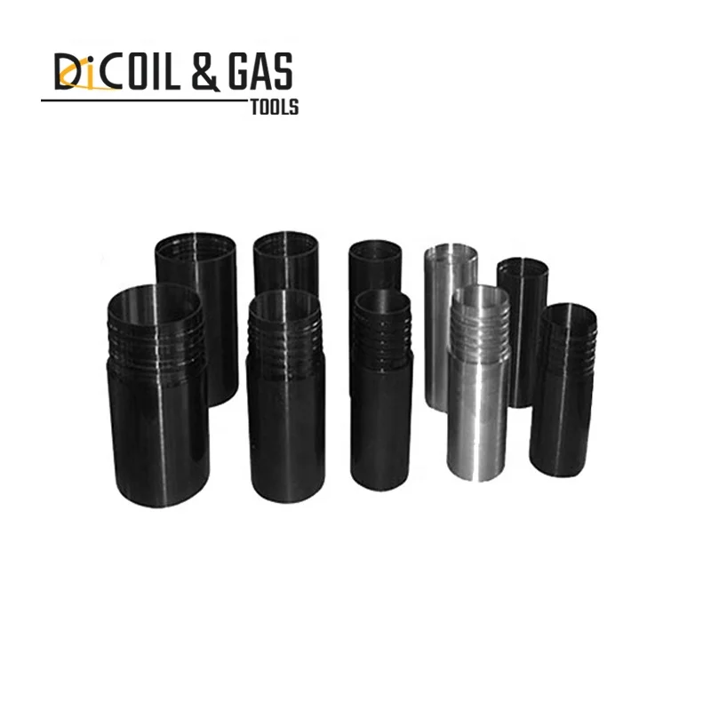
It is a short drill pipe used to adjust the overall length of drill string. The surface of Drill Pipe Pup joint looks like a smaller version of joint of drill pipe.
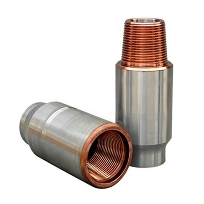
The minimum yield strength of Drill Pipe Pup Joint is 120000 PSI, just like the Tool Joint of the Drill Pipe. We manufacture Drill Pipe Pup Joints of all sizes, grades, and thread profiles to meet any custom requirements.
All our products have passed the ISO certification and API certifications.We have become the reliable exporter of Drill Pipe Pup Joint in India. Our products are tested numerous times under technical guidance and are made from best quality material.
Drill pipe joint is an important connecting component of petroleum drilling pipe drill, which is widely used in oil drilling industry. The market demand is big, has broad prospects for development, Goldenman company with its unique perspective, to create a modern international joint industry as the goal, take on the hard road of entrepreneurship. In the increasingly competitive market economy situation, the courage to struggle and thrive.

A pup joint is Casing, Pipe or Tubing shorter in length than a standard tubular string. This allows for the adjustment and installation of tools and various tubular components when placement downhole is critical for a specific project. A Spacer Pipe is another reference used to identify pup joints. Pup joint features consist of connections, lengths, weights and material grade.
Crossover pup joints are manufactured from seamless mechanical tube. As with all Crossover products, each piece is marked with a distinctive job number and heat number that is fully traceable. A complete range of sizes (1" to 4.5"), weights (standard or heavy wall), and grades (J-55, N-80, L-80, and P-110) are commonly available from stock in 2", 3", 4", 6", 10", and 12" lengths. Lengths up to 20" are available upon request.
Seamless pup joints with premium connections are available in API and exotic alloy grades. Premium ends are threaded by the manufacturer or authorized licensee.
Available with standard or special perforation spacings. Each joint has four rows of ⅜ inch holes drilled longitudinally along the tube. Optional patterns, hole size, and lengths furnished upon request.
We manufacture a wide range of Crossover Couplings. Couplings are used to connect two sizes of pipes, or two different dissimilar threaded parts together. We offer special clearance couplings, special clearance couplings with bevels on both ends, and couplings with the API Seal Ring Modification.
Crossover swages are made from API grades of pipe and mechanical tubing. Rigid quality standards are maintained throughout the manufacturing process by frequent inspection and testing. Raw material quality is assured by our quality assurance program.
A blast joint is shorter in length than standard tubular joint. Built with a heavy wall pipe it is incorporated in the production string to facilitate production across any perforated interval and zone. Blast Joints are manufactured to the following specs connections, lengths, weights and material grade.
Crossover Blast Joints are heavy wall pin by box connectors used in tubing strings and are designed to minimize the effect of external erosive action caused by production fluids. Blast joints are located opposite the location of perforations in the production casing or just below the tubing hanger in sand frac designs. Crossover blast joints are manufactured from seamless mechanical tube in sizes ranging from 2 3/8” to 4 1/2” OD. Any length, grade of material, and threading is available at the customers request. Typical lengths are 10" and 20". Both API and Premium threads are available.
Crossover Coarse Thread Tubing Safety Joint provides for emergency recovery of the major portion of the tubing string should it become necessary to abandon the equipment below. Precision left-hand threads facilitate the release of the joint by right-hand tubing rotation. Equipment requiring right-hand rotation should not be used below the Safety joint.
Crossover Straight-Pull/Shear-Out Safety Joint is used between packers in dual and triple completions and in selective completions using Hydrostatic Single-String Packers. It is also used when rotational releasing is not desired. When ran above the upper packer in a single-string completion, however, the shear value should be adjusted to compensate for any hydraulic conditions that exist when the string is landed, or that are created by well treating operations. They are available in keyed and non-keyed configurations.
A saver sub falls under the drill string accessory tool category and a short pipe that is replaceable and expendable without a major investment. This accessory protects the Kelly or topdrive component threads and those components represent a significant capital cost and considerable downtime when replaced. Saver sub are manufactured to the following specs connections, lengths, weights and material grade.
A lift sub falls under the drill string accessory tool category and utilized to mobilize various tools during drilling or fishing operations. Lift Sub are manufactured to the following specs connections, lengths, weights and material grade.
A circulating sub falls under the downhole accessory tool category that regulates flow rates, especially drilling in slimhole wells or wellbore cleanout projects. Circulating sub is manufactured to the following specs connections, lengths, weights and material grade.
A side-entry sub falls under the drilling tool accessory category to allow various drilling, fishing, wireline operations through drill pipe without interference from the rig"s top drive unit. Circulating sub is manufactured to the following specs connections, lengths, weights and material grade.
Crossover Pipe Scrubbing Wire Brush is used to brush and clean the ID of the casing and remove scale, rust, mud residue, and any other particles of debris.
These brushes are generally run on Rotary Shoulder Drill String to Brush the inside of Casing Down Hole. These brushes will remove rust, scale and other contaminates that build up on the inside diameter (ID) of the casing. Usually run in preparation of running a packer or some other piece of equipment that needs a fairly uniform ID to set.
Crossover"s Drop-in Check Valve is a retrievable check valve. It is retrievable by means of a retrievable tool (gravel girdie) run in on wireline. When needed the check valve is pumped down the drill string to the landing sub. The dogs are locked in place with pressure from below the valve. The check valve will open to allow circulation and close when circulation is stopped.
A washover pipe is Casing or Pipe shorter in length than a standard tubular string. Made of large-diameter pipe with a cutting surface at the tip, washover pipe is run in the well and then the cutting edge grinds the fish to a smooth surface and continues normal operations. Washover Pipe is manufactured to the following specs connections, lengths, weights and material grade.
Crossover rotary shoes are manufactured from specially tempered steel to provide the ultimate in toughness and durability. They are used to cut a clearance between the fish and the wall of the well bore. Each shoe is tailored to fit a particular downhole need and normally is run on the bottom of one or more joints of washover pipe. Shoe design is dictated by whether it cuts on the bottom, on the OD, on the ID, or any combination of these. When hole sizes permit, additional clearances can be cut using side ribs, thus providing greater circulation.
We manufacture pup joints in all sizes, grades, and thread profiles to meet any requirement. Our tubing pup joints are manufactured out of seamless tubing and machined or upset to final dimensions. All API casing and tubing pup joints are manufactured according to API Spec 5CT. Special requirements are available on request.

Smart drilling professionals don"t rely on dumb luck when choosing their dumb iron. Selecting the right drill pipe for the job is just as important as any other part of the drill string - and will save you time and money. Here are some questions you should take into consideration when choosing your drill pipe.
“When in Rome do as the Romans do”. Location is one of the first things you should examine when choosing a drillpipe – which brings up a lot of questions you need to consider:
Is it a HPHT well or an ordinary oil/gas well? Is it a geothermal well (hydronic bore hole)? Are you drilling onshore or offshore? From a conventional fixed platform or from a floating rig?
Are you drilling a straightforward vertical well or a directed well? Maybe a horizontal or S-shaped wellbore? Choose your drillpipe with the specific well design in mind
What formation type are you drilling in? Some formations have concentrations of sour H2S gases, which may cause sulphide stress cracking (SSC) failures or corrosion in steel drillpipe.
The deeper and the more complex and demanding the well is, the greater the risk of over torque. This can be avoided by using a double shoulder connection on your drillpipe.
The bigger the drillpipe ID, the higher capacity of bringing debris up to the surface via the annulus. Choose your drillpipe with circulation in mind.
What capacity do you have to store pipe on rig? Should you go for the standard range 2 length (31 feet per joint) or range 3 (45feet per joint). Which ranges can be handled by the pipe handling/racking system etc.?
If you have a long term need, purchasing the drilling equipment will be cheaper than renting it – with a more predictable cost, since renting equipment entails markup and handling fees that in the long run can be substantial.
P.S. In some countries rented drilling equipment can be deducted from the tax in the current year. If the rig is not active, the pipe can be sent back to the rental company. If you buy it, you will have an asset that sits in the yard, maybe for years, doing nothing. It is a lot of money to have tied up if the wheels are not turning
The tubular member of the drill string comes in a variety of sizes, strengths, and weights. Make sure that you get the most value for your dollar by choosing a quality drill pipe that is manufactured to the API, DS1 or NS1 standard. (Odfjell Well Services own more than 40 000 drillpipe joints, and if you would like to know more about standards, inspection and maintenance of drill pipe, read our e-book on the subject.)
The RIG will be mobilized from XXX to XXX. The rig will be moored in approximately xxx’ water depth. A string of 36” x 1.5” and 1.0" wall structure pipe will be jetted to xxx’ TVD / MD (xxx’ BML). The shallow hazards survey indicates possible low risk shallow gas potential from the mudline to approx. xxx’ TVD (xxx’ BML) and negligible to moderate risk shallow water flow potential at xxx’ TVD / MD (xxx’ BML).
After jetting the 36” structure pipe to the desired depth, the Drill Ahead Tool (DAT) will be used to drill 26” hole to xxx’ TVD / MD (xxx’ BML) and 20” casing will be run and cemented. The shallow water flow study indicates only low to moderate potential for over-pressured sands through this interval. Should a shallow flow be encountered while drilling riserless, 16.0 ppg kill mud will be available on the rig to control any such flow. After running and cementing 20” casing, the subsea BOP stack and riser will be run and tested. Prior to drilling out of the 20” casing, the hole will be displaced with 10.0 ppg synthetic based mud. A LOT of 10.7 ppg is expected at the 20” casing shoe. LWD (GR/RES/APWD/DIR) will be utilized in this hole section.
A 17’’ x 20” hole will be drilled to xxx’ TVD / MD and 16” casing will be run and cemented. This casing string is being set at this depth based on pore pressure and frac gradient. The expected mud weight at casing point is 10.4 ppg and the expected LOT at the 16” casing shoe is 12.4 ppg EMW. LWD (GR/RES/APWD/DIR) will be utilized in this hole section.
A 14 1/2’’ x 17 1/2” hole will be drilled to xxx’ TVD / xxx’ MD. The KOP for the directional work is planned at 7300" TVD/MD. A major azimuth change while building hole angle will be accomplished in this section using rotary steerable tools. A full string of 13 5/8” casing will be set. The expected mud weight at casing point is 12.0 ppg and the expected LOT at the 13 5/8” casing shoe is 14.2 ppg EMW. LWD (GR/RES/APWD/DIR) will be utilized in this hole section.
A 12 1/4’’ x 15" directional hole will then be drilled utilizing rotary steerable tools and LWD (GR/RES/APWD/DEN/NEUT/DIR) to xxx" TVD / xxx" MD. The 1st target zone will be encountered in this hole section at xxx" TVD. A wireline logging program consisting of GR/Dipole Sonic, RCI, and SWC will be run in this hole section. An 9 7/8" liner will be set in this hole section. The expected mud weight at casing point is 13.0 ppg and the expected LOT at the 11 7/8” casing shoe is 14.9 ppg EMW.
A 9 7/8’’ x 12 1/4" directional hole will then be drilled utilizing rotary steerable tools and LWD (GR/RES/APWD/DEN/NEUT/DIR) to xxx" TVD / xxx" MD. The primary target zones will be encountered in this hole section at xxx" TVD and xxx" TVD. A wireline logging program consisting of GR/Dipole Sonic, RCI, and SWC will be run in this hole section. A 9 7/8" liner will be set in this hole section. The expected mud weight at casing point is 14.4 ppg and the expected LOT at the 9 7/8” casing shoe is 15.8 ppg EMW.
An 8-1/2’’ hole will then be drilled to TD at xxx’ TVD / xxx’ MD utilizing rotary steerable tools and LWD (GR/RES/APWD/DEN/NEUT/DIR). The lower target zones will be encountered in this hole section at 14110" TVD and 14506" TVD. A wireline logging program consisting of GR/Dipole Sonic, RCI, SWC, MRILL, Earth Imager, and Check Shot will be run in this hole section. The expected mud weight at TD is
DWOP exercises will be conducted with drilling contractor personnel, service company personnel, COMPANY drilling supervisors and engineering staff prior to spud.
Pretension anchor chains to Contractor’s specifications for the rig. The rig will then ballast to drilling draft, and storm tension the mooring system.
The COMPANY Drilling Supervisors, Logistics Coordinator and Drilling Superintendent will prepare an initial “Required Personnel and Equipment” load-out list.
Verify 36" casing and jetting assembly tallies to ensure bit is no more than 6-8" outside the casing shoe. Adjust BHA length by the use of drill pipe pup joints and/or by cutting the 36" beveled end to fit.
P/U and stand back drill pipe and inner jetting assembly with a rock 26" bit. P/U CADA (Cam-Actuated Drill Ahead) running tool, M/U on wellhead housing and stand back.
P/U joint with beveled end x Vetco RL-4RB pin and run through rotary. Clean threads and apply AP-5 grease or lead-free API modified casing dope. Do not use any use API or other metallic- base thread compound.
Run required joints to allow 280" of penetration BML with 12" of stick up with the gas/mud mat at the ML. Make up connection and torque to recommended optimum torque. (See detailed VETCO procedure in the specific casing program section) Clean threads and apply API modified casing dope.
Record the following data on a basis: Time to jet 5", WOB, gpm, psi, comments, and notations on pipe reciprocation (when and how much the pipe was reciprocated) and the pumping of sweeps (volume and viscosity). Also note any overpull while working pipe.
Slack off weight and ensure casing is stable and remains straight. Record final bull"s eye level. Notify Drilling Superintendent if it is greater than 1.0o.
Release Vetco CADA and continue drilling next hole section as per this program. Upon pulling out of the hole, CADA will be lifted by the inner string without a special operation.
Pump 50 bbl (or slugging pit volume) hi-vis (FV > 100 sec) sweeps of seawater and prehydrated bentonite at each connection (more frequently if needed) and 50 bbl (or slugging pit volume) hi-vis pill at each half stand drilled.
Ensure MWD survey and bulls-eye indicates a wellbore angle of 1.0o or less. If 1.0o angle is exceeded, check the rig offset and consult with the Drilling Superintendent.
Shut down pumping and monitor well for flow with ROV. If well is still flowing, continue mud weight increase to kill the flow. Once well is dead, options will be discussed with members of the extended drilling team.
If a water flow is encountered, attempt to determine relative severity of flow. If water flow is minimal, consideration will be made to continue drilling to the 20” casing point. If flow is severe, increasing the mud weight or a dynamic kill will be considered. In either case, contact the COMPANY drilling staff to discuss options.
Lost circulation could occur if high annular loading results in an EMW greater than fracture gradient. Monitor APWD to determine ECD. Control drill this section at <100 ft/hr using as high of flow rates as practicable. Close observation to return flow via ROV is the only way to qualitatively tell if partial or full losses happen to occur.
Make up WHRT to 20" WH joint (with nominal seat protector and sufficient inner cement stinger to protrude from WH extension joint). Lay out on pipe rack or catwalk.
Install 2 centralizers with 1 stop collar for each centralizer on each of the bottom 3 joints. Install 1 centralizer with 1 stop collar at mid-joint on each of the next 3 joints. A total of 9 centralizers are to be run.
Collapse Caution: It is imperative that the casing string and drill pipe running string be full of fluid while running. Once the 20” shoe has entered the 36” Low Pressure Wellhead Housing, pump at least 1-1/2 casing volumes to assure that the strings are full.
Before making up WH joint, install a key-slot plate, bowl, and slips on top of the 20" casing. Pick up the 5 1/2" 21.90 ppf DP inner cementing string.
Continue running the casing on drill pipe to the mud line, filling the drill pipe every 5 stands. See Figure No. 2 at the end of this section for running weights and tensile capacities.
Monitor 20" movement at the WH with the ROV. Ensure drill pipe movement at the rig floor is consistent with casing movement at the wellhead to avoid buckling the 20" casing.
a) Record hook load every joint while running riser. Also record weights for the TDS/Traveling Block, riser running tool, tensioning ring (if not integral to telescopic joint), and diverter housing/upper flex joint. Send data to Drilling Engineer for review.
d) Pick up slip joint (closed) and landing joint and record buoyed weight of the BOPS and riser. Report weight of BOP and riser on daily drilling report. Notify office immediately if actual weight and estimated riser weight figures differ by more than 30 kips.
Test wellhead connector, shear rams, and casing to 250 / 3970 psi surface pressure while laying down the landing joint. Pressure must not decline by more than 10% in 30 minutes.
20" - 25" for rat hole is sufficient below long strings of casing, and 5" is sufficient below the liners. This limits the length of oversized, open hole below casing shoes where cuttings can accumulate. It also prevents excessive cement slump that can detrimentally effect the shoe test upon drilling out that can be a problem given the recommended cement slurry densities vs. the planned section TD MWs.
Drill with a minimum of 120 rpm with the Baker Autotrack system. If possible increase to 150 – 180 rpm. Balance ECD with the higher RPM. Watch for vibrations at the higher RPM and backoff the rpm to remove excessive vibrations.
When pumping a sweep pull the bit off bottom prior to the sweep exiting the bit. Ensure the drill string is at least 60 RPM while the sweep exits the bit. Increase the drill string rotation to a minimum of 120 RPM while pumping the maximum GPM while the sweep is moving up the annulus. Consider pumping piggyback sweeps by using a low vis then high vis sweep.
Always CBU with a maximum pump rate and maximum RPM (if possible above 150 RPM) while reciprocating the pipe. It may take up to 4 times bottoms up to clean the hole. Don’t just circulate a predetermined volume (ie 1.5 bottoms up) but circulate until the hole is clean. Don’t substitute reduced circulating time with the thought that we can backream if we see a problem.
Pumping out of the hole without drill pipe rotation is generally unacceptable and leads to backreaming conditions which often leads to packoffs and lost circulation. Pumping out without rotation can cause a cuttings bed above the BHA. If pumping is needed consider TIH a few stands and maximize GPM and rpm while pumping. Circulate clean then POOH without the pumps or rotation.
Before drilling the shoe, break circulation and circulate prior to taking slow pump rates. Check and record choke and kill line friction pressures. Perform power choke drill.
Drill out 10" of new hole. To avoid packing-off below the surface casing, pump a 200 bbl x 200 vis super-sweep (to clear the rat hole below the 20" casing) while mechanically disturbing the rat hole area by rotating a bit/stabilizer across the area at high rpm.
Once a LOT is obtained and drilling commences, pump 100 bbl x 200 vis supersweeps as necessary but at least prior to connections for 1st 300" of 17 ½" x 20" hole drilled.
Protech/Centerform composite centralizers will be Installed on the 3 joints to run as the shoe track and the 2 joints immediately above. 2 backup joints will also have the centralizers.
Collapse Caution: It is imperative that the casing string and drill pipe running string be full of fluid while running. Once the 16” shoe has entered the wellhead housing, pump at least 1 1/2 casing volumes to assure that the strings are full.
After landing in the casing hanger, makeup the ATC Cement head on drillpipe and begin pumping to close the diverter. The 2 1/4" ball will be on the seat in the Diverter Sub, pressure up to 1000 psi and hold same for 2 to 3 minutes. Continue to increase pump pressure until the ball yields the seat at 2200 to 2600 psi.
Before drilling the shoe, break circulation and circulate prior to taking slow pump rates. Check and record choke and kill line friction pressures. Perform power choke drill.
Drill out 10" of new hole. To avoid packing-off below the surface casing, pump a 200 bbl x 200 vis super-sweep (to clear the rat hole below the 16" casing) while mechanically disturbing the rat hole area by rotating a bit/stabilizer across the area at high rpm.
Once a LOT is obtained and drilling commences, pump 100 bbl x 200 vis supersweeps as necessary but at least prior to connections for 1st 300" of 14 1/2" x 17" hole drilled.
Drill hole to fit casing tally with 20" - 25" of rat hole below casing shoe. Do not drill more than 50" beyond APD shoe depth, 9600" TVD / 9692" MD RKB.
Protech/Centerform composite centralizers will be Installed on the 3 joints to run as the shoe track and the 2 joints immediately above. 2 joints to be run below the casing hanger will also have the centralizers installed. 2 backup joints will also have the centralizers.
After landing in the casing hanger, makeup the ATC Cement head on drillpipe and begin pumping to close the diverter. The 2 1/4" ball will be on the seat in the Diverter Sub, pressure up to 1000 psi and hold same for 2 to 3 minutes. Continue to increase pump pressure until the ball yields the seat at 2200 to 2600 psi.
POOH SLM and rabbit the DP using a 2 5/8” or greater OD drill pipe drift with +-120’ of wire attached and recover drift. Lay out any joints of drill pipe that do not drift. Compare to previous tally.
Have Weatherford service personnel on location. Inventory all liner equipment and tools prior to running. Double-check all lengths, OD’s, and ID’s, with Weatherford Stab Up Drawing. Verify that all dimensions are compatible with the casing and well bore.
a) Protech/Centerform composite centralizers will be Installed on the 3 joints to run as the shoe track and the 2 joints immediately above. 2 backup joints will also have the centralizers.
g) If necessary, place one pup joint with a radioactive tag approximately 300" above each reservoir to flag the sands. Pup joint placement should specified in the program addendum.
Make up liner hanger assembly. LEAVING ROTARY SLIPS SET ON LINER JOINT, pick up approximately 3 feet to verify that the setting tool and all connections are properly torqued up. Once this has been done, pull slips, slack off until PBR sleeve is accessible from the rig floor. Fill the Floating Junk Bonnet with clean water. DO NOT SET SLIPS ON SETTING SLEEVE / PBR. SET DRILL PIPE SLIPS ON SETTING TOOL LIFT SUB. Make up stand of drill pipe to the liner hanger assembly running tool and lower assembly into well. Record liner weight.
If Liner rotation is anticipated being required in open hole, calculate maximum drill down torque. Liner thread maximum make-up torque, plus rotating torque established at the casing shoe on last trip out of the hole (Step 15 above) minus 20% safety factor = maximum drill down torque. (Rotate slowly at the shoe prior to entering open hole and record minimum torque required to maintain sustained rotation. This torque to be used as reference.
When the liner is one stand off bottom, screw the Top Drive in and start pumping slowly to close the ATC Diverter Sub. Keep the pipe moving down hole during this operation. The 1 3/4" ball will be on the seat so pressure up to 600 psi slowly and hold the same for 2 or 3 minutes. Then continue to increase the pump pressure until the ball yields the seat (1500-1800 psi). Note: You will be TIH very slowly when you perform these steps.
Calculate amount of slack off required to transfer all the liner weight plus 30,000 lbs. of drill pipe weight onto the liner hanger. Space out drill string to put the Cementing Head a minimum of that distance from the rig floor once hanger is hung off and weight slacked off.
Establish pick up and slack off weights. Reciprocate liner while circulating and conditioning mud / hole. (If well conditions permit, and operator has given approval, it is recommended that the pipe be reciprocated during the mud / hole conditioning. Ensure that the reciprocation stroke is not long enough to uncover any formation that must be isolated. This will ensure that inadvertently sticking pipe will not leave that formation uncovered. (It is imperative that the driller understand that the reciprocation stroke be a slow steady movement to prevent harmful pressure surges.)
Shut down circulation. With 10-20,000 lb. of drill string weight down on liner hanger, rotate 6-8 torque free turns to the right to release setting tool from the liner. Pick up stretch in pipe plus 5"-10" to see liner weight loss ensuring that setting tool is released from the liner. Note: Ensure that setting tool is not picked up high enough to remove packer actuator sub from the PBR extension. (Double check pick up on slick joint and Floating Junk Bonnet polish nipple)
Set 30,000 lb. of drill string weight back down on liner hanger, to prevent pump out forces of cement job from inadvertently pumping the setting tool out of the liner. Prepare to cement. (Note: Slack off weight will vary from job to job. The Weatherford serviceman will figure his pump out forces on setting tool and set down sufficient weight to overcome those pump out forces)
Circulate and condition the drilling fluid for the upcoming cement job. Recommend not circulating above 30 strokes per minute until the thick mud is above the liner assembly. Circulate bottoms up (minimum 2 x bottoms up from TD to liner top). Boost riser.
Release the drillpipe dart at the tail of cement. When this dart leaves the cement head we will again see a 1500-2200 psi pressure increase as the dart exits the PLI. Minimum pump rate is 5 bpm at all times.
Displacement will be with mud. NOTE: IF SYNTHETIC DRILLING FLUIDS ARE BEING USED COMPRESSIBILITY FACTORS, IF APPLICABLE, MUST BE ENTERED INTO DISPLACEMENT FIGURES. CONSULT WITH OPERATOR RIG SUPERINTENDENT AND /OR MUD ENGINEER TO OBTAIN THIS INFORMATION.
Approximately 5 barrels prior to the drillpipe dart reaching the ATC Diverter Sub slow the pump rate to 5 bpm . The pressure required to yield the seat with the drillpipe dart should range from 1500 - 2000 psi (above the circulating pressure). After yielding the seat the drillpipe dart will latch the liner wiper plug. The pressure required to release the liner wiper plug will range from 1500 - 2000 psi (above the circulating pressure). Record pressure required to shear the plug. Continue with the displacement.
Set down minimum of 40000 lbs. (at liner top) to shear pins and energize the TSP packer (The packer actuator sub has rotational capability. Rotate drill string slowly to the right to change friction points and work weight down to the packer. Up to 100000 lbs. can be used to set packer if necessary.
Pick up setting string leaving the end of the setting tool right at the liner top Begin reversing out slowly. Once returns are obtained, pick up slowly until the end of the running tool is approximately 5 feet above the liner top. Increase pump rate and continue to pick up slowly until the end of the running tool is 10-15’ above the liner top. Once sufficient fluid has been reversed out to ensure that all excess cement (Calculated Volume) is out of annulus and either at surface or at least 2,000’ from the end of the setting tool (inside drill pipe), slow pump rate to 1-2 barrels per minute. Slowly slack off setting string inserting the end of slick stinger back into the end of the PBR tie- back extension at least 5-7 ft. Continue circulating for 3-5 minutes and then slowly pick up leaving the slick stinger 5-10 ft above the liner top. Increase pump to desired rate and complete reversing out. Reverse out two drill pipe volumes or until no cement returns are observed. Limit circulating pressure to psi while reversing out to prevent overloading the liner hanger. PRIOR TO JOB VERIFY WITH OPERATOR’S HOUSTON OFFICE THE INTENT TO REVERSE OUT EXCESS CEMENT. VERIFY WITH WEATHERFORD SERVICEMAN LIMITING CIRCULATION PRESSURES.
Pick up and RIH with jet sub, WBRT, and test-type 9 5/8" wear bushing. Wash WH thoroughly with jet sub and jet nozzle joint. Install wear bushing. If seawater was used to displace cement: Circulate out NAF mud from the upper wellhead, BOPS, riser, and choke, kill and booster lines with seawater.
POOH SLM and rabbit the DP using a 2 5/8” or greater OD drill pipe drift with +-120’ of wire attached and recover drift. Lay out any joints of drill pipe that do not drift. Compare to previous tally.
Have Weatherford service personnel on location. Inventory all liner equipment and tools prior to running. Double-check all lengths, OD’s, and ID’s, with Weatherford Stab Up Drawing. Verify that all dimensions are compatible with the casing and well bore.
Protech/Centerform composite centralizers will be Installed on each joint on each joint of casing at an interval of 1 per joint from the shoe track to 500" above the top of Galt 70 target.
Place one pup joint with a radioactive tag approximately 300" above each reservoir to flag the sands. Pup joint placement should specified in the program addendum.
Make up liner hanger assembly. LEAVING ROTARY SLIPS SET ON LINER JOINT, pick up approximately 3 feet to verify that the setting tool and all connections are properly torqued up. Once this has been done, pull slips, slack off until PBR sleeve is accessible from the rig floor. Fill the Floating Junk Bonnet with clean water. DO NOT SET SLIPS ON SETTING SLEEVE / PBR. SET DRILL PIPE SLIPS ON SETTING TOOL LIFT SUB. Make up stand of drill pipe to the liner hanger assembly running tool and lower assembly into well. Record liner weight.
If Liner rotation is anticipated being required in open hole, calculate maximum drill down torque. Liner thread maximum make-up torque, plus rotating torque established at the casing shoe on last trip out of the hole (Step 15 above) minus 20% safety factor = maximum drill down torque. (Rotate slowly at the shoe prior to entering open hole and record minimum torque required to maintain sustained rotation. This torque to be used as reference.
When the liner is one stand off bottom, screw the Top Drive in and start pumping slowly to close the ATC Diverter Sub. Keep the pipe moving down hole during this operation. The 1 3/4" ball will be on the seat so pressure up to 600 psi slowly and hold the same for 2 or 3 minutes. Then continue to increase the pump pressure until the ball yields the seat (1500-1800 psi). Note: You will be TIH very slowly when you perform these steps.
Calculate amount of slack off required to transfer all the liner weight plus 30,000 lbs. of drill pipe weight onto the liner hanger. Space out drill string to put the Cementing Head a minimum of that distance from the rig floor once hanger is hung off and weight slacked off.
Establish pick up and slack off weights. Reciprocate liner while circulating and conditioning mud / hole. (If well conditions permit, and operator has given approval, it is recommended that the pipe be reciprocated during the mud / hole conditioning. Ensure that the reciprocation stroke is not long enough to uncover any formation that must be isolated. This will ensure that inadvertently sticking pipe will not leave that formation uncovered. (It is imperative that the driller understand that the reciprocation stroke be a slow steady movement to prevent harmful pressure surges.)
Shut down circulation. With 10-20,000 lb. of drill string weight down on liner hanger, rotate 6-8 torque free turns to the right to release setting tool from the liner. Pick up stretch in pipe plus 5"-10" to see liner weight loss ensuring that setting tool is released from the liner. Note: Ensure that setting tool is not picked up high enough to remove packer actuator sub from the PBR extension. (Double check pick up on slick joint and Floating Junk Bonnet polish nipple)
Set 30,000 lb. of drill string weight back down on liner hanger, to prevent pump out forces of cement job from inadvertently pumping the setting tool out of the liner. Prepare to cement. (Note: Slack off weight will vary from job to job. The Weatherford serviceman will figure his pump out forces on setting tool and set down sufficient weight to overcome those pump out forces)
Circulate and condition the drilling fluid for the upcoming cement job. Recommend not circulating above 30 strokes per minute until the thick mud is above the liner assembly. Circulate bottoms up (minimum 2 x bottoms up from TD to liner top). Boost riser.
Release the drillpipe dart at the tail of cement. When this dart leaves the cement head we will again see a 1500-2200 psi pressure increase as the dart exits the PLI. Minimum pump rate is 5 bpm at all times.
Displacement will be with mud. NOTE: IF SYNTHETIC DRILLING FLUIDS ARE BEING USED COMPRESSIBILITY FACTORS, IF APPLICABLE, MUST BE ENTERED INTO DISPLACEMENT FIGURES. CONSULT WITH OPERATOR RIG SUPERINTENDENT AND /OR MUD ENGINEER TO OBTAIN THIS INFORMATION.
Approximately 5 barrels prior to the drillpipe dart reaching the ATC Diverter Sub slow the pump rate to 5 bpm . The pressure required to yield the seat with the drillpipe dart should range from 1500 - 2000 psi (above the circulating pressure). After yielding the seat the drillpipe dart will latch the liner wiper plug. The pressure required to release the liner wiper plug will range from 1500 - 2000 psi (above the circulating pressure). Record pressure required to shear the plug. Continue with the displacement.
Set down minimum of 40000 lbs. (at liner top) to shear pins and energize the TSP packer (The packer actuator sub has rotational capability. Rotate drill string slowly to the right to change friction points and work weight down to the packer. Up to 100000 lbs. can be used to set packer if necessary.
Pick up setting string leaving the end of the setting tool right at the liner top Begin reversing out slowly. Once returns are obtained, pick up slowly until the end of the running tool is approximately 5 feet above the liner top. Increase pump rate and continue to pick up slowly until the end of the running tool is 10-15’ above the liner top. Once sufficient fluid has been reversed out to ensure that all excess cement (Calculated Volume) is out of annulus and either at surface or at least 2,000’ from the end of the setting tool (inside drill pipe), slow pump rate to 1-2 barrels per minute. Slowly slack off setting string inserting the end of slick stinger back into the end of the PBR tie- back extension at least 5-7 ft. Continue circulating for 3-5 minutes and then slowly pick up leaving the slick stinger 5-10 ft above the liner top. Increase pump to desired rate and complete reversing out. Reverse out two drill pipe volumes or until no cement returns are observed. Limit circulating pressure to psi while reversing out to prevent overloading the liner hanger. PRIOR TO JOB VERIFY WITH OPERATOR’S HOUSTON OFFICE THE INTENT TO REVERSE OUT EXCESS CEMENT. VERIFY WITH WEATHERFORD SERVICEMAN LIMITING CIRCULATION PRESSURES.

Tests under bottom hole temperatures ranging from 50° through 400° F showed Forumlok withstood greater torque than a standard joint welded in three places with 2 inch beads.
At 400° F Forumlok was subjected to a steady breakout torque for 8 hours while under continuous vibration from a 6 pound air hammer. Breakout torque was increased until six times the 3,300 ft-lb makeup torque finally broke the joint.
Tests were made using Forumlok on one side of a standard coupling and API Modified Thread Dope on the other. Identical pin threads were made up into the coupling. For the same amount of torque, the joint with Forumlok made up further and was cooler than the joint lubricated with standard thread dope. Forumlok has a 1.18 Friction Factor/Torque Factor.
Joints made up with Forumlok using standard torque were tested with water pressures in excess of the listed burst pressure of the casing. The joint showed no leakage.


 8613371530291