
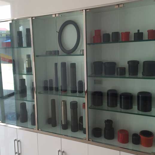
filter pup joint screen factory
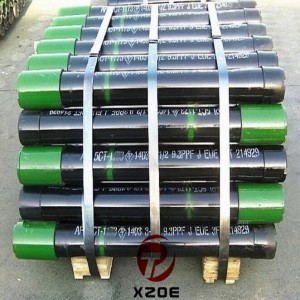
Manufacturer of pressure, rig concept, well intervention, drilling, down-hole and tubular products. Pressure products include centering shear and fixed bore pipe rams, blowout preventers, diverter systems, connectors, check and gate valves, chokes, actuators, flow heads, manifolds, catchers, packers, hydrate seals, casing heads, casing and tubing head spools, adapters, and hangers. Rig concept products include rig packages, derricks, masts, and skidding systems. Drilling products include electric and hydraulic top drives, makeup/breakout units, pipe handling units, cabins, operation stations, chairs, automatic drillers, anti-collision systems, and navigators, and draw works. Down-hole products include coiled tubing orienteers, drilling motors and jars, and survey and shock tools. Tabular products include drill pipe connections, collars, Kelly’s, subs and pup joints, and pipes.
The Hunting Downhole Filter is a simple tool that is run above any debris intolerant tool to ensure full operability. This is particularly useful when cleanliness of circulating fluid is poor, unknown or whilst recirculating the same fluid.
Available in a variety of sizes, Drilling Tools" filter subs range from the retrievable and non-retrievable mud screens to the Diffuser™ blade technology sub assembly. See detailed information on
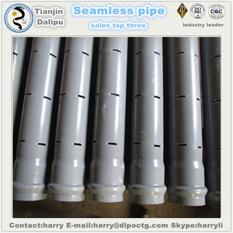
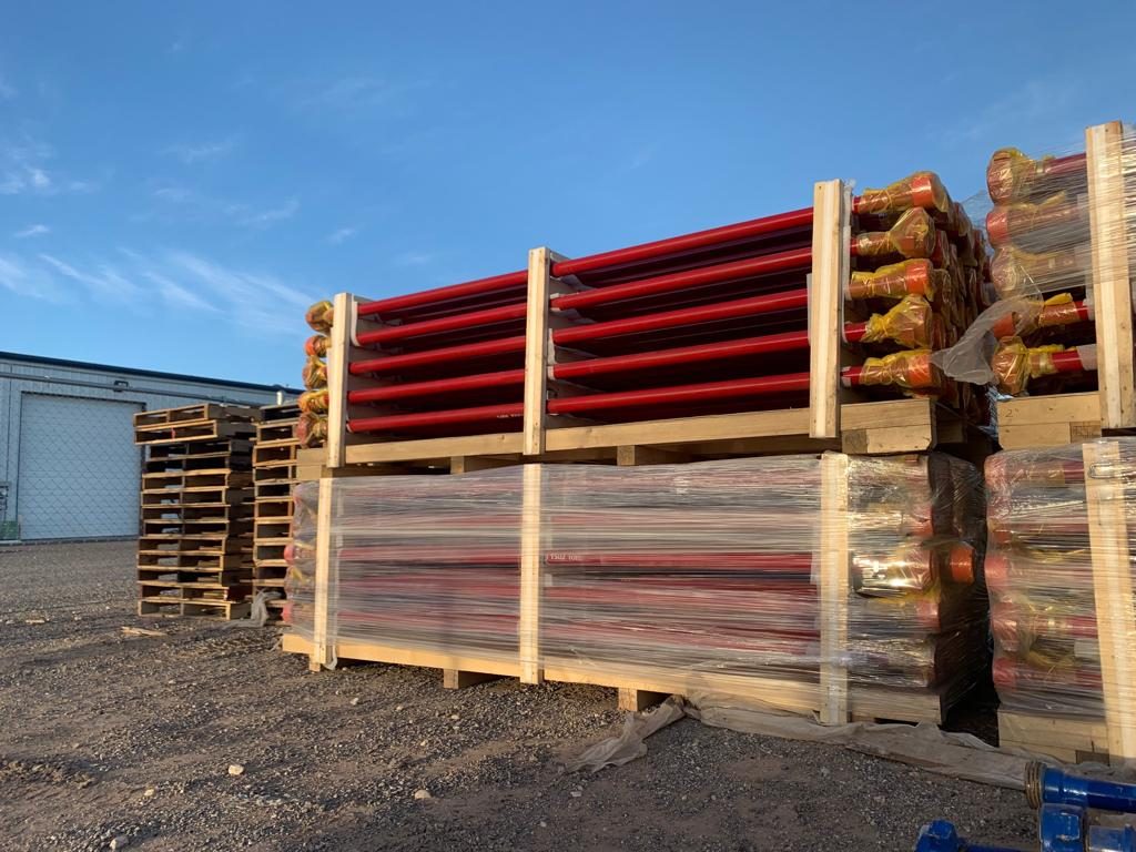
Pup joints are key components in special drilling operations when specific spacing considerations are required. Our pup joints can be ordered with an 18-degree taper or square shoulder and with pressed
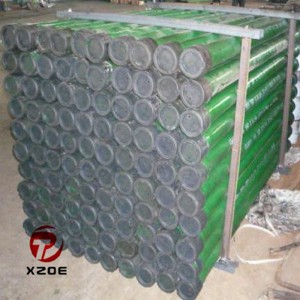
The utility model relates to the filter assemblies in a kind of chemical plant installations, comprise multiple screen pipe be installed in pallet, the lower end of screen pipe connects block, the outer wall of screen pipe is equipped with steel wire, the lower end of described screen pipe is with internal thread, block is with external screw thread, and screen pipe is connected with block spiral.Screen pipe of the present utility model and block adopt screw joining manner, and compare and be welded to connect, it is easy for installation, be convenient to dismounting and change, replacement cost is low, also convenient cleaning.
Filter is the important devices for unstrpped gas being carried out purification filtering, is the important component part in chemical industry equipment.Critical component in filter is screen pipe assembly, in prior art, screen pipe assembly comprises screen pipe, block, steel wire and pallet, and multiple screen pipe is installed in pallet, screen pipe and block are welded and fixed, and wire sets is placed in the outer wall of block and screen pipe.The shortcoming that the screen pipe assembly of this structure exists is: screen pipe and block are welded to connect, and weld comparatively consuming time; When one of them is damaged and need changes, because the two can not be dismantled, its replacement cost is higher; During screen pipe cleaning, baffle plate closes its end, and cleaning is inconvenient, not thorough.
The above-mentioned shortcoming that the applicant exists for prior art, carries out studying and improving, and provides that a kind of structure is simple, filter assemblies in the chemical plant installations of easy disassembly.
A filter assemblies in chemical plant installations, comprises multiple screen pipe be installed in pallet, and the lower end of screen pipe connects block, the outer wall of screen pipe is equipped with steel wire, the lower end of described screen pipe is with internal thread, and block is with external screw thread, and screen pipe is connected with block spiral.
Screen pipe of the present utility model and block adopt screw joining manner, and compare and be welded to connect, it is easy for installation, be convenient to dismounting and change, replacement cost is low, also convenient cleaning.
As shown in Figure 1, filter assemblies in the chemical plant installations of the present embodiment, comprise multiple screen pipe 2 be installed in pallet 1, the lower end of screen pipe 2 connects block 4, the outer wall of screen pipe 2 is equipped with steel wire 3, the lower end of screen pipe 2 is with internal thread, block 4 is the tubular structure with blind end, it is with mounting flange 41, the outer wall of mounting flange 41 is with the external screw thread coordinated with screen pipe 2, block 4 is connected with screen pipe 2 spiral by mounting flange 41, the external diameter of screen pipe 2 is equal with the external diameter of block 4, namely after screen pipe 2 is connected with block 4, the outer wall of the two flushes, facilitate the installation of steel wire 3.
Screen pipe of the present utility model and block adopt screw joining manner, and compare and be welded to connect, it is easy for installation, be convenient to dismounting and change, replacement cost is low, also convenient cleaning.
1. the filter assemblies in a chemical plant installations, comprise multiple screen pipe (2) be installed in pallet (1), the lower end of screen pipe (2) connects block (4), the outer wall of screen pipe (2) is equipped with steel wire (3), it is characterized in that: the lower end of described screen pipe (2) is with internal thread, block (4) is with external screw thread, and screen pipe (2) is connected with block (4) spiral.
2. the filter assemblies in chemical plant installations as claimed in claim 1, it is characterized in that: described block (4) is with mounting flange (41), and the outer wall of mounting flange (41) is with the external screw thread coordinated with screen pipe (2).
3. the filter assemblies in chemical plant installations as claimed in claim 1 or 2, is characterized in that: the external diameter of described screen pipe (2) is equal with the external diameter of block (4).
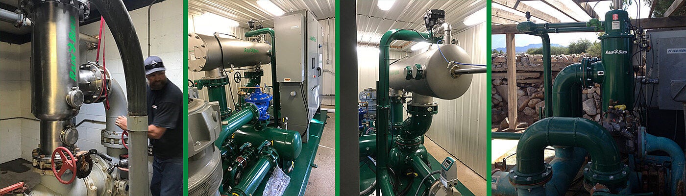
Strainer can be defined as a pipe fitting through which liquid is passed for purification, filtering or separation from solid matter; anything used to strain a liquid; any device functioning as a sieve or filter used to prevent solid bodies from mixing in a liquid stream or flowline.
Strainers arrest pipeline debris such as scale, rust, jointing compound and weld metal in pipelines, protecting equipment and processes from their harmful effects, thus reducing downtime and maintenance. Use of rightly selected strainers at correct locations (usually upstream) is a must to protect expensive and critical downstream equipment such as pumps, flow meters, steam traps, control valves etc.
In Y-type strainer the filter leg connects to the main pipe at a diagonal angle, giving the strainer its “y” shape, and hence its name. This type is commonly used in pressurized lines, steam, liquid or gas, but can also be applied in vacuum or suction situation.
A Y-strainer can be installed in either a horizontal or vertical position (Downward flow) with the screen element pointing downward. This allows the strainer screen to collect material in the strainer at the lowest point of the screen.
To service a basket type strainer, the cover can be removed so technicians get immediate access to the filtering element if it needs replacement (due to accumulated debris). When basket type strainers are used on steam systems, a significant amount of condensate may be formed. Consequently, strainers designed for use in steam systems usually have a drain plug, which can be fitted with a steam trap to remove the condensate.
These are formed by punching a large number of holes in a flat sheet of the required material using a multiple punch. The perforated sheet is then rolled into a tube and spot welded together. These are relatively coarse screens and hole sizes typically range from 0.8 mm to 3.2 mm. Consequently, perforated screens are only suitable for removing general pipe debris.
Fine wire is formed into a grid or mesh arrangement. This is then commonly layered over a perforated screen, which acts as a support cage for the mesh. By using a mesh screen, it is possible to produce much smaller hole sizes than with perforated screens. Hole sizes as small as 0.07 mm are achievable. Subsequently, they are used to remove smaller particles which would otherwise pass through a perforated screen. Mesh screens are usually specified in terms of ‘mesh’; which represents the number of openings per linear inch of screen, measured from the centre line of the wire.
A filter is a device that removes particles from a given liquid or gas. It includes a disposable medium for removing particles of specified micron sizes. All strainers are filters, but all filters are not strainers. A strainer is only one type of filter. Strainer uses a perforated plate or screen mesh to remove larger particles from a process stream. The major advantage of a Strainer is that it is reusable. The filter screen is only used once and must be changed when it clogs.
The main difference seems to be in diameter of the holes in the media screen also termed as mesh size in case of strainer. There is no hard and fast size division to define strainers from filters. Filters capable of removing particles as small as 1 μm are available
Another difference is resistance. Strainers normally present low resistance to liquid flow. The pressure drop across most strainers is relatively small compared with the pressure drop across thick media filters or membrane filters.
Another difference is the function. A strainer is used to protect other downstream equipment (e.g., pumps, instrumentation) from damage by rogue junk. A filter is employed to separate particles from the fluid.
Early surveys to determine asbestos exposures were conducted using impinger counts of total dust with the counts expressed as million particles per cubic foot. The British Asbestos Research Council recommended filter membrane counting in 1969. In July 1969, the Bureau of Occupational Safety and Health published a filter membrane method for counting asbestos fibers in the United States. This method was refined by NIOSH and published as P CAM 239. On May 29, 1971, OSHA specified filter membrane sampling with phase contrast counting for evaluation of asbestos exposures at work sites in the United States. The use of this technique was again required by OSHA in 1986. Phase contrast microscopy has continued to be the method of choice for the measurement of occupational exposure to asbestos.
Air is drawn through a MCE filter to capture airborne asbestos fibers. A wedge shaped portion of the filter is removed, placed on a glass microscope slide and made transparent. A measured area (field) is viewed by PCM. All the fibers meeting defined criteria for asbestos are counted and considered a measure of the airborne asbestos concentration.
2.1. The ideal counting range on the filter is 100 to 1,300 fibers/mm2. With a Walton-Beckett graticule this range is equivalent to 0.8 to 10 fibers/field. Using NIOSH counting statistics, a count of 0.8 fibers/field would give an approximate coefficient of variation (CV) of 0.13.
Precision is dependent upon the total number of fibers counted and the uniformity of the fiber distribution on the filter. A general rule is to count at least 20 and not more than 100 fields. The count is discontinued when 100 fibers are counted, provided that 20 fields have already been counted. Counting more than 100 fibers results in only a small gain in precision. As the total count drops below 10 fibers, an accelerated loss of precision is noted.
5.1.1. Sample assembly (The assembly is shown in Figure 3). Conductive filter holder consisting of a 25-mm diameter, 3-piece cassette having a 50-mm long electrically conductive extension cowl. Backup pad, 25-mm, cellulose. Membrane filter, mixed-cellulose ester (MCE), 25-mm, plain, white, 0.4 to 1.2-µm pore size.
(c) Purchase filters which have been selected by the manufacturer for asbestos counting or analyze representative filters for fiber background before use. Discard the filter lot if more than 4 fibers/100 fields are found.
(d) To decrease the possibility of contamination, the sampling system (filter-backup pad-cassette) for asbestos is usually preassembled by the manufacturer.
5.2.4. Select an appropriate flow rate for the situation being monitored. The sampling flow rate must be between 0.5 and 5.0 L/min for personal sampling and is commonly set between 1 and 2 L/min. Always choose a flow rate that will not produce overloaded filters.
5.2.8. The most significant problem when sampling for asbestos is overloading the filter with non-asbestos dust. Suggested maximum air sample volumes for specific environments are:
Caution: Do not overload the filter with dust. High levels of non-fibrous dust particles may obscure fibers on the filter and lower the count or make counting impossible. If more than about 25 to 30% of the field area is obscured with dust, the result may be biased low. Smaller air volumes may be necessary when there is excessive non-asbestos dust in the air.
While sampling, observe the filter with a small flashlight. If there is a visible layer of dust on the filter, stop sampling, remove and seal the cassette, and replace with a new sampling assembly. The total dust loading should not exceed 1 mg.
5.2.10. Immediately after sampling, close and seal each cassette with the base and plastic plugs. Do not touch or puncture the filter membrane as this will invalidate the analysis.
5.2.11. Attach and secure a sample seal around each sample cassette in such a way as to assure that the end cap and base plugs cannot be removed without destroying the seal. Tape the ends of the seal together since the seal is not long enough to be wrapped end-to-end. Also wrap tape around the cassette at each joint to keep the seal secure.
6.1.2. Any asbestos spills should be cleaned up immediately to prevent dispersal of fibers. Prudence should be exercised to avoid contamination of laboratory facilities or exposure of personnel to asbestos. Asbestos spills should be cleaned up with wet methods and/or a High Efficiency Particulate-Air (HEPA) filtered vacuum.
Note: See Safety Precautions in Section 6.1. before proceeding. The objective is to produce samples with a smooth (non-grainy) background in a medium with a refractive index of approximately 1.46. The technique below collapses the filter for easier focusing and produces permanent mounts which are useful for quality control and interlaboratory comparison.
6.5.3. Remove the top plug to prevent a vacuum when the cassette is opened. Clean the outside of the cassette if necessary. Cut the seal and/or tape on the cassette with a razor blade. Very carefully separate the base from the extension cowl, leaving the filter and backup pad in the base.
6.5.4. With a rocking motion cut a triangular wedge from the filter using the scalpel. This wedge should be one-sixth to one-fourth of the filter. Grasp the filter wedge with the forceps on the perimeter of the filter which was clamped between the cassette pieces. DO NOT TOUCH the filter with your finger. Place the filter on the glass slide sample side up. Static electricity will usually keep the filter on the slide until it is cleared.
6.5.5. Place the tip of the micropipette containing about 200 µL acetone into the aluminum block. Insert the glass slide into the receiving slot in the aluminum block. Inject the acetone into the block with slow, steady pressure on the plunger while holding the pipette firmly in place. Wait 3 to 5 seconds for the filter to clear, then remove the pipette and slide from the aluminum block.
6.5.6. Immediately (less than 30 seconds) place 2.5 to 3.5 µL of triacetin on the filter (Note: Waiting longer than 30 seconds will result in increased index of refraction and decreased contrast between the fibers and the preparation. This may also lead to separation of the cover slip from the slide).
6.5.7. Lower a cover slip gently onto the filter at a slight angle to reduce the possibility of forming air bubbles. If more than 30 seconds have elapsed between acetone exposure and triacetin application, glue the edges of the cover slip to the slide with lacquer or nail polish.
(3) Continually scan over a range of focal planes (generally the upper 10 to 15µm of the filter surface) with the fine focus control during each field count. Spend at least 5 to 15 seconds per field.
Note: The collection area of a filter is seldom equal to 385 mm2. It is appropriate for laboratories to routinely monitor the exact diameter using an inside micrometer. The collection area is calculated according to the formula:
Since a given analyst always has the same interpupillary distance, the number of fields per filter for a particular analyst will remain constant for a given size filter. The field size for that analyst is constant (i.e. the analyst is using an assigned microscope and is not changing the reticle).
For example, if the exposed area of the filter is always 385 mm2 and the size of the field is always 0.00785 mm2, the number of fields per filter will always be 49,000. In addition it is necessary to convert liters of air to cc. These three constants can then be combined such that ECA/(1,000 X MFA) = 49. The previous equation simplifies to:
As mentioned in step 13 of Section 6.6.2., a "blind recount" of 10% of the slides is performed. In all cases, differences will be observed between the first and second counts of the same filter wedge. Most of these differences will be due to chance alone, that is, due to the random variability (precision) of the count method. Statistical recount criteria enables one to decide whether observed differences can be explained due to chance alone or are probably due to systematic differences between analysts, microscopes, or other biasing factors.
If a pair of counts are rejected by this criterion then, recount the rest of the filters in the submitted set. Apply the test and reject any other pairs failing the test. Rejection shall include a memo to the industrial hygienist stating that the sample failed a statistical test for homogeneity and the true air concentration may be significantly different than the reported value.
8.2. Asbestos Research Council: The Measurement of Airborne Asbestos Dust by the Membrane Filter Method (Technical Note), Asbestos Research Council, Rockdale, Lancashire, Great Britain, 1969.
8.3. Bayer, S.G., Zumwalde, R.D., Brown, T.A., Equipment and Procedure for Mounting Millipore Filters and Counting Asbestos Fibers by Phase Contrast Microscopy, Bureau of Occupational Health, U.S. Dept. of Health, Education and Welfare, Cincinnati, OH, 1969.
8.9. Leidel, N.A., Bayer,S.G., Zumwalde, R.D.,Busch, K.A., USPHS/NIOSH Membrane Filter Method for Evaluating Airborne Asbestos Fibers (DHEW/NIOSH Pub. No. 79-127). National Institute for Occupational Safety and Health, Cincinnati, OH, 1979.
(7) Each eyepiece-objective-reticle combination on the microscope must be calibrated. Should any of the three be changed (by zoom adjustment, disassembly, replacement, etc.), the combination must be recalibrated. Calibration may change if interpupillary distance is changed. Measure the field diameter, D (acceptable range: 100 ± 2 µm) with a stage micrometer upon receipt of the graticule from the manufacturer. Determine the field area (mm2).


 8613371530291