
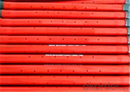
perforated pup joint function made in china

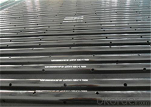
We are Supplier and Exporter of Perforated Pup Joints in UAE. It is usually installed between the bottom of two nipples of a completion. It allows unrestricted fluid or gas flow, which increases the accuracy and reliability of acquired downhole production data.
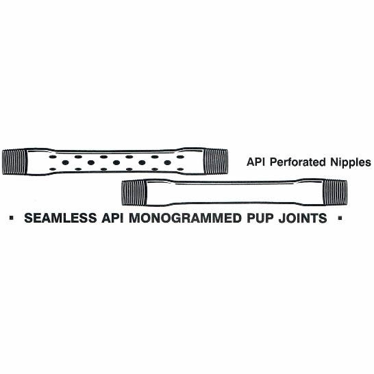
We supply all sizes, grades, and thread profiles to meet custom requirements. The perforated pup joints are sometimes also known as the perforated production tube. All our products have passed the ISO certification and API certifications. Our products are tested numerous times under technical guidance and are made from the best quality material.
This website uses cookies to improve your experience while you navigate through the website. Out of these, the cookies that are categorized as necessary are stored on your browser as they are essential for the working of basic functionalities of the website. We also use third-party cookies that help us analyze and understand how you use this website. These cookies will be stored in your browser only with your consent. You also have the option to opt-out of these cookies. But opting out of some of these cookies may affect your browsing experience.
One is a short Drill Pipe used to adjust the length of the Drill String; The other one OCTG Pup Joint is a pipe of non-standard length, which is used to adjust the length of tubular strings to its exact requirement.
Vigor can manufacture the Tubing Pup Joints by different technology - Upsetting and Machining process. if you have a special requirement on the Pup Joint production process, please just specify.
If you are looking for a competitive, high quality and fast delivery oilfield pup joint in stock, or if you are planning to buy pup joint API from one of the leading casing and tubing pup joint manufacturers, API 5CT pup joint in stock, l8013cr pup joint, nue/nue tubing pup joint manufacturers and suppliers China, please feel free to contact VIGOR.Details of API Spec. 5CT Oil Tubing Pup Joint

Failure: Deformation, fracture, surface damage and loss of original function under specific service conditions. The main forms of oil casing failure are: crushing, slipping, cracking, leakage, corrosion, adhesion, wear and the like.
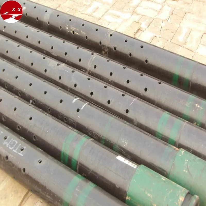
In wells flowing large volumes, a restriction in the tubing such as a gauge hanger, could cause false pressure readings. Vibrations due to flow could also cause extensive damage to delicate gauges, therefore a perforated pup joint (approx. 10ft length) set above the bomb hanger nipple would allow flow to pass unrestricted over the gauges and hanger, thus giving a more accurate pressure/temperature recording within the

Pipe system involves various components, including perforated pup joints and are made from different materials. We offer wholesale perforated pup joints to create a smooth channel for the pipe systems in both commercial and residential areas.
Our range of products include Blank Adapter SH-500-A, Box-Box Flow Coupling SH502-FC, Combination Adapter SH-500-A, Combination Flow Coupling SH502-FC, Coupled Pup Joint SH503-PJ and Open Hole Hydraulic Set Packer SH518-OHP.
The Bullnose is a blanking device used at the end of the string. Its primary function is to prevent flow from entering the bottom end of the string, whilst its rounded nose design provides a positives guide while running in hole. Bull noses come in standard tool joint thread configurations and can be modified on location to best fit the application for which they are being used.

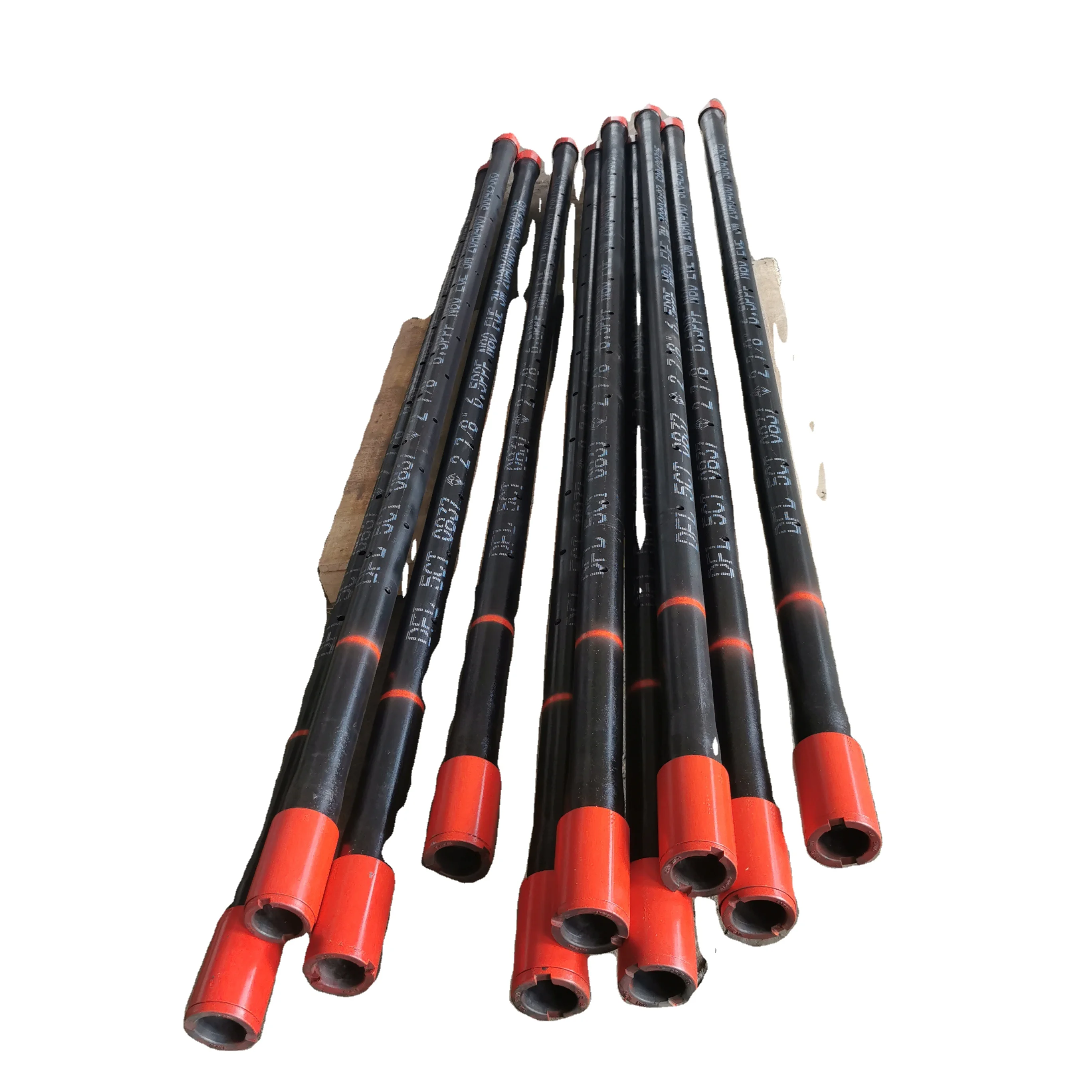
Pup joint is a short version of oil tubing pipe, and pup joint function is to adjust RIH-run in hole depth of tubing or downhole tools for oil and gas drilling and production in oilfiled.
7.Our tubing pup joint conform to API Spec 5CT and API Spec 5B standards, the pup joint length is 2’. 4’.6’.8’10’ 12’ and we can make different lengths and sizes upon clients" requests.
Dongying Mingde Petroleum Technology Co., Ltd, established in 1992, is one of the top professional pup joint manufacturing companies in China. We can provide casing, tubing, pup joint, crossover, slotted liner, downhole sand control screen pipe, as well as oilfield services.
Drill Pipe: Drill pipe includes pipe body and tool joints(box and pin) welded together, used to connect drilling rig surface equipment and bottom equipment or bottom hole equipment. Drill pipe can bear heavy internal and external pressure, and twist, bend and vibration which can be used more than one time during oil or gas production.
Drill pipes are steel tube fitted with threaded ends called tool joints, which are commonly used in tension in the top part of the drill string to pump fluid an...
Slotted pipe works as a separator to filtrate the sand in oil or gas well, the main function is to control sand. Different grade and type (slotted, perforated, wire-wrapped and so on) of pipes will be applied for different stratum during oil and gas exploration.
Couplings are short lengths of pipe used to connect 2 joints of tubing or casing. They come with painted color codes on their external surface to indicate their grades. Standard:API Spec 5CT and 5B Tread types: NUE, EUE, VAM, STC, LTC, BTC, special clearance, XC,VAM TOP,NEW VAM.
Oil and Gas Couplings are short lengths of pipe used to connect 2 joints of tubing or casing. They come with painted color codes on their external surface to indicate their grades.
Pup joint is used be adjust height of tubing or casing strings or depth of down-hole tools, and these pup joints are made of seamless steel pipes. Pup joint can be available with tubing pup joint or casing pup joint, and material for pup joint can be avalialbe in J55, K55, N80, L80 or P110, sizes of tubing pup joint range from 2⅜¡± to 4½¡±, and casing pup joint range from 4½¡± to 13⅜¡±, thread of pup joint can be 8RD, 10RD or BTC, length of tubing pup joint are often offered in 2ft...

One typical well installation embodying the features of the invention is illustrated in FIG. 1. A well 10 penetrating an earth formation has a well casing 11 which is perforated at 12, 13, 14, and 15 leading to a plurality of coalbed seams, not shown. Methane gas is present in each of the coalbed seams and may be released from the coal in each of the seams and produced into the well casing through the perforations. The well is provided with a wellhead 20 of standard construction having the usual required fittings and valves, not specifically illustrated, for the injection and production of the fluids involved in the process of the invention. A production tubing string 21 is connected into and supported from the wellhead 20 in the well 10 extending downwardly to the vicinity of or below the several coalbed seams from which methane gas will be produced from the well. Standard side pocket mandrels 22 are connected in the tubing string 21 appropriately spaced along the length of the tubing string, each supporting a gas lift valve 23 for control of the admission of lift gas into the tubing string in accordance with the invention. The lower end portion of the tubing string 21 includes perforated pup joints 24 for admission of the well fluids into the bore of the tubing string. A landing nipple 25 and re-entry guide 30 are connected into the lower end of the tubing string below the pup joints. The landing nipple 25 provides for the installation various production tools such as a standing valve.
A specific commercially available design of the side pocket mandrels 22 is shown in FIGS. 2 and 3. As seen in FIG. 2 the side pocket mandrel has a bore 40 communicating with the tubing connected into the upper and lower ends of the side pocket mandrel forming the production tubing string 21. The bore 40 is enlarged along a section 41 which is provided with an internal deflector 42 and a gas lift valve pocket 43, both fittings being laterally displaced from the main bore through the side pocket mandrel so that wireline tool strings may readily operate through the mandrel for the various well servicing functions which may be required. The valve pocket 43 holds the gas lift valve 23 which may be installed and/or removed as illustrated in FIG. 7 and described hereinafter. The side pocket mandrel 22 has external body fittings 44, 45, and 50, FIG. 3, for connection of the lift gas injection tubing string 32 to the side pocket mandrel and into the mandrel for conducting lift gas to gas lift valve in the mandrel. It will be apparent in FIG. 3 that the lift gas tubing string 32 comprises various tubing sections connected with the side pocket mandrel. The upper section of the tubing string 32, as seen in FIG. 3, passes through the side fitting 44 connecting into threads in the upper end of the side fitting 45. The lower section of the lift gas tubing string 32 shown in FIG. 3, is threaded at an upper end into the lower end of the side fitting 45. The bore of the side fitting 45 communicates through ports 51 with a gas lift valve in the valve pocket 43 of the side pocket mandrel. The tubing clamps 34, illustrated schematically by phantom lines in FIG. 3, are shown in detail in FIGS. 4 and 5. As seen, each of the tubing clamps is formed by clamp half-sections 34a secured together by bolt assemblies 34b on opposite sides of the production tubing string 21 and the lift gas injection string 32, clamping the lift gas injection string to the production string. The use of the tubing clamps prevents longitudinal loads on the injection gas tubing string from being imposed directly on the threaded connections at the ends of the tubing string sections secured into the side pocket mandrel side fittings 45.
One form of construction of the debris trap 35 is illustrated in FIG. 6 showing the back side of the mandrel fitting in terms of FIGS. 1 and 3. A pup joint 35a which may, for example, be about six feet long, is threaded along an upper end into the lower end of the side fitting 45 in the bottom side pocket mandrel 22. A bull plug 35b is connected by coupling 35c to the lower end of the pup joint closing the lower end of the debris trap.
A well is drilled into coalbed formations and the well is completed using a well installation 20 embodying the features of the invention employing industry standard well drilling equipment and techniques and installation equipment and techniques. The well is drilled through the coalbed seams desired to be produced. Generally, the wells will ranged from 1000 feet to 2500 feet deep, though some new wells now being drilled for coalbed methane production reach depths of up to 6000 feet. The number of coalbed seams penetrated by a well may range from one to a significant number, such as eight or ten and spacing between such seams may be from one to two thousand feet, for example. The well is completed with a casing 11 which is perforated such for example as at 12, 13, 14, and 15, such perforations opening into the coalbed seam or seams penetrated by the well. The depth of the well may range from as deep as the lowest coalbed seam desired to be produced, or alternatively, if economics permit the well may be drilled deeper to provide a sump or rat hole below the lowest coalbed seam of a depth as much as sixty to eighty feet or more. Such a rat hole will permit the collection of formation water below the lower most producing seam and thereafter the intermittant production of the water provided the well installation is equipped with the appropriate gas lift valves.
Once the well has been drilled and cased, the well is completed with the well installation 20 as illustrated in FIG. 1. The lower end of the production tubing 21 may simply open into the well, or alternatively, the well may include the perforated pup joints 24, the landing nipple 25, and the wireline guide member 30. The nipple 25 provides the means for installation of the well tool such as a standing valve which is desirable in certain well completions. The standard procedures and equipment are used for running the production tubing string 21 into the well. The side pocket mandrels 22 are connected into the production string 21 as the string is run into the well at spacings which are appropriate for the particular gas lift operation to be carried out in the well to remove the formation water. The gas lift valves 23 normally are installed in the side pockets of the side pocket mandrels as the production string including the mandrels is run into the well. Also, as the production tubing string with the mandrels is assembled and lowered into the well, the gas lift valve injection line 32 is assembled on the producation string and connected into the side pocket mandrels with the debris trap 35 being mounted on the lowermost side pocket mandrel extending below the mandrel to collect debris which may be present in the injection gas. To relieve the load on the threaded connections of the line 32 into the side pocket mandrels, the tubing clamps 34 are connected between the tubing 32 and the production tubing string above and below the side pocket mandrels. A form of tubing which may comprise the lift gas injection line 32 and which is especially appropriate for the installation of the invention in that it is very economical and can readily handle the pressures involved is what is known in the industry as the "coiled tubing". Such coiled tubing comes in a continuous form which may be of a length sufficient to extend from the wellhead to the side pocket mandrels without intervening connections. The coil tubing is conveniently stored on a reel, not shown, and introduced into the well from the reel as the production tubing 21 is run into the well. Use of such coiled tubing and apparatus for the installation of the tubing is illustrated in U.S. Pat. No. 3,116,781, issued Jan. 7, 1964 to R. S. Rugely et al. and U.S. Pat. No. 3,373,816, issued Mar. 19, 1968 to C. B. Cochran. After the installation of the production tubing 21 with the lift gas injection line 32 is completed and appropriately supported from and connected to the wellhead 20, the coil tubing exits through the wellhead in the side fitting 33. The wellhead 20 with side fitting 33 is made up of available wellhead parts resembling, for example, the forms of wellheads illustrated in and described in U.S. Pat. No. 3,731,742, issued May 8, 1973 to Phillip S. Sizer and Albert W. Carroll and assigned to Otis Engineering Corporation. Not only is the coiled tubing a particularly economically attractive way of providing the lift gas injection line, such coiled tubing can readily be removed from the well and reused in other wells.
During the completion of a coalbed methane well employing the installation 20, embodying the features of the invention, the particular gas lift valves installed in the side pocket mandrels will depend upon the particular production methods intended to be followed in the well. For example, if well conditions are such that once the water is removed sufficiently for methane production and continuous water removal is desired or necessary thereafter, the valve in the bottom mandrel will be an RCC type as previously described and illustrated in the Otis Engineering Corporation catalog, while the valves in the upper side pocket mandrels are RS type valves, which may also be referred to as "unloading valves". If, on the other hand, the well is to be produced intermittently after the water level is lowered to the point where methane gas production is obtained, such for example if the water production is reduced to from 50-100 barrels per day, the well may be completed for intermittent water production once the water level has been lowered to the level of or below the bottom gas lift valve. Under such circumstances the RS type valves are used in the upper side pocket mandrels while the bottom mandrel is fitted with an RSF type gas lift valve. The RSF type valve is liquid responsive opening to permit lift gas injection when a predetermined liquid pressure is applied at the valve in the production tubing string. Thus, as the liquid level rises in the well, such as, for example, if the well includes a rat hole sump, when the liquid level is at a sufficient depth at the RSF valve, the valve opens admitting lift gas to displace the water to the surface in the production tubing string. This technique permits automatic intermittent operation of the well once the water has been reduced to a sufficient level that methane gas production is obtained in the well. When a well is so equipped for intermittent production, it is further desirable to use a suitable standing valve in the landing nipple 25 which includes a check valve allowing upflow of liquid. In the event that the standing valve is used, the perforated pup joints 24 would not be employed. The use of the standing valve permits the fluid to rise in the production tubing string and not to flow back into the well. It will be evident that the perforated pup joints would not be employed because with such perforations the well fluid would simply flow back into the well from above the standing valve.


 8613371530291